
Numerical and experimental studies of hydraulic noise induced by surface dipole sources in a centrifugal pump*
2016-09-29 03:21:33HoulinLIU劉厚林HanweiDAI戴菡葳JianDING丁劍MinggaoTAN談明高YongWANG王勇HaoqinHUANG黃浩欽
水動(dòng)力學(xué)研究與進(jìn)展 B輯 2016年1期
關(guān)鍵詞:王勇
Hou-lin LIU (劉厚林), Han-wei DAI (戴菡葳), Jian DING (丁劍), Ming-gao TAN (談明高), Yong WANG (王勇), Hao-qin HUANG (黃浩欽)
?
Numerical and experimental studies of hydraulic noise induced by surface dipole sources in a centrifugal pump*
Hou-lin LIU (劉厚林), Han-wei DAI (戴菡葳), Jian DING (丁劍), Ming-gao TAN (談明高), Yong WANG (王勇), Hao-qin HUANG (黃浩欽)
Research Center of Fluid Machinery Engineering and Technology, Jiangsu University, Jiangsu, China,E-mail: liuhoulin@ujs.edu.cn (Received December 13, 2013, Revised April 30, 2014)
The influences of the four different surface dipole sources in a centrifugal pump on the acoustic calculating accuracy are studied in this paper, by using the CFD combined with the Lighthill acoustic analogy methods. Firstly, the unsteady flow in the pump is solved based on the large eddy simulation method and the pressure pulsations on the four different surfaces are obtained. The four surfaces include the volute surface, the discharge pipe surface, the inner surface of the pump cavity, and the interfaces between the impeller and the stationary parts as well as the outer surface of the impeller. Then, the software Sysnoise is employed to interpolate the pressure fluctuations onto the corresponding surfaces of the acoustic model. The Fast Fourier Transform with a Hanning window is used to analyze the pressure fluctuations and transform them into the surface dipole sources. The direct boundary element method is applied to calculate the noise radiated from the dipole sources. And the predicted sound pressure level is compared with the experi- mental data. The results show that the pressure fluctuations on the discharge pipe surface and the outer surface of the impeller have little effect on the acoustic simulation results. The pressure pulsations on the inner surface of the pump cavity play an important role in the internal flow and the acoustic simulation. The acoustic calculating error can be reduced by about 7% through considering the effect of the pump cavity. The sound pressure distributions show that the sound pressure level increases with the growing flow rate, with the largest magnitude at the tongue zone.
centrifugal pump, noise, large eddy simulation (LES), dipole source, experiment
Introduction
The quality of the environmental noise and sound in cities of China has been attracting more and more attentions in resent years. The pump, as is most fre- quently used for power transmission, generates a lot of noise, which becomes one of the key factors which af- fect the sound quality in cities. Therefore, the study of noise radiated by centrifugal pumps is important. The noise of centrifugal pumps is mainly induced by both mechanical problems and hydraulic unsteadiness. The mechanical noise is mainly caused by misalignment of the rotors and the mass imbalance. However, with the rapid developments of online dynamic balancing tech- nology recently, the mechanical problems can be sol- ved easily. Comparing with the mechanical causes, the turbulence and the fluid-structure interaction inside a pump can not be easily removed. The noise generated by unsteady flow in centrifugal pumps is unavoidable, therefore, the hydraulic noise is an important research issue. The experiments of noise in a centrifugal pump conducted by Langthjem and Olhoff[1]show that the dipole source is the main cause of noise. The dipole source is an unsteady fluid force acting on the wall surface, induced by the dynamic interaction between the rotor and the stator. The dipole can be represented by a sound source model composed of two monopoles in a close proximity to each other[2]. The pressure pul- sations in centrifugal pumps studied by Choi et al.[3]show the same results as obtained by Langthjem and Olhoff[1]. Timouchev and Tourret[4]investigated the sound pressure level at the blade passing frequency of centrifugal pumps and the relationship between the pressure pulsation in pumps and the sound pressure was summed up. Srivastav et al.[5]examined the in- fluence of the radial gap between the impeller and the stator on the vibration and the noise, and it was revea- led that the overall level of the vibration and the noise would be reduced by decreasing the radial gap. The flow rate is one of the main factors affecting the radia- ted noise according to the experimental research by Yuan et al.[6]. Also, the effects of the blade number and the impeller outlet width on the hydraulically ge- nerated vibration and noise in centrifugal pumps were studied by experiments and simulations[7,8].
Currently, the CFD combined with the Lighthill acoustic analogy method was widely used for the sound computation[9]. For the noise calculation in cen- trifugal pumps, this hybrid method was proven feasi- ble and was an important means for complementing the lack of the experiment[7,10-13]. In the acoustic cal- culations, the first step is the CFD simulation, which makes the CFD method a very important factor affe- cting the acoustic calculating accuracy. The noise si- mulation conducted by Wagner et al.[14]was carried out by using the Reynolds turbulence model and the large eddy simulation (LES) turbulence model. The results show that the LES model is more accurate when solving the noise source of the acoustic wave propagation equation. Several authors used the LES turbulence model in the noise calculations for centri- fugal pumps[7,10-13]. However, though the unsteady flow field can be predicted accurately, the unsteady force on the appropriate surfaces should be considered in order to improve the acoustic calculating accuracy. Most previous studies considered the forces on the vo- lute and blade surfaces. The unsteady force acting on the pump leakage paths was rarely included in the acoustic simulation. The experiment conducted by Hsu and Brennen[15]indicated that leakage flow from the impeller outlet to the front sidewall gap between the shroud and the casing can produce a great hydrau- lic force, about 70 percent of the total radial force and 30 percent of the total tangential force. These alterna- ting hydraulic forces can induce a great deal of vibra- tion and noise. Therefore, it is necessary to study the influence of the leakage flow in the pump cavity on the acoustic simulation accuracy.
The main goal of this paper is to study the influe- nces of four different surface dipole sources in a cen- trifugal pump on the noise calculating accuracy. For this purpose, a single stage and single suction type centrifugal pump with a shrouded impeller is chosen for both experimental and numerical studies. Firstly, the internal transient flow field of the pump is solved based on the large eddy simulation method. The pre- ssure pulsations on the four different surfaces are ob- tained during two impeller revolutions. The four sur- faces include the volute surface, the discharge pipe surface, the inner surface of the pump cavity, and the interfaces between the impeller and the stationary parts as well as the outer surface of the impeller. Then, the Fast Fourier Transform with a Hanning window is used to analyze the pressure fluctuations and transfo- rm them into the surface dipole sources. On basis of the Lighthill acoustic analogy theory, the direct boun- dary element method is applied to calculate the noise radiated by different surface dipole sources. Lastly, the predicted results at three different flow rates are compared with the experimental data.
1. Internal unsteady flow simulation
The focus of the present investigation is a single stage and single suction centrifugal pump with a sh- rouded impeller. The impeller is designed to operate at 2 900 rpm. The designed flow rate isand the designed head is, with the speci- fic speed. The main geometric parameters of the test pump are summarized in Table 1.
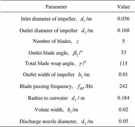
Table 1 Main parameters of the test pump
A CAD model is generated first as shown in Fig.1. The computing model includes (1) the pump ca- vity, (2) the impeller, (3) the volute and (4) the discha- rge pipe. As the impeller (2) has a relative rotation with respect to the three other parts, six surfaces are created as the interfaces between (1)-(2), (1)-(3) and (3)-(4). Figure 1 shows the details of the computing model and the interfaces. In Fig.1, the surface A ser- ves as the interface between the volute and the discha- rge pipe. The surface B is the interface between the pump cavity and the volute. The surface C, D, E and F are used as the interfaces between the pump cavity and the impeller.
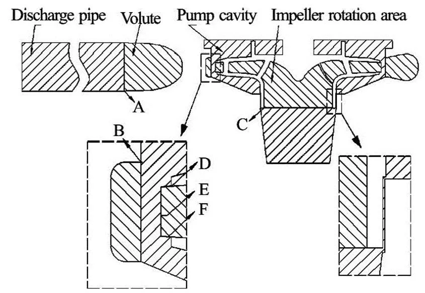
Fig.1 Sketch of the computing model for the test pump
The commercial software CFX is used to solve the transient 3-D Navier-Stokes equations in the whole pump. In order to simulate the rotational effect, the multiple frames of reference are involved. The im- peller is set in the rotational frame of reference. The pump cavity, the volute and the discharge pipe are set in the stationary frame of reference. The interfaces A and B are set as the general grid interface (GGI). The interfaces C, D, E and F are set as the Rotor/stator in- terface in the transient analysis, and the frozen rotor interface in the steady state analysis.
The turbulence is modeled by the LES method, based on the idea of resolving the large flow scales and modeling the smaller ones. Before the CFD calcu- lation, the computing grid is checked to decide whe- ther it is suitable for the LES model by comparing the mesh size with the four eddy scales. The four eddy scales are defined as[16]:
Large eddy scale
Taylor scale
Kolmogorov scale
Mesh scale
To perform the mesh size check, three grid topo- logies, namely Grid A, Grid B and Grid C, are genera- ted by using the code Gridpro 5.1. Figure 2 presents the mesh of the test pump. In order to make use of the LES model, the node of the first cell-layer away from the impeller surface is specified to be 10-6m, which makes the localof the impeller surface less than 1.0, as shown in Fig.3. The dimensionless distance meets the requirements of the LES model. Additiona- lly, the mesh size is determined by comparing the mesh scale with the scales,as well as. The details of varying grid sizes are shown in Table 2. Figure 4 (is the angle) presents the comparisons among the four scales.
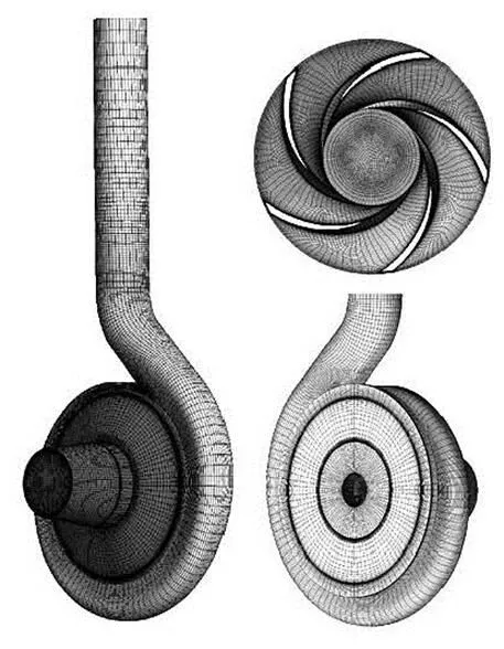
Fig.2 Mesh of the computing model
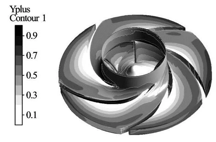
Fig.3 distributions on the impeller surfaces
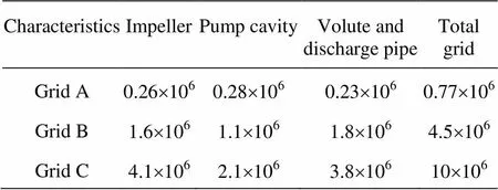
Table 2 Details of varying pump grid sizes
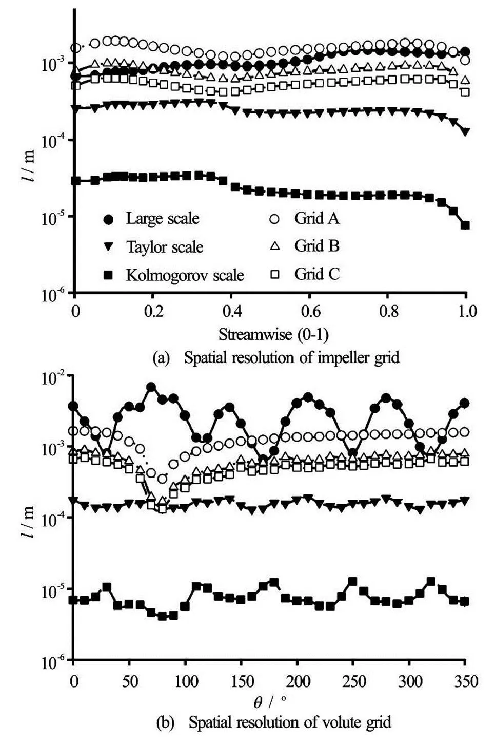
Fig.4 Spatial resolution of grid
The area-averaged values of the scales,andon the meridional surface of the impeller are calcu- lated by the steady CFD computation, as shown in Fig.4(a). The streamwise 0 and 1 represent the impe- ller inlet and outlet, respectively. Also, the area ave- rage values on the circumferential surface in the volu- te are obtained, as shown in Fig.4(b). The anglere- presents the circumferential position of the volute. In Fig.4, it can be observed that the mesh scales of Grids B and C fall between the large eddy scaleand the Taylor scale. The mesh size of Grid B is close to the Taylor scale and has the same order of magnitude. Apparently, the mesh size can guarantee that the filter length is less than the Taylor scale by increasing the number of grids. However, this will lead to a higher requirement for computer performance. At present, the simulations in this study are carried out on a clu- ster of twelve Intel Xeon 5600 nodes. According to this figure, the Grid C is considered to be reliable to ensure the mesh check for the LES model.
2. Acoustic simulation method
The tensor equation of the generalized Lighthill acoustic analogy can be written in the form[17,18]
Equation (1) is the basic equation of Lighthill. On the right hand side of the equation, there are three terms named the quadrupole source, the dipole source and the monopole source. The dipole source is the most important in centrifugal pumps[1].
In the study, a commercial code Sysnoise is em- ployed to interpolate the pressure fluctuation on the four surfaces onto corresponding surfaces of the acou- stical models. The Fast Fourier Transform with a Hanning window is used to analyze the pressure flu- ctuation and transform them to the surface dipole sou- rces. The direct boundary element method (DBEM) is applied to calculate the sound pressure radiated by the four different surface dipole sources. In the calcula- tion, the dipole sources are treated as the acoustical boundary, and the inlet and outlet of the acoustical model are set to be an absorption boundary. In order to study the influence of the four surface dipole sou- rces on the acoustic calculating accuracy quantitative- ly, the four dipole sources are analyzed with their combinations. The combinations are shown in Table 3.
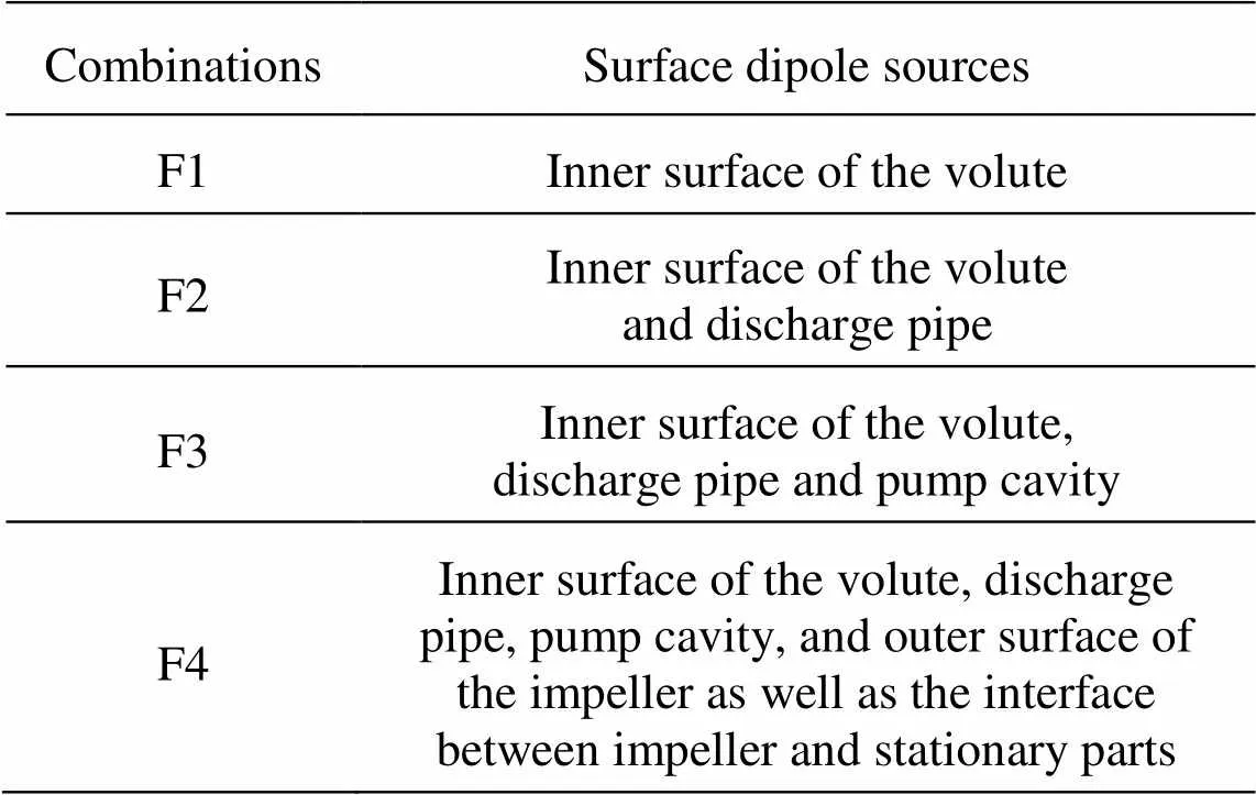
Table 3 Combinations of the four dipole sources
3. Experiment setup
The experiments are carried out in a close hy- draulic rig, as shown in Fig.5. The pump in the rig is driven at a constant speed of 2 900 r/min by a variator, with a blade passing frequency of. The torque is measured through a Hall-effect sensor. In the rig, the flow rate is controlled by a flow valve installed downstream on the outlet pipe, and the flow rate is measured by a turbine flow meter. The mean static pressure is tested through two piezoresistive pre- ssure sensors installed at the inlet and the outlet of the pump. The measuring ranges of the sensors are-100 kPa-100 kPa and 0 kPa-600 kPa, respectively. A ST70 type hydrophone is used to measure the sound pressure in the pump. The hydrophone is installed in the discharging pipe at least 5 pipe diameters down- stream of the pump outlet. Four PCB 352A60 accele- rometers with the sensitivity of 10 mv/(m/s2) are used to measure the vibration of the pump. These accelero- meters are fixed on the inlet flange, the outlet flange, the volute and the foundation, as shown in Fig.1. Si- gnals from the pressure sensors, the hydrophone and the accelerometers are translated to electric signals, which are collected by a PXI-4472B data acquisition module and converted to digital signals. The data are finally analyzed by using the code LabVIEW in a computer. Figure 6 shows the signal transference in this study.
Fig.5 Sketch of the experiment setup
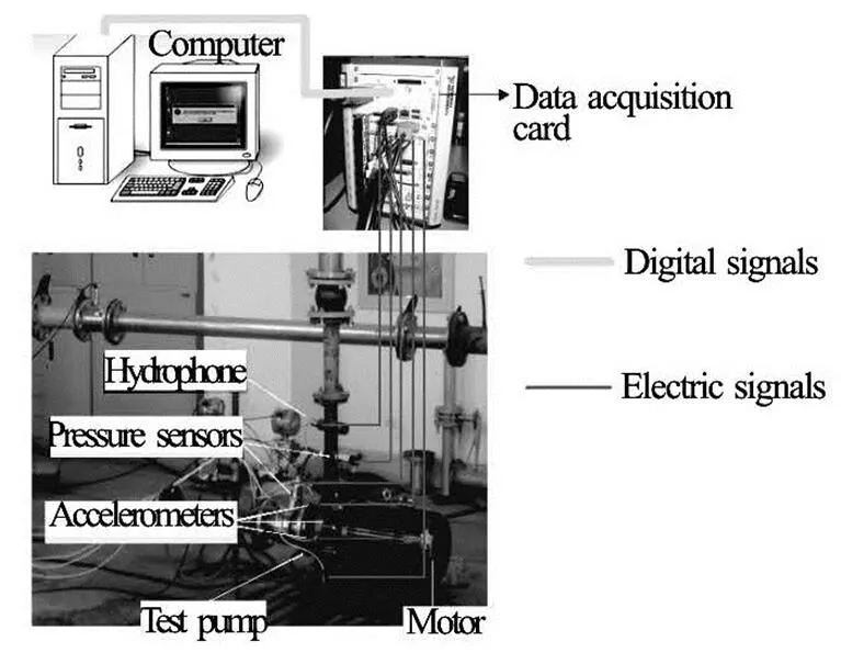
Fig.6 Signal transference
The ST70 type hydrophone has a frequency range of 50 Hz to 70 000 Hz, and the sensitivity of the received acoustic pressure is-204 dB rev.1 1 V/μPa. The hydrophone is located at a distance four times of the diameter of the discharge pipe downstream the pump outlet. The hydrophone is flush-mounted into the discharge pipe, which is conducive to the measure- ment of the flow-induced noise with little influence on the flow field in the pump.
According to the Nyquist-Shannon sampling theorem, the actual signal sampling frequency should satisfy the condition of. In this study, the rotor frequency is(2 900 r/min). The in- terested frequency range is 12 times greater than the rotor frequency. From the Nyquist-Shannon sampling theorem, the signal sampling frequency is set as1 200 Hz, and the sampling number is chosen as2 400. The analysis frequency is 600 Hz.
4. Results and analyses
4.1
Before the acoustic calculation method is applied to the practical engineering problem, the present LES simulation is validated through the unsteady experi- mental results. The pressure fluctuation at the pump outlet is used to validate the CFD predictions. Figure 7 presents the numerical and experimental pressure pulsations during an impeller revolution at the design flow rate. Although the numerical pressure is not al- ways the same as the experimental data at the same time, it can be observed from Fig.7 that the compari- son between the numerical results and experimental data sees a quite good agreement.
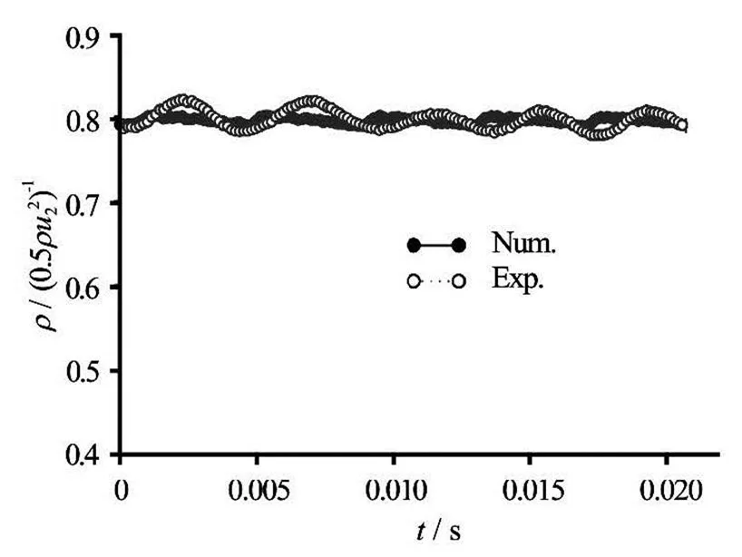
Fig.7 Pressure fluctuations at the pump outlet obtained experi- mentally and numerically
Once the numerical results are validated, the nu- merical model is used to investigate the internal tran- sient flow fields in the pump. The transient velocity fields in the pump during one single blade passage pe- riodare presented in Fig.8. Two turbulence mo- dels are used to calculate the turbulence effect in the pump, the LES model and the RANS model (standardmodel). The results obtained by the two models are compared as shown in Fig.9. And the results indi- cate that the predictions from the LES model show more details of the flow structures than those from the RANS model.
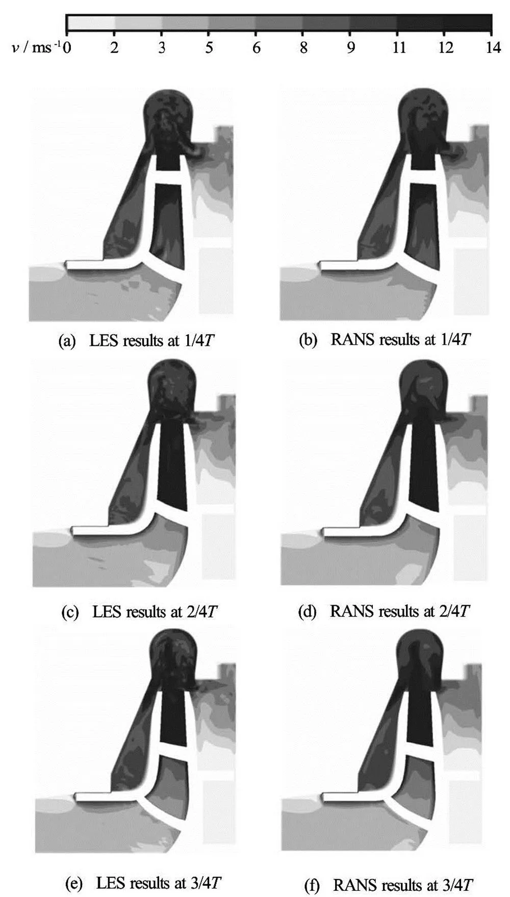
Fig.8 Internal transient flow fields in the pump
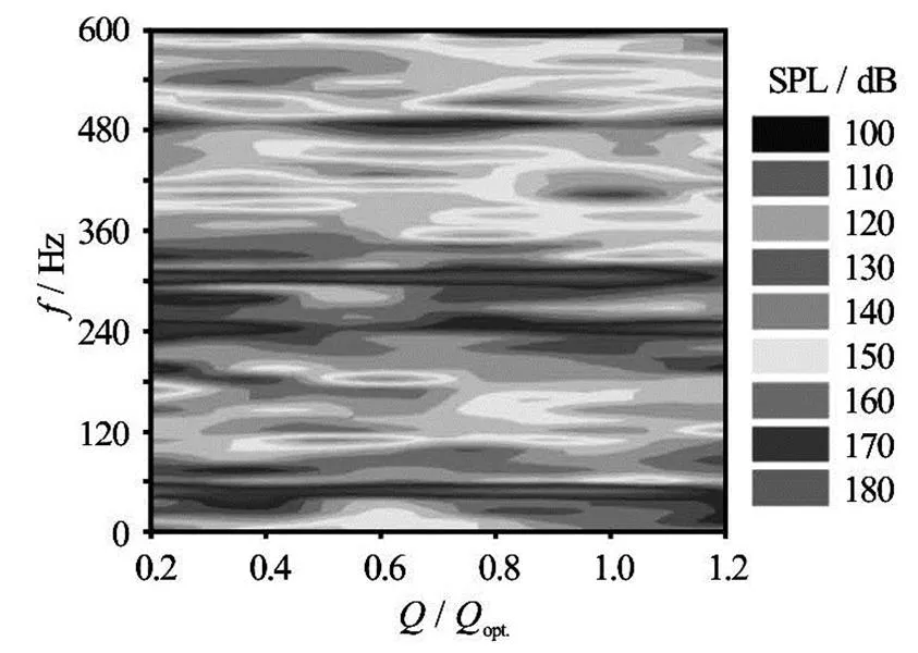
Fig.9 Measured hydraulic noise spectra at several flow rates
Obviously, the velocity takes a high value in the pump cavity, especially in the front cavity. That is be- cause the flow in the cavity is strongly coupled with the main flow at the impeller outlet by exchange of momentum through the leakage, which can accelerate the fluid rotation in the cavity. However, the leakage is zero in the rear cavity while the leakage is always present in the front cavity. This indicates that the front cavity cannot be ignored in view of the high momen- tum there.
Additionally, it can be observed that the velocity of the fluid flowing along the front casing wall varies with time. This is because the inlet boundary condi- tion for the flow through the front cavity is determined by the velocity distribution at the impeller outlet. The time varying velocity distribution can lead to an alter- nating momentum in the cavity, which may cause a certain level of vibration and noise.
4.2
Before discussing the acoustic simulation accura- cy, the hydraulic noise and the vibration obtained ex- perimentally are compared. Figure 9 shows the mea- sured noise spectra at several flow rates (SPL is short for sound pressure level). Figure 10 (is the amplitu- de of vibration, while therepresents the position of monitor area) presents the vibration at the four moni- toring points at the design flow rate. In these figures, the frequencyrepresents the shaft fre- quency, andrepresents the blade pa- ssing frequency. The sound pressure level is obtained by the equation
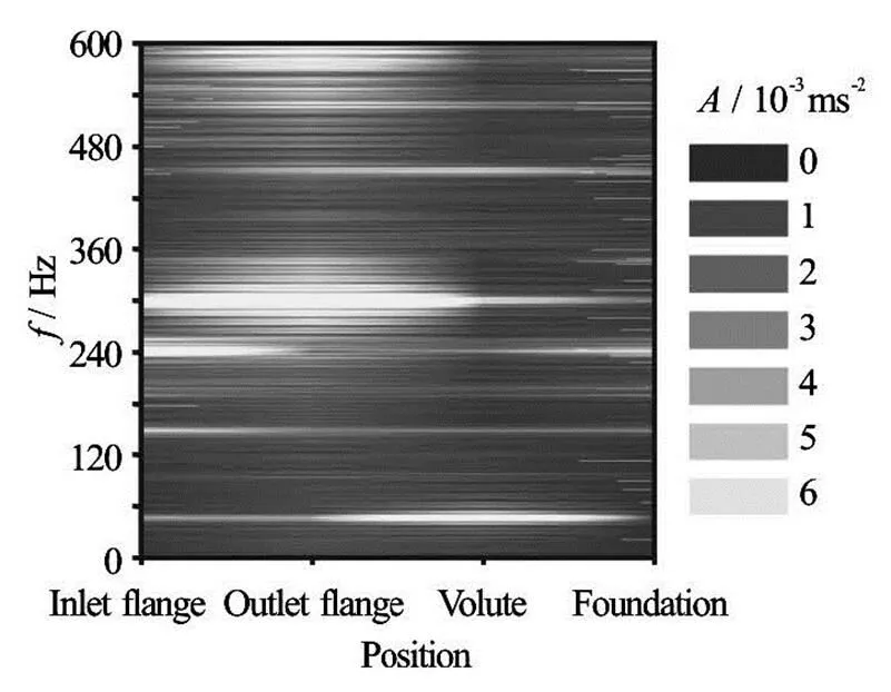
Fig.10 Measured vibration spectra at four positions under desi- gn flow condition
It can be seen from Fig.9, there are five main peaks of the hydraulic noise, at 48.3 Hz, 241.7 Hz, 300 Hz, 483.4 Hz and 600 Hz. And the values at 300 Hz and 600 Hz are higher than those at other fre- quencies. Similar features can be found in Fig.10. It can be seen that the peaks at 48.3 Hz, 241.7 Hz and 483.4 Hz are related to the shaft frequency and the blade passing frequency. However the high peaks at 300 Hz and 600 Hz have nothing to do with the chara- cteristic frequency of the rotor. This can be explained by Fig.10. From this figure, it can be seen that the high peaks at the two frequencies are mainly located on the inlet and outlet flanges. For the volute and the foundation, the vibration level at the two frequencies is not as high as that on the inlet and outlet flanges. This indicates that the strong vibration at the two fre- quencies might be caused by the pipe resonance. By comparing the measured hydraulic noise with the vib- ration in Fig.9 and Fig.10, it is found that the peaks at the 300 Hz and 600 Hz are related to the pipe’s reso- nant frequencies.
After the analysis of the characteristic frequency of the hydraulic noise, the sound pressure radiated from the four combinations of the surface dipole sou- rces is calculated and compared with the experimental results. The sound pressure level obtained numerically and experimentally at three flow rates is shown in Fig.11, Fig.12 and Fig.13, respectively.
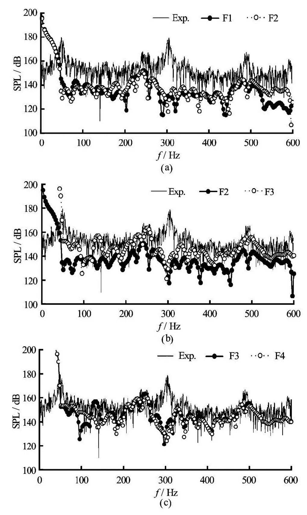
Fig.11 Sound pressure levels under condition
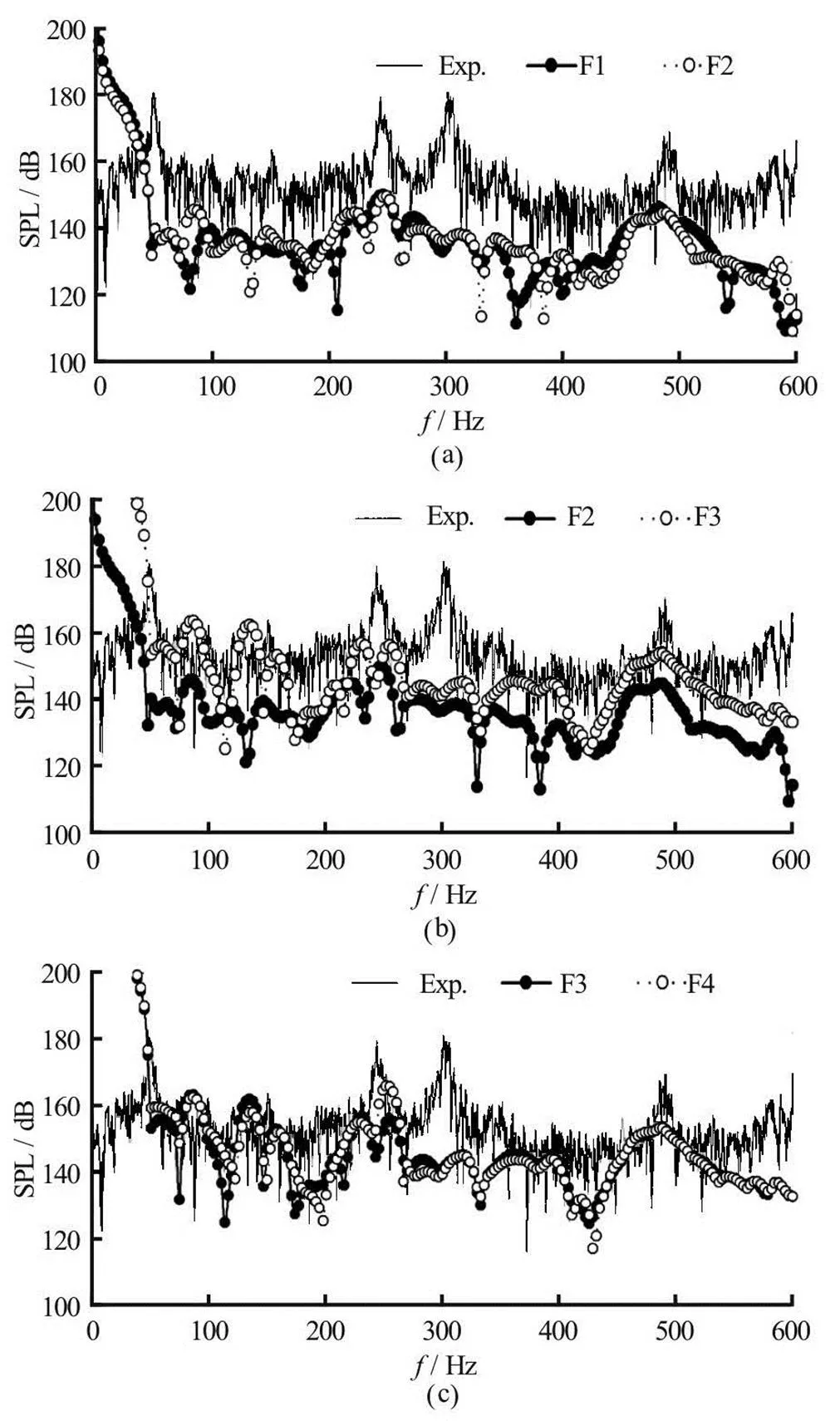
Fig.12 Sound pressure levels under condition
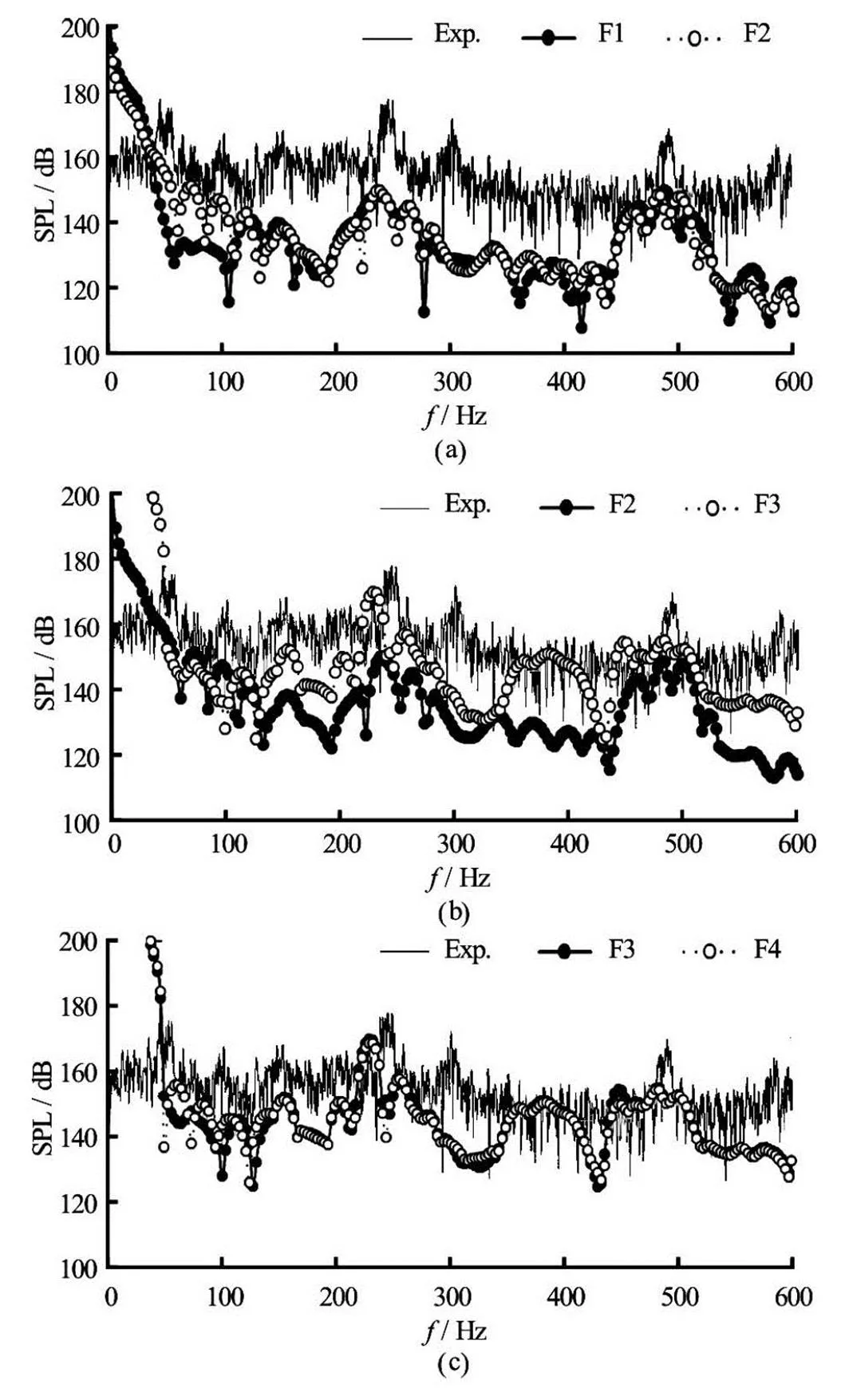
Fig.13 Sound pressure levels under condition
It can be seen from these three figures that the sound pressure curves of the combination F3 and F4 are in a good agreement with the experimental data. Especially at some special frequencies, including the shaft frequencyand at the blade pa- ssing frequencyas well as the twice of the blade passing frequency, the difference between the numerical results and experi- mental data is relatively small. However, at the fre- quencies of 300 Hz and 600 Hz, the relative error is very large. That is because the effect of the pipe reso- nance has not been considered in the present CFD and acoustic calculating methods. But from a qualitative perspective, the CFD combined with the Lighthill acoustic analogy methods applied in this study are feasible for the acoustic simulation.
The effect of the dipole source of the discharge pipe is investigated through comparing the combina- tion F1 and F2. As shown in Fig.11, Fig.12 and Fig.13, the two sound pressure curves of F1 and F2almost overlap. Obvious differences between the numerical results and the experimental data are clearly visible according to these three figures. The relative differe- nce between the predicted values and the experimental results is over 12%, and it increases with the growing flow rate. The results suggest that the pressure fluctua- tions on the discharge pipe surface have little effect on the acoustic calculating accuracy.
The effect of the dipole source of the pump cavi- ty is studied by comparing the combination F2 and F3. According to Fig.11, Fig.12 and Fig.13, the sound pre- ssure curves of F3 are obviously closer to the experi- mental data. And the curvilinear trend of F3 curves agrees well with the experimental curve. Especially at the blade passing frequencyand the twice of the blade passing frequency, the relative differe- nce between the predicted values of F3 and the experi- mental results are within 5%. However, in the vicinity of the frequencies of 300 Hz and 600 Hz, the relative error is large. It is consistent with the results discussed in the previous section. But from a qualitative perspe- ctive, the numerical error can be reduced by about 7% through considering the effect of the pump cavity in the acoustic model, comparing with the acoustic pre- dictions of F2. This indicates that the acoustic accura- cy can be improved by including the dipole source of the pump cavity in the simulation.
The sound pressure curves of F3 and F4 are com- pared in Fig.11, Fig.12 and Fig.13 in order to see the effect of the rotation of the impeller. As can be seen from these figures, the two sets of curves are consiste- nt with each other. It is found that the pressure flu- ctuations on the outer surface of the impeller as well as on the interface between the rotor and the stator have little effect on the acoustic results. The results in- dicate that the main acoustic source is not the impeller surface but the casing surface, as expected in the stu- dies conducted by Kato et al.[19]and He et al.[20].
The sound pressure distributions at the frequency ofare calculated at three flow rates. During the computation, the dipole sources including the volute surface and the pump cavity are treated as the bounda- ry condition. The directivity distribution of the sound pressure level atis shown in Fig.14. It is found that there are five peaks of the sound pressure in the pump, corresponding to five blades of the impeller. That is due to the influence of the rotor-stator intera- ction of centrifugal pumps. The sound pressure level reaches its maximum value at the volute tongue zone. Comparing the results between the three flow condi- tions, the sound pressure level increases with the gro- wing flow rates, with the largest magnitude at the ton- gue zone.
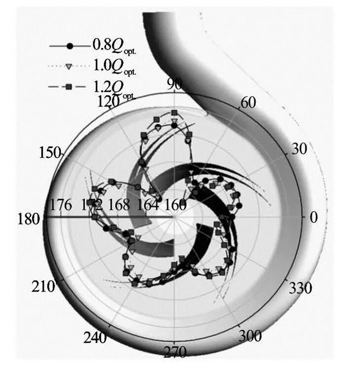
Fig.14 Directivity distribution of the sound pressure levels at the blade-passing frequency for three flow rates
5. Conclusions
On the basis of the LES turbulence model combi- ned with the Lighthill acoustic analogy methods, the influences of the four different surface dipole sources in a centrifugal pump on the acoustic calculating accu- racy are studied. The four surface dipole sources are analyzed by their combinations. By comparing the nu- merical results of the four combinations with the ex- perimental data, conclusions are drawn as follows:
(1) The pressure fluctuations on the discharge pipe surface and the outer surface of the impeller have little effect on the acoustic simulation results.
(2) The pressure pulsations on the inner surface of the pump cavity play an important role in the inte- rnal flow and the acoustic simulation. The acoustic calculating error can be reduced by about 7% through considering the effect of the pump cavity.
(3) There are five peaks of the sound pressure in the pump, corresponding to the number of the blades. And the sound pressure level increases with the gro- wing flow rates, with the largest magnitude at the ton- gue zone.
References
[1] LANGTHJEM M. A., OLHOFF N. A numerical study of flow-induced noise in a two-dimensional centrifugal pump: Part I Hydrodynamics[J]. Journal of Fluids and Structu- res, 2004, 19(3): 349-368.
[2] NORTON M. P., KARCZUB D. G. Fundamentals of noise and vibration analysis for engineers[J]. Noise Control En- gineering Journal, 2007, 55(2): 275-276.
[3] CHOI J. S., MCLAUGHLIN D. K. and THOMPSON D. E. Experiments on the unsteady flow field and noise genera- tion in a centrifugal pump impeller[J]. Journal of Sound and Vibration, 2003, 263(263): 493-514.
[4] TIMOUCHEV S., TOURRET J. Numerical simulation of BPF pressure pulsation field in centrifugal pump[C]. 19th International Pump Users Symposium. Lausanne, Switzerland, 2002, 85-105.
[5] SRIVASTAV O. P., PANDU K. R. and GUPTA K. Effect of radial gap between impeller and diffuser on vibration and noise in a centrifugal pump[J]. Emerging Trends in Mechatronics for Automation, 2003, 32(13): 36-39.
[6] YUAN Shou-qi, SI Qiao-rui and XUE Fei et al. Numerical calculation of internal flow-induced noise in centrifugal pump volute[J]. Journal of Drainage and Irrigation Ma- chinery Engineering, 2011, 29(2): 93-98(in Chinese).
[7] LIU Hou-lin, DING Jian and TAN Ming-gao et al. Analy- sis and experimental of centrifugal pump noise based on outlet width of impeller[J]. Transactions of the Chinese Society of Agricultural Engineering, 2013, 29(16): 66- 73(in Chinese).
[8] TAN Ming-gao, WANG Yong and LIU Hou-lin et al. Ef- fects of number of blades on flow induced vibration and noise of centrifugal pumps[J]. Journal of Drainage and Irrigation Machinery Engineering, 2012, 30(2): 131- 135(in Chinese).
[9] WANG M., FREUND J. B. and LELE S. K. Computatio- nal prediction of flow-generated sound[J]. Annual Re- view of Fluid Mechanics, 2005, 38(1): 483-512.
[10] KATO C., YAMADE Y. and WANG H. et al. Numerical prediction of sound generated from flows with a low Mach number[J]. Computers and Fluids, 2007, 36(1): 53-68.
[11] PEI Ji, YUAN Shou-qi and LI Xiao-jun et al. Numerical prediction of 3-D periodic flow unsteadiness in a centrifu- gal pump under part-load condition[J]. Journal of Hydro- dynamics, 2014, 26(2): 257-263.
[12] WANG Zhen-yu, YANG Ai-ling and DAI Ren. Numerical prediction of the flow-induced noise of centrifugal pump[J]. Journal of Mechanical Engineering, 2012, 48(6): 162-167(in Chinese).
[13] JIANG Y. Y., YOSHIMURA S. and IMAI R. et al. Qua- ntitative evaluation of flow-induced structural vibration and noise in turbomachinery by full-scale weakly coupled simulation[J]. Journal of Fluids and Structures, 2007, 23(3): 531-544.
[14] WAGNER C. HUTTL T. and SAGAUT P. Large-eddy simulation for acoustics[M]. New York, USA: Cambridge University Press, 2007.
[15] HSU Y., BRENNEN C. E. Effect of swirl on rotordyna- mic forces caused by front shroud pump leakage[J]. Jour- nal of Fluids Engineering, 2002, 124(4): 1005-1010.
[16] GULEREN K. M., TURAN A. and PINARBASI A. Large-eddy simulation of the flow in a low-speed centrifu- gal compressor[J]. International Journal for Numerical Methods in Fluids, 2008, 56(8): 1271-1280.
[17] COLONIUS T., LELE S. K. Computational aeroacoustics: Progress on nonlinear problems of sound generation[J]. Progress in Aerospace Sciences, 2004, 40(6): 345-416.
[18] JEON W. H., LEE D. J. A numerical study on the flow and sound fields of centrifugal impeller located near a wedge[J]. Journal of Sound and Vibration, 2003, 266(4): 785-804.
[19] KATO C., KAIHO M. and MANABE A. An overset fini- te-element large-eddy simulation method with applications to turbomachinery and aeroacoustics[J]. Journal of App- lied Mechanics, 2003, 70(1): 32-43.
[20] HE Tao, ZHONG Rong and SUN Yu-dong. Numerical method on hydrodynamic noise of centrifugal pump[J]. Journal of Ship Mechanics, 2012, 16(4): 449-455(in Chinese).
* Project supported by the National Natural Science Foun- dation of China (Grant Nos. 51309120, 51509109), the Natio- nal Key Technology Support Program of China (Grant No. 2013BAF01B02) and the Jiangsu Province Science and Technology Support Program of China (Grant Nos. BA2013127, BE2014879 and BA2015169).
Biography: Hou-lin LIU (1971-), Male, Ph. D., Professor
Corresponding author: Ming-gao TAN, E-mail: tmgwxf@ujs.edu.cn
10.1016/S1001-6058(16)60606-6 2016,28(1):43-51
猜你喜歡
教育家(2022年18期)2022-05-13 15:42:15
求學(xué)·理科版(2020年4期)2020-05-13 14:03:12
小天使·一年級(jí)語(yǔ)數(shù)英綜合(2019年8期)2019-08-27 02:23:00
求學(xué)·理科版(2019年3期)2019-03-30 03:23:12
金橋(2018年12期)2019-01-29 02:47:44
Acta Mathematica Scientia(English Series)(2018年5期)2018-11-22 09:23:58
河南電力(2017年4期)2017-11-30 06:09:43
中學(xué)生理科應(yīng)試(2017年4期)2017-07-08 20:03:22
高中生學(xué)習(xí)·高三版(2017年6期)2017-06-12 14:04:02
中學(xué)生數(shù)理化·八年級(jí)數(shù)學(xué)人教版(2016年5期)2016-08-23 10:08:32
 水動(dòng)力學(xué)研究與進(jìn)展 B輯2016年1期
- 水動(dòng)力學(xué)研究與進(jìn)展 B輯的其它文章
- Ski-jump trajectory based on take-off velocity*
- Formation of air-entraining vortices at horizontal intakes without approach flow induced circulation*
- Numerical simulation of flow and bed morphology in the case of dam break floods with vegetation effect*
- Numerical study of the flow in the Yellow River with non-monotonous banks*
- Pelton turbine: Identifying the optimum number of buckets using CFD*
- Mass transport in a thin layer of power-law fluid in an Eulerian coordinate system*