Effect of Air Injector on the Performance of an Air-lift for Conveying River Sand
TANG Chuanlin, HU Dong, PEI Jianghong, and YANG Lin
1 College of Mechanical Engineering, Hunan University of Technology, Zhuzhou 412008, China
2 Department of Mechanical Engineering, Chongqing Jiaotong University, Chongqing 400044, China
1 Introduction
At present, the various high quality mineral source and available exploitation of mineral deposit are reducing day by day, thus, seeking new mineral sources has become a pressing issue. However, the presence of complicated hydrogeology condition in certain mining area leads to perennial overstock of exploration achievements, and thereupon the rich underground resources become “dead mineral”, such as ferromanganese ore, copper mine, gold deposits, zinc minerals and beach placer distributed in Hunan, Yunnan, Jiangxi, Sichuan and Guangdong Provinces of China. These mineral deposits are buried underground from several meters to hundred of meters in the form of botryoidalis, sand-shaped and powder body,there existed perennial underground river is near the mineral body with complex block structure, most of which have high water cut and water conductivity. Both ore body roof and footwall, which belong to the karst formation,move with favorable development, so the existing fissure-cavern water is extremely rich and result in large pit inflow of water. Therefore, the traditional mining methods are unable to realize for this kind of ore bed, and the air-lift has been developed, which can also increase the mining efficiency, decrease operational cost, improve working environment, and lessen working intensity[1–3].
During the previous studies, the air-lift was also analyzed in terms of the theory of two-phase flow. Many studies were carried out through theoretical analysis,numerical simulation and experimental observation.Experimental studies so far made in this field are those of KATO, et al[4], APAZIDIS[5], YOSHINAGA, et al[6],LIANG[7], AKIRA[8], FUJIMOTO, et al[9–10]. They proposed models which described the flows in the upriser and performed much experimental investigation on the performance of air-lift device, the research findings of their investigation are as follows.
(1) The frictional loss model has been proposed based on the theory of three-phase flow, the model which describes the efficiency of an air-lift has been also established. The effect of the air-lift variables (air flow rate, submergence ratio, design of footpiece) on its performance was investigated, and the results showed that the key influencing factors of performance were the air flow rate and air injector.
(2) The flow patterns distribution, velocity profiles of each phase and air bubbles movement feature were proposed based on the gas-liquid two-phase flow, the effect of the bubble size and bubble injector configuration on an air-lift efficiency were also analyzed. In addition, the critical air flow rate and the particle motion in the upriser were investigated in detail by means of theory analysis and experimental observation, respectively.
The study on the air-lift is still at the starting stage at present in China, the method using air-lift and self-excited oscillation jet for exploiting deep beach placer in Hainan Province of China (1999) and ferromanganese ore in Hunan Province of China (2005) was presented by the author. It has been shown theoretically and experimentally that the self-excited oscillation pulsed jet not only crushes and looses ore deposit underwater, but also lifts solid particles on the clay and sand bed, the jet from nozzle makes solid particles enter the end of the suction pipe more easily. An improvement in the efficiency of as much as 20% is reached with the use of appurtenances device mentioned above[11].
In the current study, the effect of parameters (air flow rate, air injection pipes, number of nozzles, particle size and submergence ratio, etc) on the air-lift performance is investigated theoretically and experimentally, and most investigators carried out experiments with small upriser(the internal diameter of the upriser ranges from 20 mm to 60 mm). However, few experiments have been performed on the air injection method, especially the injection angle.The main objective of the present work is to study the effect of air injection method on the air-lift performance with the use of large lifting pipe from practical engineering application based on experiments for mining simulation.
In this research, the experimental apparatus of an air-lift system is constructed and made available for evaluating the performance of air-lift device. In section 2, the principle of the air-lift is analyzed and the calculation of lifting efficiency is built. Then in section 3, the experimental process and its related equipments are introduced.Subsequently, the performance of an air-lift is investigated in the case of number of nozzles, air injection angle and arrangement of air injection pipes, respectively. At last,discussions and conclusions are given in section 4.
2 Principle of the Air-lift and Calculation of Lifting Efficiency
The air-lift consists of an air compressor, an air injector,and a vertical lifting pipe that is open at both ends (Fig. 1).Compressed air is injected into the lifting pipe through the air injector, with buoyancy driving the air bubbles upward within the liquid. The bubbles soon coalesce to an extent that their cross-sectional diameter is almost the same as the pipe diameter, and then the large bubbles are broken into small bubbles. As a consequence, the liquid and the large air bubbles appear alternately along the pipe. Such bubble motion leads to upward liquid flow, and so liquid is transported along the lifting pipe. From this standpoint, the bubbles motion is the original power of lifting liquids and particles. In this case, the driving mechanism for conveying solid particles is the frictional drag force exerted by the surrounding liquid or air-liquid mixture. When the upward drag force on the particles is larger than the gravitational force, the solid particles can be lifted.
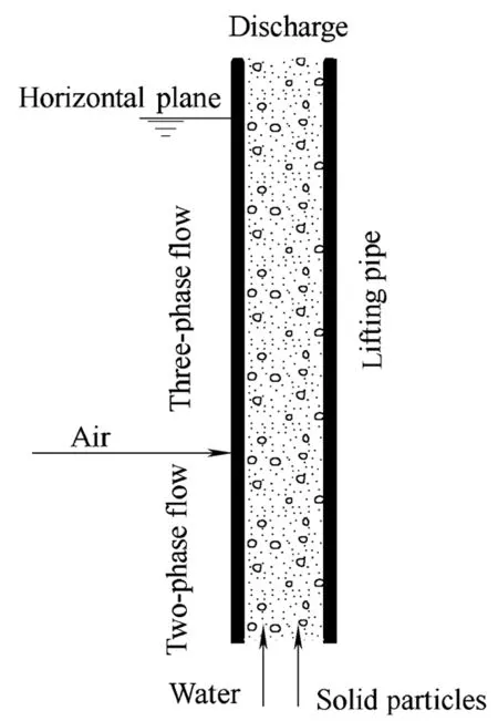
Fig. 1. Schematic diagram of air-lift
In order to obtain dimensionless parameters for the air-lift without considering the pressure loss in the lifting pipe behind the injection orifice, and thus, to compare the performances of the air-lift when different designs of the air injection are utilized, a suitable parameter for comparison is the mass of the pumped water and solid particles per unit mass of air supplied, here called the lifting efficiency,which is given as[12]

Where ηLSis the total efficiency of containing water and solid particles; qgthe air flow rate, m3/h; qLthe discharged water flux, L/min; qmgthe air mass flow, kg/s; qmSthe mass flow of solid particles, g/s; ρLthe liquid density and ρgthe density of the jet flow, kg/m3.
3 Experimental Investigations on the Performance of an Air-lift
3.1 Experimental apparatus and procedure
The experimental apparatus shown in Fig. 2 is set up and made available for evaluating the air-lift performance. The body of the air-lift consists of a lifting pipe, a water reservoir, an air injector, a particle feeder, and an air separator. The amount of water in the water reservoir is controlled by regulating the water flow controller. The air-lift is steadily operated by supplying air and particles at each fixed flow rate and by keeping the water level maintained at a preset height. To measure the respective water flux and the mass flow of solid particles, the water is led to a metering tank while the particles are led to the sand reservoir for measurement. The respective flow of the water and the particles are measured 5 times to determine the average for every run.
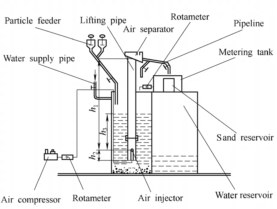
Fig. 2. Schematic diagram of experimental setup
The total height, h1+h2, of the lifting pipe is 3 m and the pipe diameter D is 80 mm. h1(distance between air separator and nozzle) and h3(which is measured from the bottom of lifting pipe to nozzle) are variable due to exchanging the length of air injection pipes. The nozzle is set at h2above the bottom of the lifting pipe and its injection angle can be adjusted within 45°. The river sand of 3 mm in diameter is used as the solid particles. The material density, ρs, of sand is 2 540 kg/m3. The mean flow rate of the supplied solid particles is kept nearly constant, which is 200 g/s measured by ten times in this experiment. The submergence ratio,which is defined as γ=h3/h1, is controlled by regulating the water level and the air injection method.
The air flow rate is regulated by the flow valve of an air separator and measured by an air flow controller, the type of which is LZB-50. In the present experiment, the air flow rate reduced to the atmospheric pressure is in the range of 0<qg≤100 m3/h, the measurement accuracy of qgis within±1.5%; LZB-100F is chosen in order to measure the water flux, which changes from 8 m3/h to 40 m3/h with a range of error within ±2.5%. The mass flow rate of solid particles can be defined as the mass of the pumped particles per unit time with ±1.5%. The uncertainty in the concentration of particles, which is defined as Cs=qmS/60qL, and lifting efficiency can be computed as ±3% and ±4%, respectively.
The objective of this research is to investigate the effect of air injection method on the air-lift performance by changing N, α, qgand the arrangement of air injection pipe,the N and α denote the number of nozzles and the injection angle, respectively. In this study, qmS, qL, Csand ηLScan be tested and calculated for evaluating the operation performance of air-lift.
The air injector (Fig. 3) consists of air distributing plate,air injection pipes and nozzles. It controls the shape and volume of air bubbles. The air distributing plate is a disk in which holes with different sizes and numbers are drilled,three discs are used with different hole sizes, which mach with nozzles, and numbers to provide a fixed cross-sectional area, nominally 2 827 mm2, to cover the intended experimental range. In this research, the number of holes in the air distributing plate is 1, 3 and 4,respectively, as shown in Fig. 4, the size specifications of which can be obtained according to the inner diameter of air injection pipes, which is larger than that of nozzles. The air injection pipes, one end of which are connected to the nozzle and the other are clamped to the disk, can be replaced. For the sake of convenience, the classification of air injection method is shown in Table.
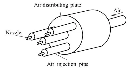
Fig. 3. Schematic diagram of air injector
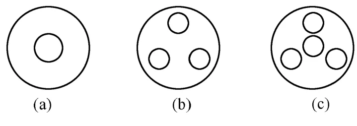
Fig. 4. Schematic diagram of the style of air distributing plate
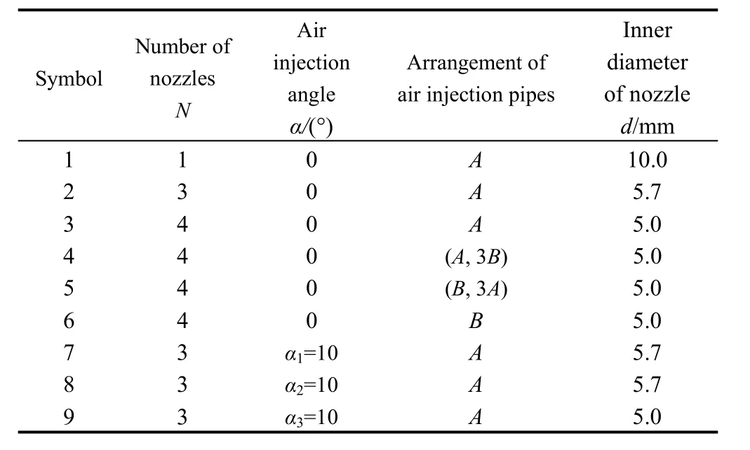
Table. Specifications of air injection method
In Table, A and B denote that the length of air injection pipe are 40 mm and 70 mm, respectively. (A, 3B) indicates that the pipe A is connected to the center hole while the pipe B are mounted to the other three holes on the distributing plate, and (B, 3A) shows the reverse arrangement of the air injector mentioned above. Fig. 5 shows the air injection angle α, α=0° depicts the nozzle is parallel to the axial of lifting pipe, α1and α2denote the angles of nozzle deflect inward and external along the axial of lifting pipe, respectively, which represents the main flow direction here; and α3is the angle of nozzle deflecting toward the tangential direction of pipe wall. The air injection pipe is installed at the center hole with using symbol 1. When investigating other arrangement of air injector, the distributing plate should be changed another disk with three or four holes.
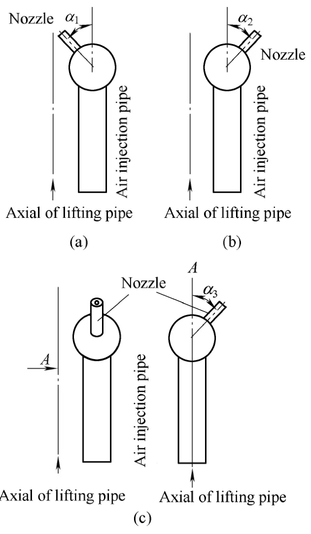
Fig. 5. Schematic diagram of air injection angle
3.2 Results and discussion
3.2.1 Performance curves of an air-lift in the case of number of nozzles
For comparison, the experiment is carried out in the case of symbols 1, 2 and 3, respectively, namely, the variations of the water flux, mass flow of solid particles,concentration of particles and lifting efficiency with air flow rate are investigated in this study at a given value of γ=h3/h1=0.65. Fig. 6 depicts typical performance curves of the air-lift which describe the relation mentioned above.
Fig. 6(a) demonstrates the water flux increases with the air flow rate gradually, firstly reaches a peak, and then slightly decreases in all cases. This may be due to the change of flow patterns from bubbly flow to agitated flow because of increasing air flow rate, so the lift capacity increases greatly, but when continue increasing the air flow rate, the flow patterns turn into annular flow, and thus the momentum loss increases due to wall friction. The air injector with three nozzles shows the highest discharged water flux at any given air flow rate, and that with one nozzle gives the lowest water flux, the former is larger by about 36% than the latter at low air flow rate, the value is still 10% in the case of high air flow rate. It is also found that the water flux with three nozzles is slightly larger than that with four nozzles. This can be attributed to the distribution of flow patterns, the better of which in the lifting pipe with three nozzles can be formed and redound to lift liquid and solid particles.

Fig. 6. Performance curves of an air-lift for different number of nozzles
Fig. 6(b) represents the mass flow of solid particles versus the supplied air mass flow rate for the same submergence ratio mentioned above, the performance curves show similar trends to Fig. 6(a), this can be explained that the capability of lifting is due to the flow in the lifting pipe, the particle motion can be regarded as the same trend as characteristic of the water flow in the case of fine particle. The relation between concentration of particles and air flow rate is shown in Fig. 6(c), the concentration of particles at the outlet of lifting pipe with three nozzles gives the maximum value during the three arrangements of injection pipes, but the concentration is the lowest in the case of one nozzle. It is found that the performance curves described by concentration of particles and air flow rate are shown by the sawtooth function because of the particle feeder supplying insufficient solid particles.
From the observation in Fig. 6(d), the performance curves show the similar trends to that in Figs. 6(a) and 6(b).The highest lifting efficiency of the air-lift, which is 43.21% at qg=38 m3/h, also belongs to the symbol 2 with three nozzles, the efficiency for the case of one nozzle is the lowest. Owing to the variation of the flow pattern, it improves the capability of lifting liquid-solid mixture,meanwhile, the appropriate flow pattern results in less friction losses and small value of the air void fraction in the lifting pipe, and thus, the lifting efficiency increases. In addition, it is seen from the experiment that the critical value of air flow rate for lifting particles with using three or four nozzles is much less than that with one nozzle used.
3.2.2 Effect of injection angle on the performance of an air-lift
Performance curves are measured for the symbols 2, 7, 8 and 9, respectively. That is, the water flux, mass flow of solid particles, concentration of particles and lifting efficiency with air flow rate for different injection angle at the submergence ratio of 0.65 is investigated as shown in Fig. 7.
Fig. 7(a) shows similar trends to the previous study as shown in the Fig. 6(a) for each performance curve, but more complicated relations exist between water flux and injection angle at a certain value of air flow rate. In order to investigate the performance curves, the air flow rate can be divided into three regions from actual standpoint. In the first region, qg∈(20, 32) m3/h, the water flux increases in the order of α=0°, α1=10°, α2=10° and α3=10°. It is clear from this figure that the offset of the nozzle leads to the formation of slug or churn flow more easily in which solid particles and liquid can be lifted in the lifting pipe compared with the injection angle of α=0°. In this section,the injection angle of α3=10° shows the highest water flux,however, the lifting efficiency is unsatisfactory. In the second region qg∈(32, 36) m3/h, it is observed that the performance curves are overlapped in given interval, the detailed difference between them at a given air flow rate are not apparent, despite the authors’ expectation that the performance curves may intersect at a certain point for a suitable air flow rate. The water flux decreases in the order of α=0°, α1=10°, α2=10° and α3=10° for the third considered region of qg≥36 m3/h. This can be explained by the fact that the increase of the air flow rate causes excessive energy loss accompanied by large values of the air void fraction or large bubble production in the lifting pipe as well as the collision between particles each other.This results in more friction losses in the lifting pipe, and thus, the lifting efficiency is reduced. In this section, the injection angle of α=0° has the maximum water flux under the same submergence ratio. The variation of mass flow of solid particles with air flow rate for different injection angle is shown as Fig. 7(b), and the reason can be referenced as the previous study.
Fig. 7(c) depicts the relationship between concentration of particles and air flow rate for different injection angle.The concentration has a fluctuation change with the increase of the air flow rate, it is also found that the highest concentration occurs in the case of α3=10° and qg=32 m3/h.This can be attributed to the fact that the air injector at the injection angle of α3=10° leads to great swirl flow in the cross-sectional area of the lifting pipe due to the radial velocity profile, hence more particles on the sand bed can be involved into lifting pipe for getting high concentration of mixture flow. Considering the high air flow rate, the pulsation of flow and the radial profile of the liquid axial velocity change temporally as well as spatially, since some particles occasionally hit the pipe wall, resulting in a sharp change of moving direction, therefore, the concentration decreases significantly.
Fig. 7(d) presents the experimental results of the efficiency—air flow rate characteristics at various injection angles. The results obtained in this figure are listed below.The efficiency increases with the air flow rate until reaching a peak, and then decreases slightly. The maximum efficiency (ηLS=47.12%) occurs at the value of α3=10° and qg=37 m3/h. In the case of low air flow rate, the high efficiency is obtained at the injection of α1=10° and it occurs at α=0° for the high air flow rate.
It can also be seen that there is no optimal air injection method corresponding to the best performance for all air flow rate, but at a given value the highest efficiency can be found according to the design of suitable air-lift structure and air injection method. The injector at the angle of α=0°and α1=10° have the highest efficiency in the case of qg=39 m3/h and qg=37 m3/h, respectively. It is also clear that the lifting efficiency for a certain condition depends not only on the air flow rate, but also on the injection method. This may be attributed to the slug volume, slug velocity and the distribution of the slugs, which have a great effect on the friction and flow pattern features, and consequently affect the lifting efficiency.
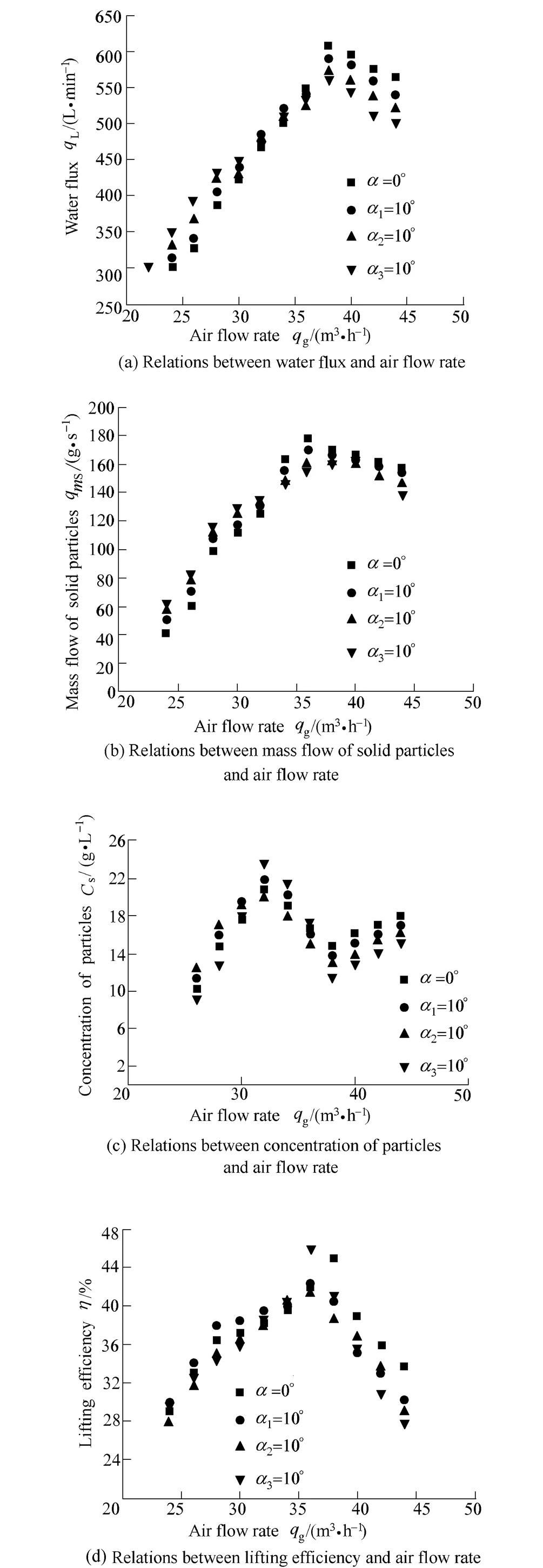
Fig. 7. Performance curves of an air-lift for different injection angle
3.2.3 Performance curves of an air-lift containing arrangement of air injection pipes
In this study, the symbols 3, 4, 5 and 6 are adopted as the different arrangement of air injection pipes. The total height of the lifting pipe and the pipe diameter are the same used in the previous study. The vertical distance, h2+h3,between the water level in the reservoir and the bottom of the lifting pipe is 2 500 mm. The bottom of air injector(namely, the air injection pipe at the bottom) is set at the height of 40 mm above the bottom end of the lifting pipe.
Fig. 8 shows the effect of the arrangement of the air injection pipes on the air-lift performance.
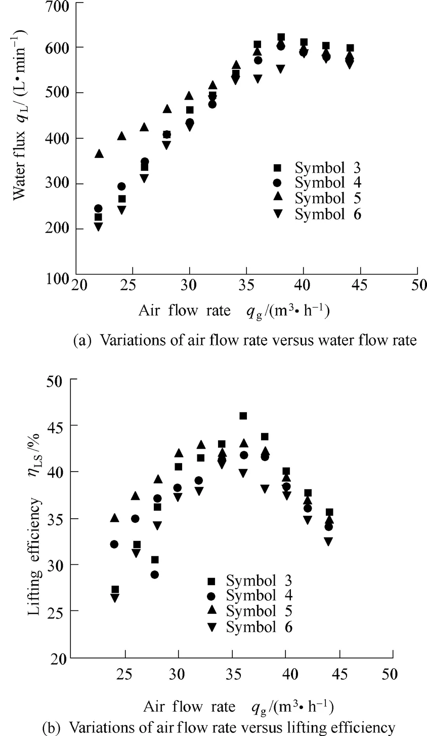
Fig. 8. Performance curves of an air-lift for different arrangement of air injection pipes
It can be seen from Fig. 8(a) that the water flux with using the same length of air injection pipes is smaller than that with different length of air injection pipes at a given low air flow rate (qg≤35 m3/h). Especially the water flux adopting symbol 5 is much larger than that in other three cases. It is dues to the flow pattern, which have great effect on the capability of lifting liquid-solid mixture, when using different length of air injection pipes, the jet cutting car orifice is not in the same plane, the agitated flow has been optimized and the void fraction increases, both of which lead to the uniform distribution of bubble in water. It can also be seen that there is a significant difference for the case of high air flow rate, the lift capacity of symbol 3 is greatly enhanced, and meanwhile, the flow disturbance is obviously intensified in the case of symbols 4 and 5, then the increment of resistance loss in the lifting pipe leads to the attenuation of lift capacity. Here, the symbol 3 has the highest water flux which occurs at an air flow rate of 37 m3/h.
Fig. 8(b) depicts the results obtained for the lifting efficiency versus air flow rate. It is found that the symbol 6 displays the lowest efficiency. There are the highest maximum efficiency of 43.6% for the symbol 5 at the low air flow rate (qg≤33 m3/h) and that value of 46.35% for the symbol 3 at the high air flow rate (qg>33 m3/h). To explain the occurrence of this maximum efficiency (η=46.35%) at an air flow rate of qg=36.5 m3/h in the case of symbol 3, it is noted that this arrangement leads to the creation of bubbles with good initial distribution and suitable size to reduce the slip between air slugs and water, hence, lifting efficiency increases significantly.
4 Conclusions
(1) The performance of the air-lift depends upon several factors, such as air flow rate, number of nozzles, air injection angle and arrangement of air injection pipes. The utilization of three nozzles shows the best performance and the critical value of air flow rate for lifting particles with using three or four nozzles is far less than that with one nozzle used.
(2) The injection angle affects the performance greatly,the maximum lifting efficiency (η=47.12%) occurs at the value of α3=10° and qg=37 m3/h in the case of symbol 3.At a given low air flow rate, the best performance occurs at the angle of α1=10°, but it occurs at α=0° for the high air flow rate. Furthermore, the air injector with different length of air injection pipes has perfect performance at a given low air flow rate (qg≤35 m3/h).
(3) It is also found that the water flux, mass flow of solid particles and lifting efficiency in all cases increase with the air flow rate, firstly reach a peak, and then decrease,however, the concentration of particles—air flow rate characteristics are shown as sawtooth because of the particle feeder supplying a little solid particles. The project research will enrich the theory of borehole hydraulic jet mining.
[1] RUPPEL C, BOSWELL R. Scientific results from gulf of Mexico gas hydrates joint industry project leg 1 drilling: Introduction and overview[J]. Marine and Petroleum Geology, 2008, 25(9):819–825.
[2] XIA Bairu, ZENG Xiping, MAO Zhixin. Research on one borehole hydraulic coal mining system[J]. Earth Science Frontiers, 2008,15(4): 222–225.
[3] WILEY M A. Borehole mining: getting more versatile[J]. Mining Engineering, 2004, 303(1): 33–36.
[4] KATO H, MIYAZAWA T, TIMAYA S, et al. A study of an air lift pump for solid particles[J]. JSME International Journal, 1975,18(4): 286–294.
[5] APAZIDIS N. Influence of bubble expansion and relative velocity on the performance and stability of an airlift pump[J]. Int. J.Multiphase Flow, 1985, 11(3): 459–479.
[6] YOSHINAGA T Y, SATO Y. Performance of an air-lift pump for conveying coarse particles[J]. Int. J. Multiphase Flow, 1996, 22(2):223–238.
[7] LIANG N K. A preliminary study on air-lift artificial upwelling system[J]. Acta Oceanographica Taiwanica, 1996, 35(2): 187–200.
[8] AKIRA Ohnuki. Model development for bubble turbulent diffusion and bubble diameter in large vertical pipes[J]. Journal of Nuclear Science and Technology, 2001, 38(3): 1 074–1 080.
[9] FUJIMOTO H, OGAWA S, TAKUDA H, et al. Operation performance of a small air-lift pump for conveying solid particles[J].Trans. ASME J. Energy Res. Techn., 2003, 125(1): 17–25.
[10] FUJIMOTO H. Effect of local pipe bends on pump performance of a small air-lift system in transporting solid particles[J].International Journal of Heat and Fluid Flow, 2004, 25(3): 996–1 005.
[11] TANG Chunlin, LIAO Zhenfang. Study on air-lift and oscillation pulsed jet in exploiting deep beach placer[J]. Journal of Chongqing University (Natural Science Edition), 1999, 22(3): 79–83.
[12] KHALI M F, ELSHORBAGY K A, KASSAB S Z, et al. Effect of air injection method on the performance of an air lift pump[J].International Journal of Heat and Fluid Flow, 1999, 20(5):598–604.
 Chinese Journal of Mechanical Engineering2010年1期
- Chinese Journal of Mechanical Engineering的其它文章
- Contents and Abstracts of Journal of Mechanical Engineering ISSN 0577-6686, CN 11-2187/TH*
- Measurement of Attenuation of Ultrasonic Propagating through the Thin Layer Media with Time Delay Spectrum
- Analysis and Optimization on Factors Affecting Forming Quality of Half Axle Gears Warm Precision Forging
- Innovation in the Computing System of Straightening Force
- Numerical Method Based on Compatible Manifold Element for Thin Plate Bending
- Investigation on Uniaxial Tensile Instability of USIBOR1500 Steel Sheets at Elevated Temperature
