
An improved initial rotor position estimation method using highfrequency pulsating voltage injection for PMSM
2024-04-11 03:36:08YangJiangMingCheng
Defence Technology 2024年3期
Yang Jiang, Ming Cheng
School of Electrical Engineering, Southeast University, Nanjing 210096, China
Keywords:Initial position detection Signal demodulation algorithm Magnetic polarity detection Filter elimination
ABSTRACT High frequency pulsating voltage injection method is a good candidate for detecting the initial rotor position of permanent magnet synchronous motor.However,traditional methods require a large number of filters,which leads to the deterioration of system stability and dynamic performance.In order to solve these problems,a new signal demodulation method is proposed in this paper.The proposed new method can directly obtain the amplitude of high-frequency current,thus eliminating the use of filters,improving system stability and dynamic performance and saving the work of adjusting filter parameters.In addition, a new magnetic polarity detection method is proposed, which is robust to current measurement noise.Finally, experiments verify the effectiveness of the method.
1.Introduction
In the process of modern industrialization,motors not only play a crucial role in traditional industrial fields, but also contribute to the development of aerospace, transportation, military fields and alike [1,2].Recently, permanent magnet synchronous motors(PMSMs) have attracted widespread attention due to the advantages of high power density,high efficiency,and wide speed range[3,4].In order to achieve high-performance control of PMSM, accurate rotor position information is imperative, which is usually obtained by installing position sensors.However, the use of position sensors increases the cost and system complexity, and it is difficult to maintain or even install position sensors in some special cases [5,6].
Sensorless control technology has been proposed over the past decades, providing opportunities to solve this issue.Sensorless control can basically be divided into two categories: back electromotive force (EMF) based methods and saliency-tracking-based methods.In the medium-high speed domain, back EMF or flux linkage can be obtained by designing the observer or direct calculation.Then, the information of the rotor position is obtained by using the phase-locked loop(PLL)technique[7-10].Unfortunately,the acquisition of both back EMF and flux linkage rely on the accurate mathematical model of PMSM.Therefore,these methods are particularly sensitive to motor parameter variation and inverter nonlinearities.When the motor operates in low speed domain,saliency-tracking-based methods are more advantageous, because of low signal-to-noise ratio(SNR)of back EMF.These methods only rely on the geometric saliency or saturation saliency of motor[11,12].Hence,the rotor position information can be obtained even when the motor is at standstill.
Generally,sensorless control of PMSM at medium-high speed or low speed requires the initial position of the rotor.The wrong initial position may even cause the motor to fail to start or even reverse[13].And, when PMSM needs quickly startup or to be restarted,accurate and fast estimation of initial position is very important and practical [14,15].A large number of saliency-tracking-based methods have been proposed and studied, such as rotating highfrequency sinusoidal voltage injection [16,17], pulsating highfrequency voltage injection [18,19], square-wave high-frequency voltage injection [20-22] and pulse voltage signal injection [23].The method of pulse voltage signal injection is mainly to inject voltage pulse on each phase winding of the motor to detect the response current.Since the magnetic circuit in the north pole direction of the PMSM rotor is more saturated than that in other directions, the inductance in north pole direction is the smallest.Therefore,by comparing the peak value of the current in each phase winding,the phase with the maximum current peak value is closest to the initial position of the rotor.It can be seen that the identification accuracy of the pulse signal injection method is limited and requires complex judgment.Rotating high-frequency sinusoidal voltage injection and pulse high-frequency voltage injection respectively inject corresponding voltage signals into two-phase stationary coordinate system and rotating coordinate system.The initial position information of the rotor can be obtained by demodulating the response high-frequency current.However, the demodulation of the response current usually requires a large number of filters, which increases the order of the system and worsens the dynamic performance of the system.Square wave high-frequency injection can not only have high injection frequency but also eliminate the use of filters, thus improving the dynamic performance of the system.However,in order to ensure a high signal-to-noise ratio,it is necessary to increase the amplitude of the injected voltage,which will limit the bus voltage utilization.In addition, demodulation method of high frequency square wave injection requires the differentiation processing,which is sensitive to current measurement noises[24,25].In addition,a novel method to obtain the initial position of the rotor was proposed by using additional vibration sensors to detect vibration in Ref.[26], and a random signal injection method was proposed to reduce highfrequency noise in Ref.[27].
Unfortunately, continuous signal high-frequency injection method has an angle ambiguity of π [26,27].Therefore, the initial position detection method requires an additional magnetic polarity detection, which are mainly divided into a short pulse injection method and a secondary harmonic based method.Although the method based on the secondary harmonic has fast convergence speed, it has the disadvantage of poor signal-to-noise ratio.Short pulse injection method has better signal-to-noise ratio than secondary harmonic based methods.However, short pulse injection method is still vulnerable to noise.
The main contribution of this paper is to propose a novel signal demodulation method to eliminate the filter in the high-frequency pulsating voltage injection method.The proposed method considers delay compensation and can directly obtain the envelope of high-frequency current without using a filter, thus greatly improving the dynamic performance of the system and save the work of adjusting filter parameters.At the same time, a new polarity judgment method is proposed to enhance the robustness to measurement noise by detecting the area of the falling edge of the response current.The rest of this article is organized as follows.In Section 2, the conventional high-frequency pulsating voltage injection method is modeled and analyzed.In Section 3, the demodulation method is proposed.In Section 4,the novel polarity judgment method is proposed.In Section 5,relevant experimental results are shown to verify the effectiveness of the proposed algorithm.Finally, the conclusions are drawn in Section 6.
2.Analysis of conventional high-frequency pulsating voltage injection methods
In general, the mathematical model of the PMSM in the stationary reference frame (SRF) can be expressed as
with
where subscript h represents that the variable is a high-frequency component.The high-frequency pulse voltage injection method usually injects high-frequency voltage in the δ-axis of the estimated rotary reference frame(ERRF).The relationship between coordinate systems is shown in Fig.1.Therefore, the voltage equation in the ERRF can be expressed as
where Δθ is the angle difference between the RRF and ERRF.To facilitate the research of current response,Eq.(5)can be rewritten as
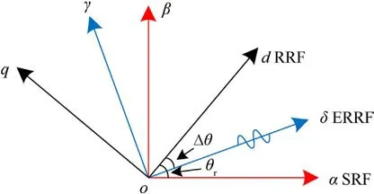
Fig.1.Relationship between coordinate systems.
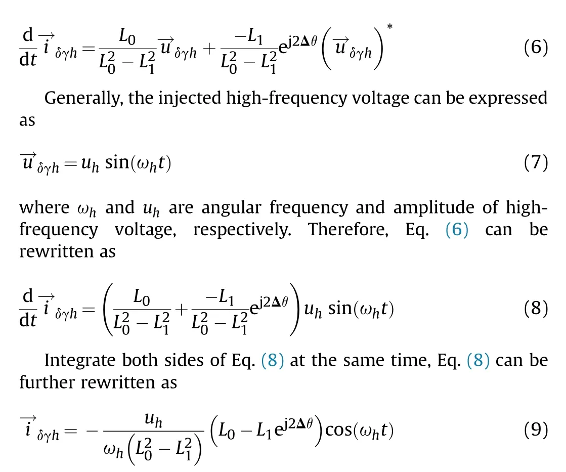
It can be seen that the complex envelope of cos(ωht) contains the information of the position error.Therefore, the key to highfrequency pulse voltage injection method is to effectively extract the complex envelope of cos(ωht).Then, the position angle error can be demodulated from the complex envelope.Eq.(9) can be rewritten as
I want you to have this, Tommy. It ll keep your clothes from getting wet. And before I could mount9 a protest, he had put the thing on me. Thanks, Son. Your mother and I appreciate this.
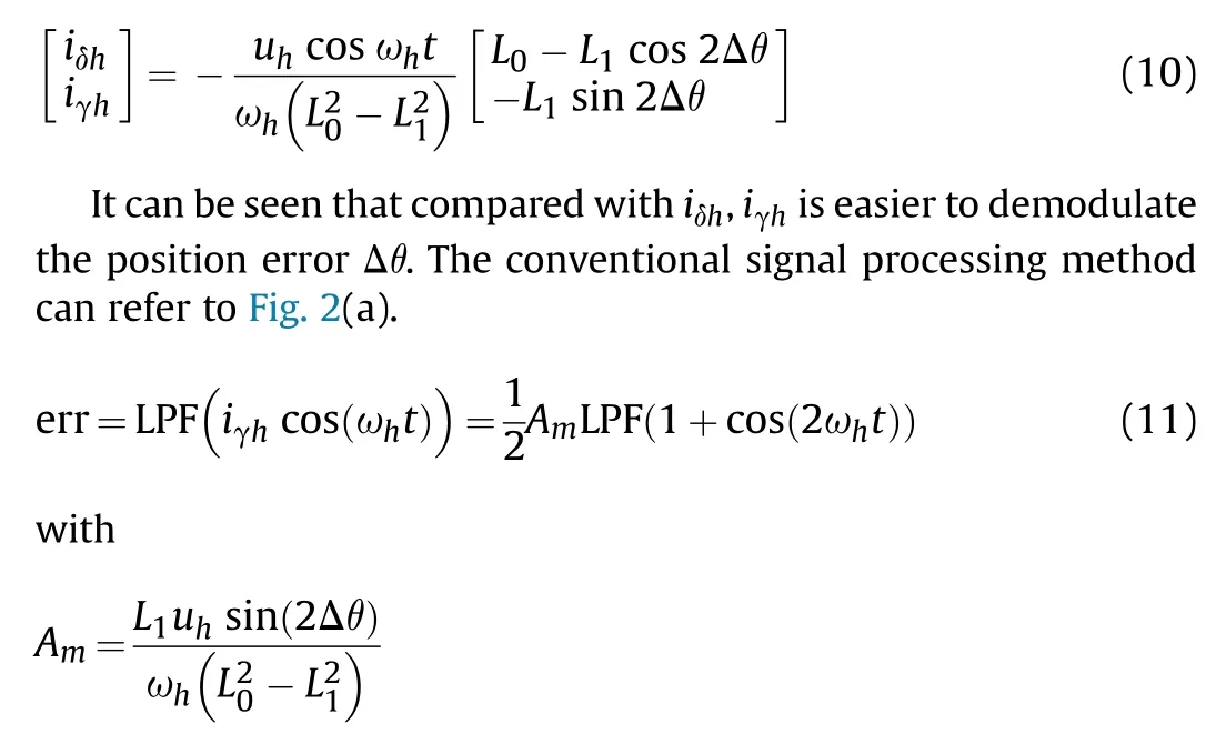
where LPF() is a low-pass filter.Thus, the rotor position can be estimated by adjusting Amto zero through PI controller.
3.Proposed high frequency pulsating voltage injection methods
Although the conventional demodulation method is simple,the problems of long convergence time and possible startup failure still restrict the application of this method.The main reason for these problems is that the filter is used in the conventional demodulation method, which will bring delay and its parameters have great influence on the stability and dynamic performance of the system.This leads to the contradiction between the dynamic performance and stability of the system.Different from the traditional methods,the proposed method eliminates the filter,improving the dynamic performance and stability of the system.
3.1.Proposed signal demodulation method
As mentioned above, the key to pulse high-frequency voltage injection method is to extract the envelope of high-frequency current signal iγh.Therefore, discrete Fourier transform (DFT) can be used to directly obtain the amplitude of high-frequency current iγh.However, DFT increases the computational burden.Therefore,sliding discrete Fourier transform(SDFT)is used in this paper.SDFT utilizes the similarity of signal waveforms between adjacent times,which effectively reduces the amount of computation.The recursive formula of the SDFT is as follows:
where N is the number of sampling points in a SDFT window, n represents the nth discrete time point in a SDFT window, k is the harmonic order of current iγ.Considering the requirement to extract harmonics with an electrical angular frequency of ωhfrom the current iγ.Thus, Eq.(12) must meet the following constraints
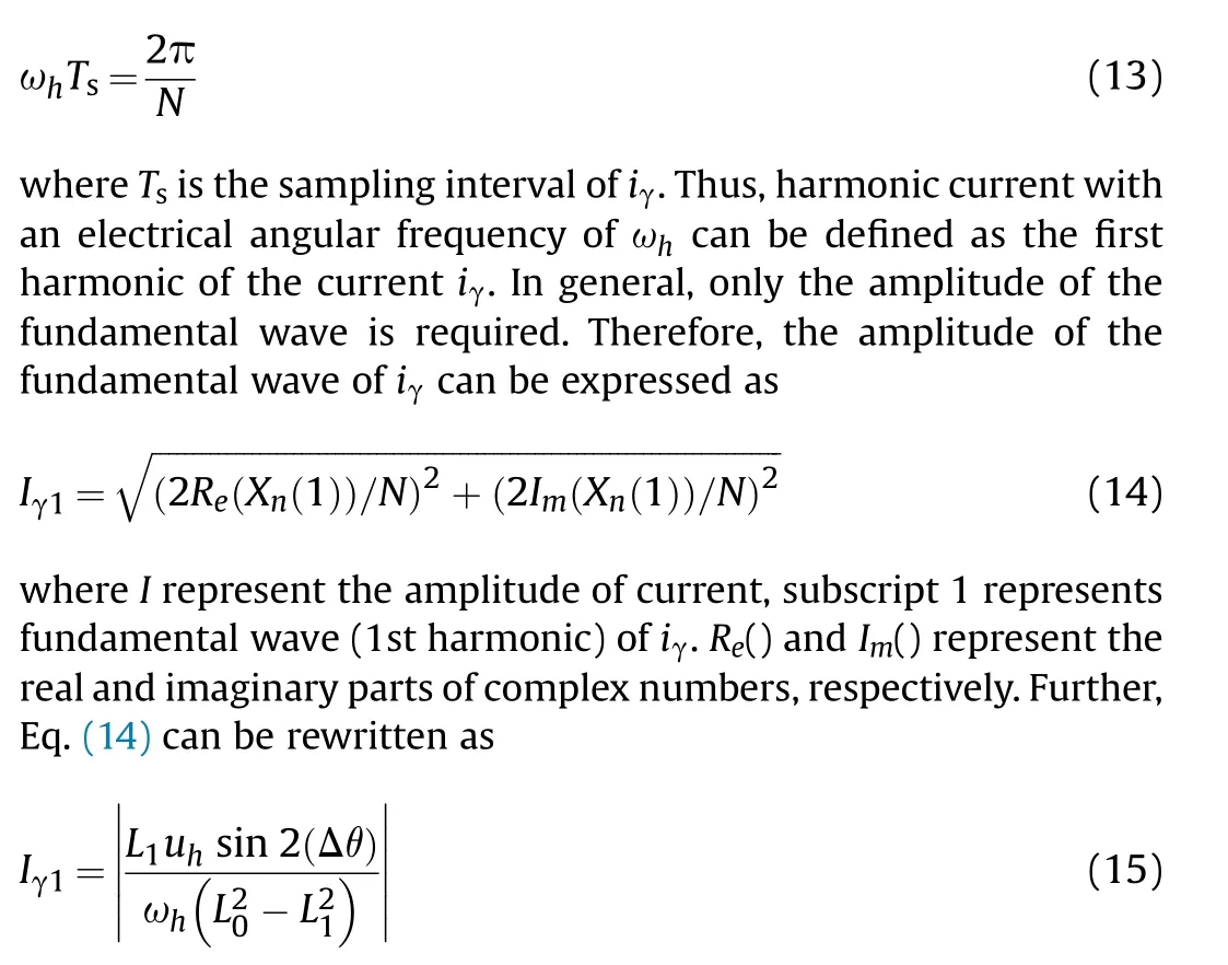
Unfortunately, Iγ1 is always positive and therefore cannot be adjusted by PI controller.Therefore, further processing is required for Eq.(15).According to Eq.(10),when Δθ>0,the phase difference between iγh and cos ωht is π and when Δθ<0,the phase difference between iγhand cos(ωht)is 0.Therefore,the sign of amplitude can be judged by the phase difference between iγh and cos ωht.According to the principle of inverse Fourier transform,iγ1satisfies the following equation.
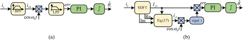
Fig.2.Comparison of signal processing methods: (a) Conventional method; (b) Proposed method.

where sign()represents the sign of a variable.The proposed signal processing method can refer to Fig.2(b).The proposed signal processing method eliminates the band-pass filter and low-pass filter in conventional methods.And because of using recursive formula to solve DFT, the computational burden is greatly reduced.
3.2.Delay compensation
As mentioned above, the sign of amplitude is judged by the phase difference between iγhand cos(ωht).Ideally, the phase difference between iγhand cos(ωht) is 0 or π.Unfortunately, the unavoidable delay exists in the actual system.The timing execution sequence of a control cycle in this paper is shown in Fig.3,including PWM update, current sampling and control calculation.At the beginning of the current control cycle,the duty cycle calculated in the previous cycle is used to update the PWM.Subsequently, the present current is obtained through the current sampling module.Finally, control algorithms are calculated, including coordinate transformation, sensorless control algorithm, space vector pulse width modulation(SVPWM)algorithm and so on.Therefore,it can be concluded that the current measured at k is obtained under the action of voltage calculated at k-2.To facilitate analysis,the forward difference equation of Eq.(8) can be expressed as
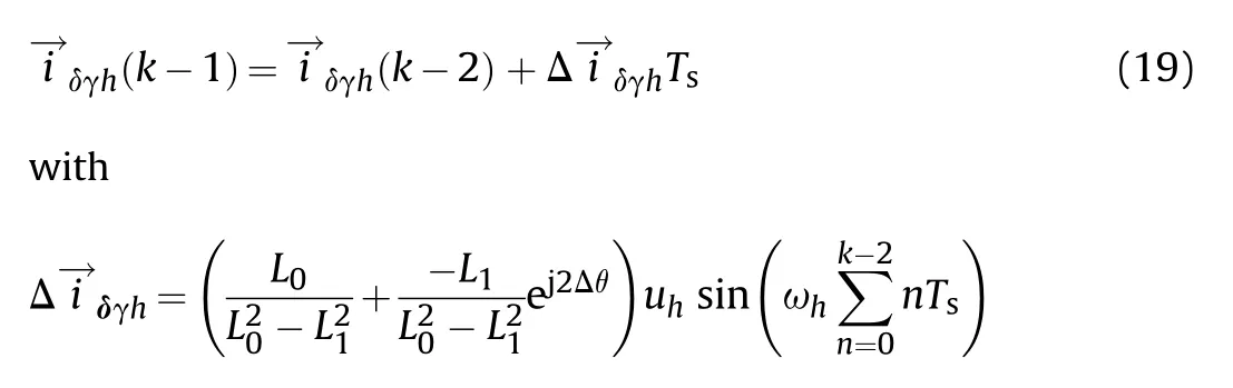

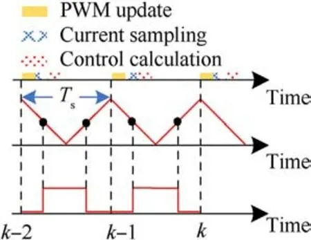
Fig.3.Sequence diagram.

In fact, in addition to the delay caused by the time sequence of discrete system execution, the dead time of inverter, the uncertainty of motor modeling, and the time required for algorithm execution will also cause phase delay.The existence of delay leads to the error of amplitude sign judgment.Therefore, in order to avoid this situation, this paper proposes an amplitude sign judgment method, which can refer to Fig.5.The main idea of this algorithm is to introduce the sign of the amplitude of the previous cycle to assist in judging the sign of the amplitude of the current cycle.For example,when the amplitude of the kth cycle is negative but the amplitude of the k-1 cycle is positive,the amplitude of the kth cycle is considered positive.When the sign of the amplitude of the k+1 cycle is still negative,the sign of the amplitude of the k+1 cycle is considered negative.This can effectively avoid the sign judgment error caused by uncertain delay.
4.Proposed polarity judgment
When the PMSM rotates for one cycle, the inductance will undergo two cycles of change.Therefore, the estimated position information has an angle ambiguity of π.The short pulse voltage injection method is a very effective method for polarity judgment.When the estimated initial position ^θris obtained, two voltage pulses with the same amplitude and time length but different sign are injected in sequence along the initial position ^θr.The air gap flux linkage of PMSM is a composite flux linkage formed by permanent magnet flux linkage and stator winding induction flux linkage in the air gap.Therefore, when the excitation flux linkage and the permanent magnet flux linkage are in the same direction,the amplitude of the resultant flux linkage becomes larger,causing the inductance to enter the saturation region.On the contrary,when the directions of the excitation flux and permanent magnet flux are reversed, the amplitude of the resultant flux becomes smaller,leading to the inductance entering the linear region,which can refer to Fig.6.
The main idea of the traditional polarity detection method is that when the magnetic circuit is saturated, the inductance becomes smaller and the peak value of the response current becomes larger.On the contrary, when the magnetic circuit is unsaturated,the inductance becomes larger, so the peak value of the response current becomes smaller.Therefore,the direction of the north pole of the PMSM can be determined by detecting the response current and comparing their peak values.However, it is obvious that this requires high accuracy of the current sensor.
In this paper,a method is proposed to determine the polarity of PMSM by calculating the area of the falling edge of the response current.As is shown in Fig.7(a),tris the time of the falling edge of the response current generated by the voltage pulse with the same injection direction as the north pole of PMSM.On the contrary,tdis the time of the falling edge of the response current generated by the voltage pulse with the same injection direction as the south pole of PMSM.Obviously, tris less than td, because different inductances cause different time constants.Therefore,S1is less than S2, S represents the integral of the falling edge of the response current with respect to time.Thus, the initial position ^θris the actual position when S1is less than S2.Similarly,the opposite case is shown in Fig.7(b).Thus,the difference between the initial position^θrand the actual position is π when S1is greater than S2.The proposed method does not directly detect the amplitude of the two response currents,but judges the polarity by comparing the area of the falling edge of the two currents.Therefore, the proposed method effectively improves the signal-to-noise ratio compared with traditional methods.

Fig.4.The proposed signal processing method.
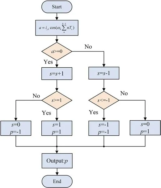
Fig.5.Flow diagram.
5.Experimental verification
In this section, the experimental results of an improved initial rotor position estimation method using HF pulsating voltage for PMSM is presented to verify the effectiveness of the proposed algorithm.The specific parameters of the PMSM can refer to Table 1.Fig.8 shows the experimental platform and controlled motor.Then,Fig.9 shows the structure diagram of this proposed method.In this experiment,DSP TMS320F28377D is chosen as control chip,which has a clock frequency of 200 MHz.The basic experimental configuration is bus voltage 60 V and switching frequency 10 kHz.The incremental position sensor is applied in the experiment.To verify the robustness of the proposed method to current noise, two different current sensors are selected to sample three-phase current.The one with a range of 8 A and low noise,and the other with a range of 50 A and high noise.The current sensor with low noise is named as Current Sensor 1, while the current sensor with high noise is named as Current Sensor 2.Then, the DSP obtains current information through analog-to-digital conversion chip 7606 CE.Meanwhile, the sampling frequency and control frequency is consistent with the switching frequency.
5.1.Performance verification
In this part, the main experimental results are presented to verify the effectiveness of the proposed algorithm.In the experiment, the frequency of injected high-frequency voltage is 1 kHz,and its amplitude is 20 V.It is worth noting that the amplitude of the injected voltage should ensure the signal-to-noise ratio of the response current.In addition,the amplitude of the injected voltage should not be too large to prevent the motor from experiencing significant shaking, which can worsen the estimation of the initial rotor position.According to Eq.(13), one cycle of high-frequency voltage with frequency of 1 kHz requires 10 sampling points.Therefore,N is set to 10.
The first experiment mainly shows the steady-state performance of the proposed demodulation algorithm, as shown in Fig.10.In this experiment, the actual initial rotor position of the PMSM is in the same direction as the A-phase winding (θr= 0),which can be achieved by directly setting the duty cycle to (100).The values of the estimated initial position^θrare respectively set as π/3 in Fig.10(a) and -π/3 in Fig.10(b).As shown in Figs.10(a) and 10(b), in steady state, the waveform of measured current iγ has slight distortion,which is caused by inverter dead time and PMSM nonlinearity.The waveform of current iγ1obtained by proposed demodulation algorithm is symmetrical and the distortion is relatively small.Moreover, its amplitude and phase have little difference with iγ.Therefore,the proposed demodulation algorithm can replace the band-pass filter.The absolute value of err is the amplitude of the iγ1obtained by the proposed method.It can be seen that the waveform of err is stable and its absolute value is equal to the amplitude of iγ1.Therefore,it can be concluded that the proposed demodulation algorithm has excellent steady-state performance, and can replace the band-pass and low-pass filters in conventional algorithms.
The second experiment mainly shows the dynamic performance of the proposed demodulation algorithm, as shown in Fig.11.In Fig.11(a),^θrswitches from-π/3 to π/3,which can be considered as a step given.The dynamic performance of the system can be judged by examining the step response of the system.It can be seen that err changes from -0.18 A to 0.18 A within 500 μs, which has a satisfactory step response speed.Similarly,in Fig.11(b),err changes from 0.18 A to -0.18 A within 500 μs, when ^θrswitch from π/3 to-π/3.Therefore, the proposed demodulation algorithm offers excellent dynamic performance.
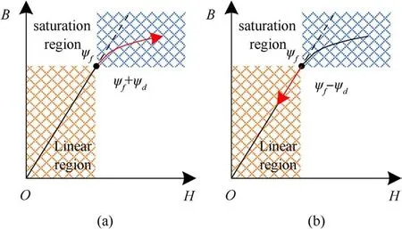
Fig.6.D-axis magnetic circuit B-H Characteristic curve: (a) D-axis magnetic circuit saturation; (b) D-axis magnetic circuit unsaturated.
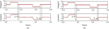
Fig.7.Polarity judgment: (a) Injecting pulse voltage along the north pole direction of PMSM; (b) Injecting pulse voltage along the south pole direction of PMSM.
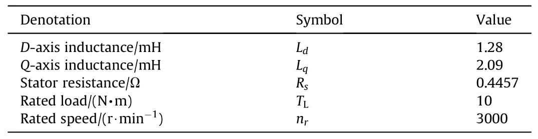
Table 1 Parameters of PMSM.
The third experiment shows the whole process of initial position identification.Firstly,the initial position of the rotor θris estimated by pulse high-frequency voltage injection method.Meanwhile,there is ambiguity of π between the estimated^θrand θr.Thus,after the high frequency pulse voltage injection method is completed,two pulse voltages with the same amplitude (10 V) and different sign values are injected along direction of the estimated position.The calculation of the falling edge area is completed by accumulating the current during the period of the falling edge.For the first injection voltage, when the voltage switches to zero, the accumulation of current begins to be executed.The duration of this current accumulation is obtained through experimental testing.Similarly,when the second injection voltage switches from-10 V to zero,the DSP begins to accumulate the current.Then,the accumulated value of the two currents will be used to compare sizes.Then,the correct initial position can be obtained according to the proposed polarity judgment method.In Fig.12(a),actual initial position θris zero rad,and the initial value of the estimated position ^θris 1 rad.It can be observed that the estimated position ^θrcan converge to the actual position of the PMSM within 5 ms.In the following polarity judgment process, it is obvious that the area of the falling edge of the positive current is smaller than the area of the falling edge of the negative current.Therefore, the current estimated position does not require π correction.Similarly, in Fig.12(b), actual initial position θris still zero rad.However, the initial value of the estimated position^θris set to 2 rad.The estimated position^θrcan converge to θr+π within 5 ms.The area of the falling edge of the positive current is greater than the area of the falling edge of the negative current.Thus, the estimated position needs to subtract π.Fig.13 shows the initial position estimation error, when the estimated position^θrtakes different initial values and θris equal to zero.The position estimation error is within 4°, which proves that the proposed method has high accuracy.
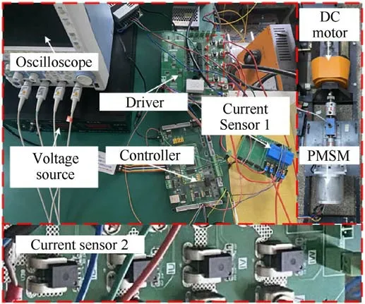
Fig.8.Experimental platform.
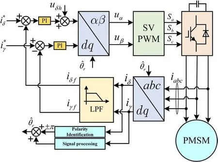
Fig.9.Structure diagram of an improved initial rotor position estimation method using HF pulsating voltage for PMSM.
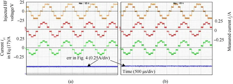
Fig.10.Measured steady-state current waveforms of proposed method: (a) θr = 0 rad, ^θr = π/3 rad; (b) θr = 0 rad; ^θr = -π/3 rad.
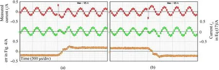
Fig.11.Measured dynamic current waveforms of proposed method.(a) θr = 0 rad, ^θr = π/3 rad; (b) θr = 0 rad, ^θr = -π/3 rad.
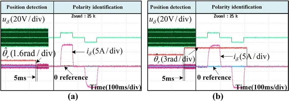
Fig.12.The whole process of initial position identification: (a) θr = 0 rad, ^θr =1 rad; (b) θr = 0 rad, ^θr = 2 rad.
5.2.Comparison experiment
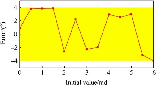
Fig.13.Estimated position error.
In this part,the experimental results are compared with those of conventional method to verify the effectiveness of the proposed algorithm.In the first experiment, the proposed demodulation algorithm is compared with the conventional method using a lowpass filter.The bandwidth of the low-pass filter is set to 30 Hz,100 Hz and 300 Hz,respectively.In Fig.14,err represents Input of PI controller.Meanwhile, according to Eq.(11), the absolute value of err obtained by conventional method is half of the amplitude of high-frequency current.Thus,to facilitate comparison,err obtained by conventional methods is doubled here.In this experimental, ^θrswitches from-1 rad to 1 rad and θris equal to zero,which can be considered as step given.As shown in Fig.14(a),it can be observed that the step response speed of the proposed method is much faster than that of the conventional method where bandwidth of lowpass filter is set at 30 Hz.Meanwhile, the steady-state performance of the proposed method is equivalent to that of conventional methods.In Fig.14(c), the dynamic performance of the proposed method is similar to that of the conventional method with 300 Hz bandwidth.However,due to the improvement of the bandwidth of the low-pass filter, it is unable to effectively filter out highfrequency signals.Therefore, the err obtained by conventional methods has a 2 kHz frequency fluctuation.However,the proposed method still has excellent steady-state performance.Thus,it can be concluded that the dynamic performance of the proposed method can match that of conventional methods with 300 Hz bandwidth.However, its steady-state performance is better than conventional methods.
The second experiment compares the convergence speed of the proposed method, the conventional method and square wave injection method under the condition that the parameters of the PI controller are the same, where kpand kiare set to -2000 and 0,respectively [6].In addition, for the fairness of comparison, the steady-state performance of the three methods should be the same.Thus,the low-pass filter bandwidth in the conventional method is 30 Hz.Meanwhile,the injection voltage frequency of the proposed method and conventional method is 1 kHz,while that of the square wave injection method is 5 kHz,which is half of the switching cycle.Then, the amplitude of the injection voltage for three methods is 20 V.As shown in Figs.15(a)and 15(c),the convergence time of the proposed method is about 4 ms,however,the convergence time of conventional methods is about 20 ms.In addition,the steady-state performance obtained by the two methods is the same.It can be concluded that the proposed method requires much less convergence time than the conventional method.In addition, Fig.15(b)shows the experiment results that the convergence time of square wave injection method is about 5 ms.Therefore, the rate of convergence of the proposed method is faster than that of the square wave injection.
Usually, the initial position detection method based on highfrequency injection can be directly applied to low-speed sensorless control.Thus, the third experiment compares the sensorless control performance of the proposed algorithm and square wave injection under low speed.In this experiment,the reference speed is set to 50 r/min, and switches to -50 r/min when the motor reaches steady state.Then,the injected voltage of proposed method is a sine wave of 1 kHz and 20 V,and that of square wave injection method is a square wave of 1 kHz and 20 V.In addition, the parameter settings for PI control in both methods are the same,where kp and ki are set to-400 and-2000.In Fig.16,it can be seen that both methods will have estimation errors in position when the motor reference speed is switched from 50 r/min to -50 r/min.Then, when the motor reaches steady state,the error between the estimated motor position and the actual motor position will decrease.In addition, the proposed algorithm reduces position error faster under the same conditions of bus voltage and PI controller parameters.
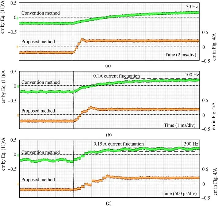
Fig.14.Bandwidth test: (a) 30 Hz; (b) 100 Hz; (c) 300 Hz.
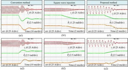
Fig.15.Comparative experiment of dynamic performance: (a) Conventional method; (b) Square wave injection; (c) Proposed method; (a1)-(c1)θr = 0 rad, ^θr =1 rad.(a2)-(c2)θr = 0 rad, ^θr = 2 rad.

Fig.16.Comparative experiment of sensorless control in low speed: (a) Square wave injection; (b) Proposed method.
In the last experiment,the experimental results of the impact of noise on the proposed algorithm and square wave injection method will be presented.In the experiment, two current sensors with different ranges will be used.The range of Current Sensor 1 is 8 A and there is less noise,while the range of Current Sensor 2 is 50 A and has high noise.Fig.17 shows the sampling noise of two current sensors when the motor is stationary.Previous experimental results were obtained by using Current Sensor 1.Then,Current Sensor 2 will be used in this last experiment.Considering that current noise is usually concentrated in the high-frequency range, for the fairness of experimental comparison,the frequency of the injected square wave voltage is 1 kHz, which is the same frequency as the injected sine wave.Meanwhile, the amplitude of the injected sine wave and the injected square wave is 20 V.As shown in Fig.18(a),the influence of noise on square wave injection method is obvious.The waveform of err fluctuates greatly,where err in Fig.18(a)is the input of the PI controller in the square wave injection method.However,it can be observed that there are small fluctuations in the waveform of err of proposed method in Fig.18(b).It can be concluded that current noise has a smaller impact on the proposed method compared to square wave injection method.
6.Conclusions
This paper proposes an improved initial rotor position estimation method using high-frequency pulsating voltage injection for PMSM.Compared with the conventional method, the proposed method does not require the use of filters.Therefore,the proposed method has better dynamic performance.In additional, compared with square wave injection method, this proposed method has stronger robustness to current noise.Meanwhile, the proposed method has also achieved satisfactory results in low-speed sensorless control compared with square wave injection method under the same conditions.Moreover, this proposed method contains a magnetic polarity detection method with strong robustness to current noise.The experimental results show that in terms of dynamic performance,the proposed method can be equivalent to the conventional method of setting the low pass filter frequency to 300 Hz.Meanwhile, the proposed method also has excellent steady-state performance.Therefore, the proposed method can improve the dynamic performance of the system and save the work of adjusting filter parameters.
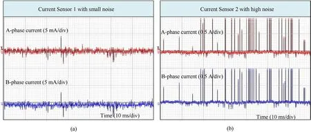
Fig.17.Experiment results of noise measurement: (a) Current Sensor 1; (b) Current Sensor 2.

Fig.18.Robustness experiment against noise using current Sensor 2: (a) Square wave injection; (b) Proposed method.
Declaration of competing interest
The authors declare that they have no known competing financial interests or personal relationships that could have appeared to influence the work reported in this paper.
Acknowledgments
This work was supported by the National Natural Science Foundation of China under Grant 51991384 and Anhui Provincial Major Science and Technology Project under Grant 202203c08020010.

- Defence Technology的其它文章
- Evolution of molecular structure of TATB under shock loading from transient Raman spectroscopic technique
- MTTSNet:Military time-sensitive targets stealth network via real-time mask generation
- Vulnerability assessment of UAV engine to laser based on improved shotline method
- Free-walking: Pedestrian inertial navigation based on dual footmounted IMU
- Investigation of hydroxyl-terminated polybutadiene propellant breaking characteristics and mechanism impacted by submerged cavitation water jet
- Estimation of surface geometry on combustion characteristics of AP/HTPB propellant under rapid depressurization