
Research progress on construction strategy and technical evaluation of aircraft icing accretion protection system
2023-11-10 02:16:48QingHEKngshuiLIZehuXUJiwenWANGXiosenWANGAnlingLI
CHINESE JOURNAL OF AERONAUTICS 2023年10期
Qing HE, Kngshui LI, Zehu XU, Jiwen WANG, Xiosen WANG,Anling LI,*
a College of Civil AviationSafety Engineering, Civil Aviation Flight University of China, Guanghan 618307, China
bKey Laboratory of Icing and Anti/De-icing, China Aerodynamics Research and Development Center, Mianyang 621000, China
c Henan Joint International Research Laboratory of Man Machine Environment and EmergencyManagement,Anyang 455000,China
KEYWORDS
Abstract The impact of unstable supercooled water droplets suspended in the cloud on the solid will cause its surface to freeze, and the flight safety of the aircraft will be seriously affected when flying in this environment.Aircraft icing protection system is an important device to reduce icing accidents and improve aircraft safety performance, which is of great significance to ensure flight safety.Based on the energy source, this paper proposes a general strategy for constructing an aircraft icing protection system,including Active Anti-icing and De-icing(AAD)system,Passive Antiicing and De-icing(PAD)system and Composite Anti-icing and De-icing(CAD)system.The principle, scope of application, advantages and disadvantages of aircraft anti-icing and de-icing technologies such as electric pulse de-icing, low-frequency piezoelectric de-icing, and hydrophobic material anti-icing are explored in detail, and the corresponding improvement measures are proposed.The future development of aircraft anti-icing and de-icing technology is prospected, and some new ideas are provided for the improvement of aircraft anti-icing and de-icing technology.
1.Introduction
When an aircraft encounters a cloud layer containing supercooled water droplets with a temperature of 0 °C to -20 °C during flight, the water droplets will accumulate on the body in the form of ice, thereby affecting the aerodynamic characteristics of the aircraft and jeopardizing flight safety.1Ice accretion usually occurs on the exposed front surface of the aircraft, and the parts seriously affected by icing include wings,2,3rotors,4,5engines,6,7etc.According to the analysis of the causes of aircraft accidents in recent years,aircraft icing is the main external cause of aircraft accidents, and the resulting flight accidents have attracted more and more attention,especially the launch of some major aircraft projects, making the research related to aircraft icing a hot spot.8–10At present,the research on aircraft icing mainly focuses on icing on the wings,because it can have serious adverse consequences.When the wing freezes, the change in the airfoil shape can lead to a decrease in lift and an increase in drag,which may cause flight accidents.11,12Therefore, the research of aircraft ice accretion protection system is a problem that must be considered in aircraft research and development.
With the rapid development of modern aircraft technology,in order to ensure the flight safety of the aircraft in the cloud layer containing supercooled water droplets, researchers have used numerical model simulation,13,14icing wind tunnel experimental verification15,16and other technologies to develop some effective ice protection systems.According to their different construction strategies, ice protection systems are divided into Active Anti-icing and De-icing (AAD) system, Passive Anti-icing and De-icing (PAD) system and Composite Antiicing and De-icing(CAD)system.Current technologies for aircraft anti-icing and de-icing systems include electrical pulse deicing,17low-frequency piezoelectric de-icing,18pneumatic deicing,19ultrasonic de-icing,20,21hot air anti-icing and deicing,22electro-thermal anti-icing and de-icing,23,24anti-icing of hydrophobic material,25plasma anti-icing,26,27synthetic jet anti-icing,28memory alloy de-icing,29electro-thermal hydrophobic material anti-icing and de-icing,30etc.With the deepening of the research on the existing aircraft icing protection system, the defects of its complex testing equipment and low efficiency are gradually revealed.Therefore, it is particularly important to develop a simple, high-efficiency, green,low-energy-consumption, multi-functional and stable aircraft anti-icing and de-icing system.
Based on the existing aircraft icing protection system, this paper expounds the overall strategy of constructing the aircraft icing protection system in detail, focuses on the research progress of the current aircraft commonly used anti-icing and de-icing technology,summarizes the advantages and disadvantages of the existing aircraft anti-icing and de-icing technology research, and prospects the future development direction of aircraft anti-icing and de-icing technology.The purpose is to let relevant scholars have a comprehensive and rapid understanding of aircraft anti-icing and de-icing technology, and provide ideas and methods for the development of new aircraft anti-icing and de-icing systems.
2.Overall strategy for building an aircraft icing protection system
When the aircraft is flying under the cloud layer of unstable supercooled water droplets, water droplets accumulate on the surface of the aircraft in the form of ice.Table 1 shows the common aircraft types of ice accretion and its meteorological causes and main locations.31To prevent some parts of the aircraft from freezing, it is necessary to adopt an appropriate aircraft icing protection system to ensure the flight safety of the aircraft.The existing aircraft icing protection systems can be divided into anti-icing systems and de-icing systems according to whether there is an ice layer on the surface of the aircraft.The anti-icing system refers to the use of heating or hydrophobic coating to prevent aircraft surface parts from icing;the de-icing system allows a small amount of ice to form on the aircraft surface and then remove it before the icing has a significant adverse effect.
Due to the precision of the aircraft structure, the design of the aircraft icing protection system should meet the anti-icingand de-icing requirements of the entire aircraft.When designing an aircraft icing protection system, some typical status points are usually selected, and the load and energy consumption of the aircraft anti-icing and de-icing system are determined according to these typical status points.The state point of the anti-icing system includes the flight status of the aircraft and the icing meteorological conditions.By selecting the typical flight state of the aircraft, and according to the meteorological design specification of anti-icing and de-icing system, the icy meteorological conditions of aircraft are determined.Finally, the minimum energy required and the overall design of the anti-de-icing system are further determined according to the limiting conditions.32Meier and Scholz33took Boeing 787 as an example to estimate the power of Boeing 787 by deducing the comprehensive technical parameters of the electric de-icing system, which greatly simplifies the calculation process of the load of the anti-icing and de-icing system.Hann et al.34carried out anti-icing and de-icing experiments on the electrothermal anti-icing and de-icing system in the icing wind tunnel, and determined the most energy-saving anti-de-icing method by studying the parameters of melting time.In addition, the severity of icing on different parts of the aircraft surface is different, and the degree of influence on the aerodynamic performance and stability of the aircraft is also different.A reasonable design of the protection area can greatly reduce the energy consumption of the system and increase the load rate of the engine.Therefore,it is very important to develop a multi-functional,stable and fast-response ice accretion protection system.This paper summarizes in detail three existing general strategies for constructing aircraft icing protection systems: AAD system, PAD system, and CAD system.
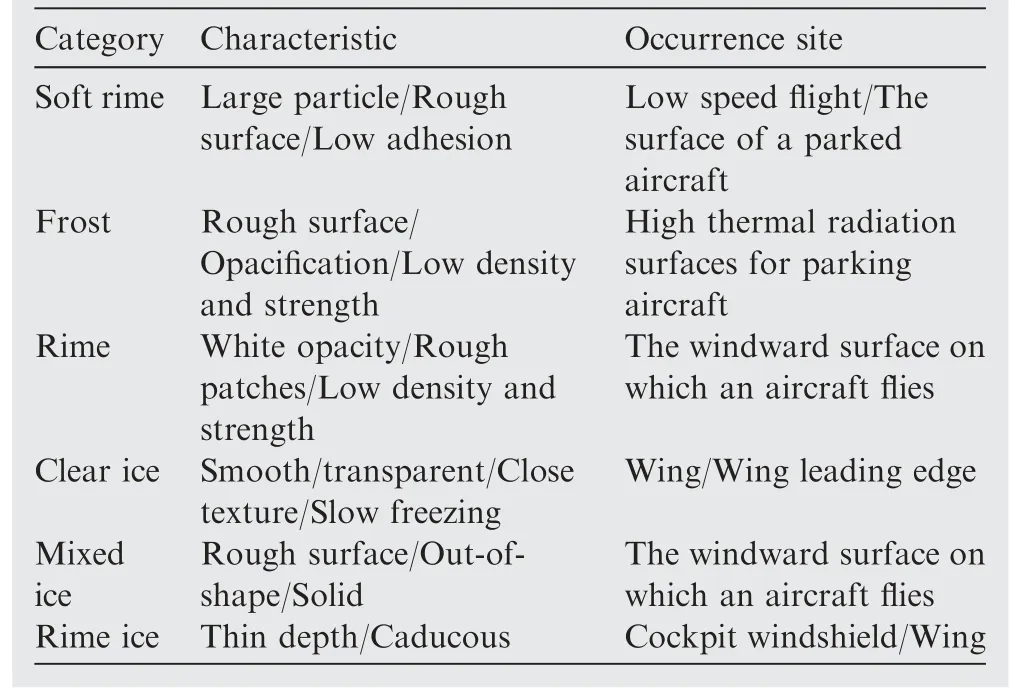
Table 1 Several common types of icing on aircraft, their meteorological causes and main locations.31
2.1.AAD system
AAD systems use energy from external systems for the purpose of keeping the aircraft safe.Thermal methods are the most widely used method in AAD systems, which use heat to raise surface temperatures to prevent icing and to melt the ice.The heat can come from hot air from the engine35or electric heaters embedded under the surface of the wing.36The method ensures the flight safety of the aircraft in icing conditions, but energy consumption has been the main topic of discussion.Due to the relatively high cost of thermal energy methods and the limitation of experimental conditions,researchers usually choose numerical simulation studies.35Wright37calculated a representative value of the heat transfer coefficient and applied it to a piccolo tube system with temperature data.The experimental results showed that the method overestimated the surface temperature, resulting in a different shape of the ice remnant than the experimental shape.Zhou et al.38proposed a method for predicting the surface temperature and backflow ice of a 3D thermal gas anti-icing and deicing system.Based on this method, it was concluded that the influence of liquid water content and Mach number is much larger than that of the external flow temperature.
At present,the substandard experimental parameters of different numerical simulation studies lead to large errors in the experimental simulation results.Therefore, it is necessary to improve the numerical simulation software of aircraft icing and to divide the experimental conditions more precisely to achieve the accuracy of system performance prediction.Papadakis and Wang39used the Navier-Stokes equation to calculate and study the effects of diffuser geometry, hot air temperature and mass flow on system performance.In addition,the team developed and designed an optimization simulation tool for the hot air anti-icing and de-icing protection system, and based on this, the influence of hot air mass flow and hot air temperature on the wing skin temperature was studied.40Pourbagian and Habashi41first studied the effects of parameters such as surface temperature, ambient temperature, airspeed and angle of attack on the energy consumption of aircraft anti-icing and de-icing systems.In addition, the team conducted a parameter sensitivity analysis to conduct a parametric study of the energy consumption of the aircraft anti-icing and de-icing system.Zhang et al.42studied the influence of structural parameter uncertainty on the thermal efficiency of the anti-icing cavity of aircraft wings, and found that the height of the double-layer channel and the diameter of the jet hole are the core factors affecting the functional reliability of the anti-icing cavity.In addition to optimizing the icing protection system on the wing, researchers also optimize the icing protection system on the engine by improving techniques such as numerical simulation software.43–46
Mechanical force is one of the common methods used in AAD systems, where the ice is broken up and removed by applying mechanical force on the accumulated ice.One of the representative mechanical force anti-icing and de-icing methods is pneumatic de-icing, which works by setting many expandable rubber tubes under the surface of the leading edge of the wing.When the surface of the aircraft freezes,the rubber tubes inflate and expand to break the ice, and then use the air flow to blow the ice away.Helicopters use pneumatic de-icing due to their poor load-bearing capacity and limited power sources.47Compared with the thermal energy method,the system has the advantages of light weight,high practicability and low cost.In addition, since pneumatic de-icing can only remove the ice accretion after the ice accretion thickness is greater than the threshold, it has the disadvantage of low efficiency and cannot be removed when the ice accretion is thin.The electromechanical pulse de-icing technology uses the electric pulse generated by the internal coil of the wing to excite the high-frequency oscillation of the wing skin to remove the ice,which solves the problem of thin ice layer during the flight of the aircraft.Mo¨hle et al.48used finite element simulation to analyze the magnetic field and structure coupling of the electric pulse de-icing process.Based on this method, the de-icing process of the electric pulse system could be simulated accurately, and the de-icing conditions under different icing thickness could be predicted accurately.With the deepening of the research, the researchers’ research on the electric pulse system is gradually refined, and the factors considered are more comprehensive.Many researchers49,50have studied the coil problem and analyzed in detail the influence of the number of coils,diameter of coils, arrangement mode and start-up time on the de-icing device, providing a basic idea for the future research and design of electric pulse system.
In addition to thermal energy method and mechanical force method, chemical method is also one of the important technologies of AAD system.Chemical methods reduce ice adhesion by exploiting the chemical properties of substances to avoid ice on aircraft surfaces.Corsi et al.51tested the biochemical oxygen demand and chemical oxygen demand of icing inhibitors, and tested the degradation rate of different deicing formulations in seawater.While chemical methods have been used in anti-icing and de-icing technology, these chemicals often have corrosive properties that can destroy the aerodynamic properties of aircraft surfaces and even cause irreversible damage to the environment.Therefore, the search for a green and pollution-free chemical substance is a field worthy of attention52.Since benzotriazoles have the properties of inhibiting metal corrosion,researchers have focused on benzotriazoles in the study of the environmental impact of icing inhibitors.53Wolschke et al.54studied the distribution of benzotriazoles and other organic compounds in different estuaries in Central Europe and the North Sea, and tested their pollution characteristics to rivers.
The AAD system uses thermal energy method and mechanical force method to remove the ice layer in time after finding the icing.It has quick response and can eliminate the icing problem in different degrees to ensure flight safety.However,under certain conditions, the melted ice layer will cause secondary icing and lead to the formation of nodular ice, which has a great impact on the aerodynamic performance of the aircraft.
2.2.PAD system
PAD systems reduce the ice adhesion on the aircraft surface by changing the hydrophobicity of the aircraft surface,or use the properties of memory alloys to deform the ice layer to achieve the purpose of anti-icing/de-icing.Li et al.55studied the selfcleaning and delayed icing properties of the superhydrophobic composite membrane, and the experimental results showed that the composite membrane had excellent delayed icing performance.Although the development of hydrophobic materials has been studied for decades, the study of the durability of hydrophobic coating surfaces is particularly important due to the instability of the surface microstructure of hydrophobic materials.56–59Xue et al.60placed the hydrophobic sample flat on the sandpaper, and then used a weight of 100 g to conduct the sandpaper abrasion resistance test on its surface.The test process and results are shown in Fig.1(a).In addition,durability experiments such as ultraviolet irradiation, chemical etching and artificial friction were also carried out on the hydrophobic samples.The experimental results show that the hydrophobic material has a strong ability to resist harsh environments.Zhuang et al.61conducted water droplet impact experiments on hydrophobic composites, and used contact angle combined with SEM to analyze the changes in surface hydrophobicity after impact(Fig.1(b)).In addition,atmospheric durability tests such as abrasion resistance test,tape peeling test and ultraviolet resistance test were also carried out, simulating the real environment of the aircraft flying in the air.The experimental results show that the hydrophobic composite exhibits excellent stability.Zhu et al.62fabricated a transparent superhydrophobic coating with mechanochemical stability and reversible wettability,verified the mechanical stability of the coating with adhesive tape, and tested its hydrophobicity in extreme pH environment.The transparent superhydrophobic coatings prepared based on this method are resistant to various mechanical and chemical attacks and exhibit excellent performance in anti-icing and de-icing and self-cleaning.Li et al.63prepared a strong and flexible superhydrophobic film,and performed a stretching cycle experiment on the superhydrophobic film, and used SEM to characterize the surface morphology change during the stretching process(Fig.1(c)).In addition, the superhydrophobic film prepared based on this method can quickly recover the damaged superhydrophobic surface by sanding without using a healing agent,which greatly improves the service life of the superhydrophobic film in aircraft anti-icing and de-icing applications.
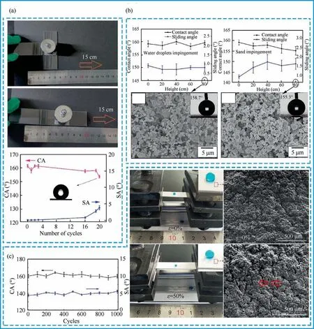
Fig.1 (a)Friction photo of sandpaper and hydrophobicity after abrasion; 60(b)Change of hydrophobicity with drop height and surface morphology in water impact and sand abrasion test; 61 (c) Photographs, surface morphology and contact angle changes of polydimethylsiloxane (PDMS) /SiO2 porous films during stretching.63
In addition, due to the excellent liquid storage inside the porous surface, injecting a smooth lubricant into the porous surface to prepare a hydrophobic coating can save the preparation cost, which has received extensive attention from researchers.64,65The hydrophobic coating acts as a lubricant between the ice and the surface of the aircraft to inhibit ice formation on the surface of the aircraft.Yin et al.66obtained a self-lubricating photothermal coating with anti-icing and de-icing function by infiltrating a smooth liquid into the porous surface to obtain a durable lubricating effect, and using the photothermal effect provided by Fe3O4nanoparticles.However, because the lubricant is depleted by evaporation or consumption, the lifespan of the porous hydrophobic coating infused with the lubricant is short.To improve durability,Wang et al.67reported a solid organic gel material with renewable sacrificial alkane surface layer, which has excellent durability and still maintains good anti-icing and de-icing performance after 20 anti-icing and de-icing cycles or sandpaper wear.
The hydrophobic surface mentioned above can significantly reduce the adhesion of ice to achieve the purpose of anti-icing and de-icing.However,some scholars have found that the factors affecting icing adhesion include not only external environmental factors, but also internal factors such as the properties of icing carriers and their surface roughness.And different conclusions were obtained by studying the physical principles of ice-phobia on hydrophobic surfaces and the relationship between ice-phobia and ice adhesion.Varanasi et al.68studied the effect of frosting on the ice-phobic properties of hydrophobic surfaces, and concluded that the formation of frost on hydrophobic surfaces can increase the adhesion of ice, and frost condensation can occur in all areas of the hydrophobic surface texture, making its hydrophobic properties loss,thereby affecting the effectiveness of the hydrophobic surface in reducing ice adhesion.And Varanasi’s point of view has also been supported by other research groups.69Liu et al.70studied the effect of frosting process on the ice adhesion strength on the surface of micro-nanostructure formed by femtosecond laser.The results show that the ice adhesion strength of micronanostructure surface will be seriously affected by the accumulation of frost on the surface.
The PAD system restrains icing by using chemical or physical properties, which does not require additional energy consumption during anti-icing and de-icing, and the water droplets on the aircraft surface with hydrophobic materials are very easy to roll off under the action of external forces.Thus, the water flow before freezing is greatly reduced and the formation of icing on the aircraft surface is restrained.However, when there is accumulation of frost on the surface of the hydrophobic coating,the adhesion of ice will be greatly increased,resulting in a serious decline in the anti-icing performance of the hydrophobic coating.In addition, the PAD system is mostly in the experimental research stage, and has not been applied in aircraft, and the hydrophobic coating will be damaged by the collision of some particles when the aircraft is moving at high speed, which will seriously affect its antiicing and de-icing performance.
2.3.CAD system
Hydrophobic material is an ideal anti-icing technology because of its low energy consumption.Although various hydrophobic materials have been developed,none of the coatings have been proven suitable for aerospace applications.71In the process of passive anti-icing using hydrophobic materials, the CAD system is combined with electric heating and external light energy to improve the surface temperature of the substrate, so as to achieve excellent anti-icing and de-icing performance.Morita et al.72proposed a hybrid anti-icing and de-icing system combining hydrophobic coating and electrical heating, which was validated and demonstrated in an icing wind tunnel using an icing wind tunnel.The experimental results show that, compared with the existing thermal anti-icing and de-icing system,the combination of thermal method and hydrophobic coating uses only 30%–70%of the power consumption of the thermal method itself, which significantly reduces the power consumption.Pommier-Budinger et al.73proposed a simple-structured analytical model for evaluating the power and voltage required to obtain ice accretion separation at the ice interface.In addition, the team studied the effect of combining different hydrophobic coatings with a low-frequency piezoelectric deicing system, and experimentally measured the ice adhesion of different hydrophobic coatings.The experimental results show that for a given shear stress, a high resonant frequency can reduce the tensile stress entering the PZT material and improve the de-icing efficiency of the system.
Compared with AAD system and PAD system, CAD system has the advantages of green, high efficiency and strong response.However, the key parameters affecting the comprehensive properties of the CAD system and the practical application of the coating need to be further studied.
3.Technical evaluation of aircraft anti-icing and de-icing system
From the previous section,we have learned about three strategies for building an aircraft icing protection system.This section will provide a more detailed breakdown of aircraft icing protection systems and group them into specific technologies or methods.Several typical aircraft anti-icing methods are summarized, such as electric pulse de-icing, electrothermal anti-icing and de-icing, hydrophobic material anti-icing and electro-thermal hydrophobic material anti-icing and de-icing.
3.1.Electrical pulse de-icing
The electric pulse de-icing technology originated from the design of the electric pulse system published by Dr.Levin.74The basic principle is to use the capacitor bank to discharge to the coil to generate a strong magnetic field from the coil and a mechanical force with high amplitude and short duration on the aircraft skin to make the ice break and fall off.Electric pulse de-icing has great advantages.On the one hand,it reduces the energy required for de-icing,and has no obvious negative effect on the parameters of the engine.On the other hand,it expands the air temperature range for de-icing, which can reach -50 °C.and the system is also easily ground tested.The successful application of Dr.Levin in aircraft has set off an upsurge in the research of electric pulse de-icing technology.
In subsequent studies,more scholars optimized the de-icing efficiency of the system based on theoretical algorithms and finite element software analysis.Zhang et al.75proposed an improved de-icing criterion, emphasizing the de-icing effect of shear stress, and used an explicit central difference algorithm to model the electrical impulse de-icing process of the leading-edge structure.The external circuit generates pulses of different sizes under the action of the instantaneous pulse force F on the cross section of the pulse coil, and finally tests the relationship between force and time (Fig.2(a)).Jiang and Wang50used Solidworks software to model the pulse coilaluminum plate, and then imported it into the finite element analysis software (Fig.2(b)).Then the electric pulse de-icing system of the side double coil (Fig.2(c)) and the head single coil (Fig.2(d)) were simulated respectively.The experimental results show that the electric pulse de-icing system with side double coils can greatly improve the de-icing effect of the electric pulse de-icing system and the safety and durability of the leading-edge structure.A simplified model of the leadingedge structure that ignores all rivets is used for modeling(Fig.2(e)).Based on this method, when the required time is 100 μs, the pulse force reaches the peak pressure to achieve the maximum de-icing efficiency.
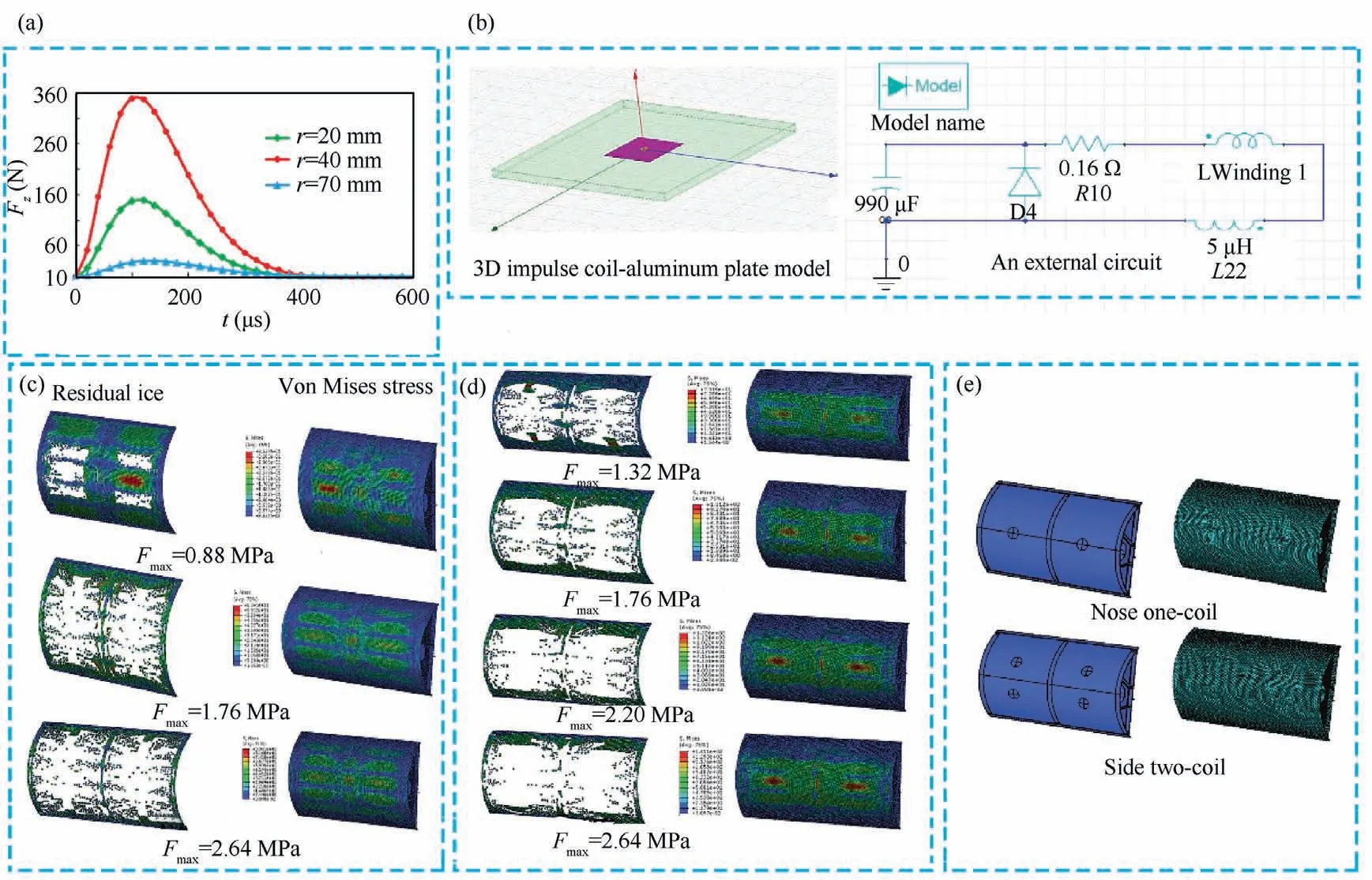
Fig.2 (a)Simplified model of leading-edge structure; 75(b)Electric simulation model; 50(c)Simulation results of side dual-coil electrical pulse de-icing system with simplified model; 75 (d) Simplified model and simulation results of single-coil electric pulse de-icing system of machine head; 75 (e) Relationship between impact force and time.50
Compared with the research that emphasizes theoretical algorithms and finite element analysis under specific models,researchers prefer to simulate the real icing environment to intuitively describe the de-icing process of the electrical pulse system.Wang and Jiang76used circuit parameters such as voltage,inductance,and capacitance obtained by optimization calculations to construct an electrical pulse de-icing system at a natural icing station(Fig.3(a)).Under the condition of voltage U0=500 V and charging capacitor C=1000 μF,the de-icing results are observed and recorded after each pulse (Fig.3(a)).Endres et al.77applied short, high-current pulses to coils placed under the aluminum skin of the leading edge of the wing, causing the pulses to generate opposing time-varying magnetic fields around the coils and the shell.The resulting magnetic forces repel each other, causing the aluminum skin to oscillate for de-icing.In addition,the team tested the electrical pulse de-icing system at -10 °C and -20 °C respectively.The experimental results show that the ice layer on the leading edge of the wing falls off obviously after the electric pulse system is started(Fig.3(b)).Sommerwerk et al.78placed two coils powered by a pulse generator in an aluminum shell leadingedge deicer,and the coils deformed the shell by inducing magnetic force to cause the ice layer to fall off.In addition,the deicing process was recorded in detail by a high-speed camera(Fig.3(c)).The de-icing results show that the electric pulse de-icing system has good de-icing performance.Tian et al.79adopted the dielectric barrier discharge plasma drive technology, installed two kinds of plasma brakes around the leading edge of the model, and adjusted the geometry of the medium in the actuator to reduce the influence of the model shape on the experimental results (Fig.3 (d)).The experimental results show that the power consumption of the de-icing device during the de-icing process is lower than that of the existing de-icing methods and it is a promising de-icing technology.Sommerwerk et al.80carried out the de-icing experiment of the electric pulse system in the icing wind tunnel.With the increase of the number of pulses, the residual ice on the wing gradually decreased, until after the seventh pulse, 5% of the initial icing area was left on the wing(Fig.3 (e)), showing a good de-icing effect.
At present, electric pulse de-icing is mainly researched on circuit analysis model and pulse coil design.Although the finite element analysis method can basically simulate the electric pulse de-icing process, it still needs a refined analysis model and magnetic induction intensity test experiments to simulate the de-icing process more accurately.Besides, in the context of today’s big data era, more of those who focus on the research on electrical pulse de-icing technology still need to do basic research work.In addition, how to combine intelligent algorithms to develop an intelligent-response electrical pulse de-icing system,so that the key technologies of electrical pulse de-icing can be innovated, is the primary problem that scholars need to face in the future.
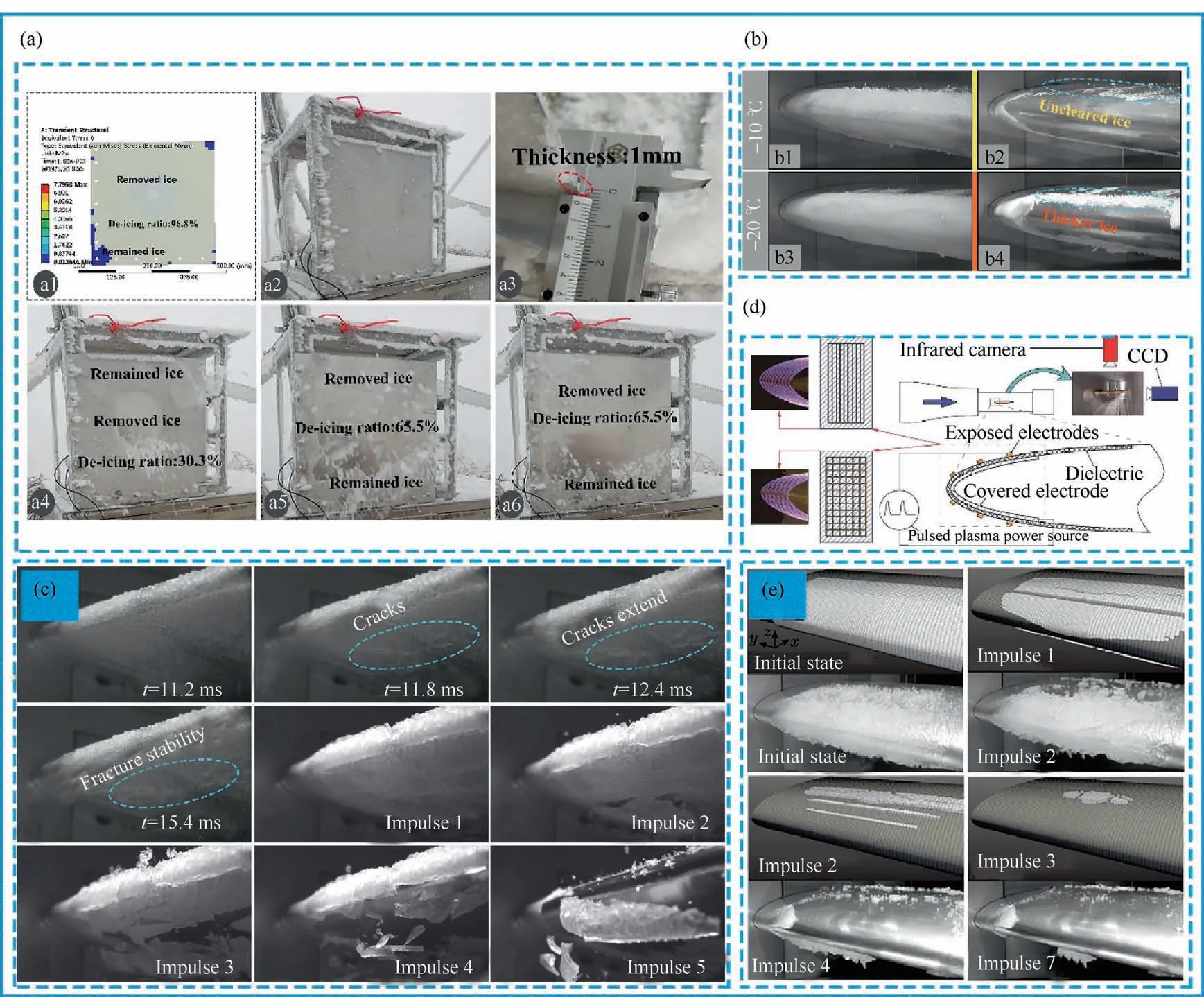
Fig.3 (a)Comparison of prediction results and icing test of natural ice station; 76(b)Ice removal after 8 minutes of icing at-10°C and-20°C; 77(c)Different de-icing process under the number of pulses; 78(d)Schematic diagram of experimental system; 79(e)Comparison of numerical and experimental de-icing results of continuous pulses.80
3.2.Low-frequency voltage de-icing
Low-frequency piezoelectric de-icing systems utilize the principle of inverse piezoelectricity to install piezoelectric drivers where de-icing protection is required on the aircraft.By applying an electric field to the surface of the piezoelectric material,the relative displacement of the positive and negative charges inside the material is caused,which makes the material deform and achieves the purpose of removing the ice layer.With the development of piezoelectric technology,low-frequency piezoelectric de-icing has attracted more and more attention because of its low power loss, and micro-nano vibration does not change the airfoil(compared to pneumatic de-icing)and many other advantages.
The researchers determined the optimal positions of the corresponding device components by means of a combination of finite element theory and experiments, combined with the relevant calculation formula of the shear stress when the ice layer fell off, greatly improving the de-icing efficiency of the de-icing system and reducing the power consumption during the research process.Villeneuve et al.81used finite element software and a numerical model of the blade to analyze the positioning and dimensions of the actuator array (Fig.4(a)),and to simulate the drive excitation resonant frequency and corresponding vibration mode to determine the optimal frequency model.The team then validated the model’s numerical predictions (Fig.4(e)) with a laser vibrometer by locating the actuator in the appropriate location (Fig.4(c)).Based on this method,the arrangement of the driver is optimized,the power required by the low-frequency piezoelectric de-icing system is reduced, and the de-icing efficiency is improved.Bai et al.82deduced a shear model for the bonding between the ice layer and the substructure, then calculated the shear stress at the interface of the ice plate using the finite element method, and compared the shear model and the shear stress obtained by the finite element method (Fig.4(f)).Based on this method,the low-frequency piezoelectric de-icing system is obtained in the process of vibration de-icing, and the initial peeling of ice occurs at the edge.In addition, the team carried out experimental verification (Fig.4(d)), and the experimental results show that although there is a certain error with the finite element simulation results (Fig.4(b)), the overall agreement is good.Volat et al.83developed a finite element numerical model suitable for the new blade geometry and selected frequencies from 0 kHz to 5 kHz for modal analysis.The team then designed a piezoelectric de-icing system applied to a small rotating blade.After the test, the blade achieved de-icing, and the power consumption was reduced by 25% compared with the electric heating system.Pommier-Budinger et al.84proposed a method for calculating the voltage and current of the piezoelectric de-icing system by estimating the voltage,current and power of ice stripping.Based on this method, two actuators and a sensor were placed on the leading-edge structure and then tested in an ice wind tunnel.The correctness of the numerical calculation results is verified by comparing the numerical calculation results with the experimental results.Zhu and Li85carried out modal analysis and simple harmonic analysis through finite element software, calculated the shear stress and mode shape of the experimental surface model,and theoretically proved the feasibility of piezoelectric deicing.Then, piezoelectric de-icing experiments were carried out in a refrigerator at -15 °C, and finally the successful deicing was achieved at a voltage of 650 V and a frequency of 1530 Hz.
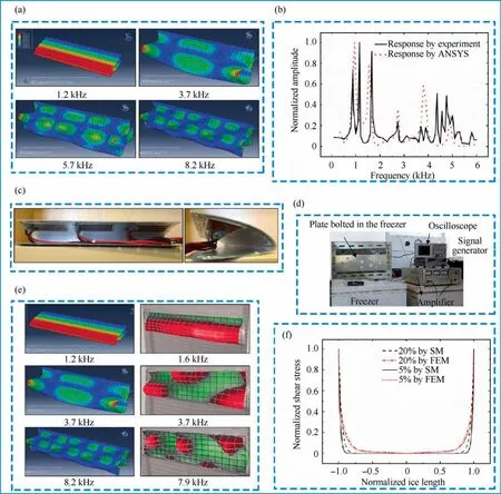
Fig.4 (a) Finite element analysis of resonance modes of Bell206 wing leading-edge structure; 81 (b) Structural response calculated by experimental measurements and harmonic analysis; 82(c)Positional distribution of actuator inside leading edge; 81(d)Schematic diagram of experimental setup; 82(e)Numerical(left)and experimental model(right)comparison example; 81(f)Calculation of shear stress at the interface of ice plate by shear model and finite element method.82
Compared with the combination of theory and experiment,the size and structure design,placement design,applied voltage and frequency of the piezoelectric actuator,and the bonding of the actuator also have a great influence on the improvement of the de-icing effect.Song et al.86arranged 49 piezoelectric plates and 16 piezoelectric plates uniformly on the bottom surface of the substrate respectively, and carried out experiments with different freezing positions and sizes.Fig.5(b)and Fig.5(c) show the active mode control results of 49 piezoelectric sheets on square and rectangular ice cubes.In addition, the team conducted 16 active mode control experiments of piezoelectric materials (Fig.5(a)).It can be seen that although the effect can make the real vibration mode close to the hypothetical de-icing mode, the control effect is not as good as that of 49 piezoelectric sheets.The above simulation results show that the number and placement of the piezoelectric sheets greatly affect the de-icing efficiency, and the place without ice hardly vibrates,making the structure of the piezoelectric de-icing system more stable.Shi and Jia87simulated the different vibration modes of the composite rectangular sample in the finite element method(Fig.5(e)).It can be seen that when the third mode of excitation is applied, the torsional shear stress can achieve better de-icing effect.Moreover, the team performed finite element mode shape simulations of higher-order modes,and along the length of the composite plate, multiple shear stress peaks were observed(Fig.5(d)).The experimental results show that better de-icing effect can be induced under smaller excitation amplitude, which lays a foundation for low-power de-icing and light de-icing of aircraft in flight in the future.Venna et al.88–91provided a method to use a single piezoelectric element to excite shear stress and impact force for de-icing,and studied the excitation effect of different sizes of piezoelectric elements on the leading-edge structure of the wing.And through modeling and finite element analysis, the optimal placement of piezoelectric elements and the structural vibration effect under the optimal applied voltage are studied.
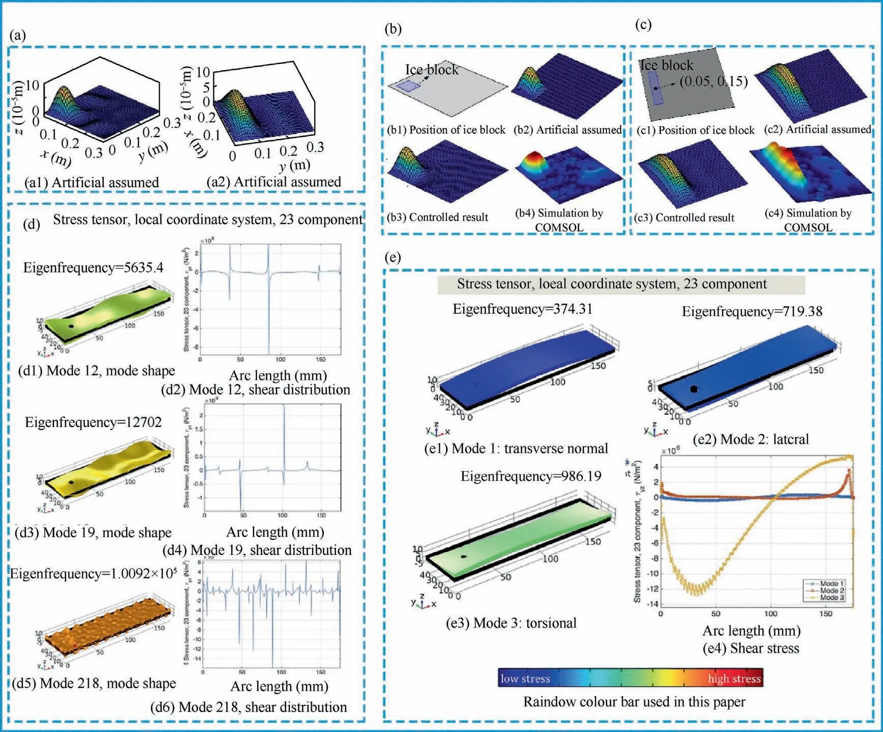
Fig.5 (a)Active mode control results under 16 piezoelectric patches; 86(b)Active mode control results of non-fixed square ice cubes; 86(c)Active mode control results of non-fixed rectangular ice cubes; 86(d)Shear stress simulation of piezoelectric actuators with higher order modes; 87 (e) Shear stress simulation of piezoelectric actuators with different shear stresses in different modes.87
The low-frequency piezoelectric de-icing system has the advantages of simple structure, low noise and good maintainability.It meets the high requirements of modern aircraft for low energy consumption, light weight and no pollution, and has a good development prospect.However, there are still some deficiencies.Due to the limitations of the experimental conditions, the low-frequency piezoelectric de-icing system has only been tested in a cold environment on the ground.There is a big gap between the influence of airflow and the actual flight environment.In the future, scholars need to find a suitable ice wind tunnel or a natural environment with a relatively cold climate to achieve a more realistic experimental effect.
3.3.Ultrasonic de-icing
Ultrasonic de-icing technology uses the thermal effect and mechanical effect of ultrasonic waves to remove ice.The thermal effect of ultrasonic de-icing is due to the fact that in the process of wave propagation,the sound energy of the medium will be converted into thermal energy.On the other hand,when the mechanical vibration of the tool head hits the ice,a large amount of mechanical energy is converted into thermal energy, resulting in the melting of the ice.The mechanical effect of ultrasonic waves is that the mechanical vibration of ultrasonic waves causes the vibration of related particles.When the vibration exceeds a certain limit, the purpose of destroying the ice layer can be achieved.
In the application of ultrasonic waves, by calculating and analyzing the mode shape and natural frequency of the elastic solid, it is ensured that the vibration system works at the resonant frequency and achieves the best power conversion.Through the numerical calculation of finite element,the system is divided into enough suitable units to obtain the optimal frequency of the ultrasonic de-icing system.Wang et al.92carried out icing and de-icing tests in a refrigerator at 15 °C by fixing the side of the aluminum substrate (Fig.6 (a)) using a fixture and adhering two PZT transducers to the aluminum plate through epoxy resin (Fig.6 (c)).The experimental results of ultrasonic de-icing show that ultrasonic de-icing is a continuous process (Fig.6(b)), and the system achieves the best deicing effect when the frequency is 34 kHz, which is consistent with the optimal frequency of 37.5 kHz predicted by the model.Zeng and Song93studied the numerical simulation and experimental test of the sandwich transducer ultrasonic de-icing system.The team used a special adhesive to stick the sandwich transducer on a thin aluminum plate (Fig.6(e)), by placing the aluminum plate in a freezer at -16 °C for up to 44 min, until the surface of the thin aluminum plate was iced up to 2 mm thick layer, followed by ultrasonic deicing experiments(Fig.6(d)).The results of the de-icing experiments showed that the two sandwich transducers removed a 2 mm thick layer of ice from the surface of the thin aluminum plate in less than one minute.
In order to verify the feasibility of ultrasonic de-icing technology on aircraft wings,Yin et al.94connected the transducer made of PZT-4 to an arbitrary waveform generator through an amplifier.Subsequently, the input signal was amplified to the ultrasonic transducer with an amplifier, and after applying a voltage of 50 V, the de-icing experiment was performed in a refrigerator at -15 °C.The experimental results show (Fig.7(a))that the higher the frequency,the better the de-icing effect.In addition, the ultrasonic de-icing time is much shorter than the freezing time.When the ultrasonic de-icing system works continuously under icing weather conditions, the surface of the aircraft wing will always remain ice-free.Wang et al.95used two piezoelectric actuators with a natural frequency of 40 kHz for de-icing research.The de-icing experimental setup is shown in Fig.7(c).A video camera was used to record the ice fragmentation process by placing the deiced specimen and ultrasonic transducer in a freezer at -15 °C for 2 h, and then clamping the composite sheet.The results of the ultrasonic deicing experiment show that the de-icing effect is the most obvious when the ultrasonic frequency is 34.8 kHz, and the main body of the ice layer falls off within 3 min and 6 s.Daniliuk et al.96froze the plate specimen attached with the sensor at-15 °C for one hour, then applied high-frequency alternating current to the transducer using an ultrasonic generator with a maximum output power of 440 W and an output frequency continuously adjusted from 20 kHz to 150 kHz, and finally used a camera to capture the de-icing process (Fig.7 (b)).The experimental results show that the simulation results are consistent with the experimental results, which proves the feasibility of ultrasonic de-icing.
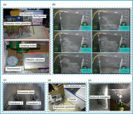
Fig.6 (a) Experimental setup for ice detachment; 92 (b) De-icing process of ultrasonic de-icing system; 92 (c) Fixed position of PZT transducer on aluminum plate; 92 (d) Ultrasonic wave wiring diagram of de-icing experiment; 93 (e) Way of pasting two sandwich transducers on thin aluminum plate.93
Because lithium niobate has strong piezoelectric effect and weak adhesion with ice matrix,using lithium niobate as piezoelectric energy exchange material can greatly improve the efficiency of de-icing and reduce power consumption.The ultrasonic de-icing technology can be better applied to aircraft wings and has a good application prospect.Wang et al.97designed a lithium niobate transducer for ultrasonic de-icing of aircraft wings (Fig.7(d)).In addition, the team studied the relationship between de-icing thickness and time at different ultrasonic frequencies under the experimental conditions of-15 °C and 50 V sinusoidal voltage.The experimental results show that when the frequency is increased to 140 kHz,a single transducer can remove the ice layer with a thickness of 3 mm and an area of 260 mm2in 151 s,which proves the feasibility of the lithium niobate transducer to remove the ice layer on the surface of the wing.In the follow-up study,Wang et al.98used lead-free lithium niobate compounds to fabricate light-weight ultrasonic transducers.In addition, a single transducer was used for shear de-icing and pulse de-icing, and 441.2 kHz was given as the best de-icing frequency.
At present, reducing the output frequency of the system is an important design parameter for designing an ultrasonic de-icing system.Further research is needed on how future workers can perform grid analysis on the structures in the ultrasonic system,and how to ensure that the ultrasonic generator maintains a stable frequency during operation and better matches the impedance of the transducer.
3.4.Pneumatic de-icing
Pneumatic de-icing system is the earliest mechanical de-icing system applied to aircraft.Its working principle is to install a layer of aerodynamic cover composed of expansion tubes on the surface of the wings.When de-icing is required,the system flushes into the expansion tubes.Compressed air is injected to make it expand, and a shear force is applied to the ice layer covering the aerodynamic cover to break the ice layer, and the ice layer gradually separates from the surface of the aircraft under the action of the airflow.In addition to the expansion tube, the pressure regulating source and the vacuum source are also important modules of the pneumatic de-icing system.The pressure regulating source controls the amount of compressed air entering, thereby controlling the expansion degree of the expansion tube to cope with ice layers of different thicknesses.The function of the vacuum source is to control the effective contraction of the expansion tube, to ensure that the surface of the expansion tube is smooth without freezing,and to affect the aerodynamic characteristics of the aircraft as little as possible.
There are two main ways to install the expansion tube in the aerodynamic hood, one is along the span direction, and the other is along the chord direction.Although the resistance of the chordwise arrangement of the conduit is lower than that of the spanwise arrangement of the conduit,the manufacturing difficulty will be increased.At the same time,the installation of the aerodynamic cover on the wing will change the shape of the wing,which will seriously affect the aerodynamic characteristics of the aircraft during flight.Bowden99carried out aerodynamic de-icing experiments on the airfoil of NACA0011, and tested the effects of pneumatic de-icing arrangement along the span direction and chord direction on lift, drag and pitching moment.The results show that when arranged along the spreading direction, the resistance of the pneumatic cover increases from 7%to 37%,and the angle of attack increases from 0°to 4.6°.Broeren et al.100studied the effect of increased icing on the aerodynamic performance caused by the cyclic operation of the aircraft aerodynamic de-icing system by conducting icing wind tunnel experiments on the NACA3012 airfoil.The experimental results show that the interstitial ice accumulation during the cycle can lead to a significant decrease in the aerodynamic performance of the aircraft,and the maximum lift coefficient is reduced by 60%.Palacios et al.19proposed a novel aerodynamic method for protecting helicopter rotor blades from ice accretion by installing six aerodynamic diaphragms below the leading edge of a titanium alloy.When the thickness of the ice accumulation reaches a critical value,the diaphragm begins to expand, causing the leading edge of the wing to deform,which promotes the shedding of the ice layer.
In the pneumatic de-icing system,the life problem is always a difficult point of the pneumatic de-icing system.Since the moisture in the compressed air source will accumulate in the pneumatic hood, it will have a serious impact on the performance of the hose.Goodrich has done research on this situation, designed a pneumatic de-icing system with an exhaust valve, and applied for a patent in the United States and Europe101.The connected path facilitates the discharge of moisture in the compressed air, which greatly increases the reliability and service life of the pneumatic de-icing system.The main components of the pneumatic de-icing system are the input port and the drain valve, which are mutual.
Pneumatic de-icing system has the advantages of light weight and less modification to the aircraft, but when the pneumatic de-icing system works, it will destroy the aerodynamic shape of the aircraft surface,resulting in increased resistance of the aircraft during flight, and poor applicability to high-speed aircraft.
3.5.Anti-icing of hydrophobic materials
The anti-icing technology of hydrophobic materials utilizes the non-wetting phenomenon of objects in nature to prevent ice.The so-called hydrophobic material refers to the material whose surface contact angle with water is greater than 150°and the rolling angle is less than 10°.102–104Compared with traditional anti-icing technologies that rely on electricity or heat, small aircraft usually cannot meet their operating power consumption.However, the use of hydrophobic materials can delay icing to achieve anti-icing effect without additional energy consumption, and is currently considered to be the most effective solution to the problem of anti-icing and deicing system power consumption.
In the past few years, a great deal of research has been devoted to hydrophobic materials capable of retarding ice formation or reducing the adhesive strength during ice formation.105The chemical composition and roughness of hydrophobic materials are two important factors that determine their surface hydrophobicity.106Therefore, to prepare a surface with superhydrophobic properties, the following two principles should be followed: one is to construct a micro-nano rough structure on the hydrophobic surface,and the other is to modify the rough surface with low surface energy substances.107,108Ren et al.109proposed a simple chemical etching and modification method to produce super hydrophobic metal rubber with lotus-like hierarchical structure on the surface of stainless-steel wire by two-step chemical etching process.At the same time, the team carried out waterproof performance test (Fig.8(a)) and oil–water separation test (Fig.8(b)).The experimental results show that the prepared superhydrophobic metal rubber can keep its surface dry when taken out of water,and the superhydrophobic Metal Rubber (MR)has better oilwater separation performance than the pristine Metal Rubber(MR).Chen et al.110introduced an efficient and practical method for surface modification of silicone rubber with nanofiber laser to make it superhydrophobic.After nanofiber laser treatment, a micro-nano rough structure was formed on the surface of the silicone rubber, and its surface had strong hydrophobic properties (Fig.8(d)).Maghsoudi et al.111used compression molding system to directly copy the surface of silicone rubber with micro-nano-rough structure,and prepared a superhydrophobic surface with a contact angle greater than 160° and a rolling angle less than 5°.
The preparation of hydrophobic materials has a relatively complete process, but due to the instability of the surface microstructure of hydrophobic materials, it is particularly important to study the durability of the surface of hydrophobic coatings.Researchers achieve delayed icing of materials through high temperature112or complex fabrication techniques to improve the durability of hydrophobic materials.Although these techniques can produce controllable micronano rough structures, the preparation time is long and the efficiency is low.Asadollahi et al.113studied an atmospheric pressure plasma jet technique to build a microporous structure by placing an aluminum sample at an extremely short jet-tosubstrate distance for multiple air plasma treatments.Meanwhile, the team conducted multiple icing and de-icing cycle experiments to explore the effects on the chemical composition, surface morphology, and wetting behavior of microporous alumina-based surfaces.Zhu et al.62proposed a hydrophobic coating consisting of polydimethylsiloxane(PDMS) nanoparticles (NPs) and PDMS microparticles(MPs)functional NPs through a combination of thermal treatment and spray treatment(Fig.8(e)).The hydrophobic coating was subsequently subjected to a series of durability experiments such as sand impact test, abrasion test and tape peeling(Fig.8(c)).The experimental results show that the hydrophobic coating has good durability and is expected to be used in aircraft windshield anti-icing to improve cockpit visibility.
The advantage of the hydrophobic material anti-icing technology is that icing is fundamentally avoided,no energy is consumed in the process,and very little additional volume or mass is required.However, since the micro-rough structure on the surface of hydrophobic materials is easily destroyed, the hydrophobic properties of the materials decrease sharply or even fail.Therefore,how to maintain the durability of the material for a long time is the key to the research of this technology.
3.6.Electro-thermal anti-icing and de-icing
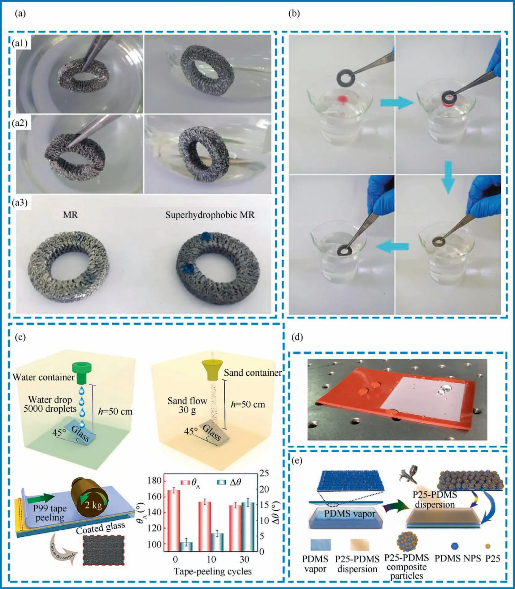
Fig.8 (a) Waterproof performance test;109 (b) Oil-water separation experiment;109 (c) Schematic diagram of preparation process of hydrophobic coating;62(d)State of water droplets on the surface of silicone rubber,unprocessed surface(orange),and superhydrophobic surface (white); 110 (e) Durability test of hydrophobic coating.62
The electro-thermal anti-icing and de-icing system is essentially an electric heater.By converting electrical energy into thermal energy, the heat is transferred to the surface to be protected through the heating element.Through continuous heating,the bottom ice layer melts,which reduces the adhesion between the ice layer and the outer surface of the aircraft,so that the ice layer is removed under the action of centrifugal force or aerodynamic force.
Electro-thermal anti-icing and de-icing technology is one of the traditional aircraft anti-icing and de-icing systems, and a lot of research has been done at home and abroad since the last century.Since the system needs to consume a lot of electricity,the power of the electro-thermal anti-icing and de-icing system largely determines the weight of the aircraft.Due to the limitation of aircraft design standards, the power load should be kept as low as possible.In order to reduce the power of the system, researchers have studied the power characteristics of the electro-thermal anti-icing and de-icing system surface heat transfer mechanism and model optimization.Pourbagian et al.114provided optimization formulas for various constraint problems of the wing electro-thermal anti-icing and de-icing system in the wetting and evaporation states, and conducted numerical optimization simulation of the system by solving the conjugate heat transfer problem between the fluid and solid domains.The optimization results are compared with the experimental data, and the results show that the optimization results significantly reduce the power demand.Targui and Habashi115embedded the simulation results of conjugate heat transfer provided by 3D finite element Navier-Stokes analysis package-ICE code into a special rotor aircraft simulation toolkit.Through reduced-order modeling, the timeliness evaluation of objectives and constraint functions at each iteration is provided.The proposed method optimizes the heating range and power of the heater.Raj and Myong116used partial differential equations to analyze and calculate air flow, droplet collision,ice accumulation and coupled heat transfer,and predicted the anti-icing and de-icing effect of electro-thermal antiicing and de-icing technology.The data are in good agreement,and the minimum power consumption of the aircraft anti-icing and de-icing system is analyzed and calculated based on this method.Wu et al.117used a genetic algorithm to optimize the distribution of heating power on the surface of the component’s electro-thermal anti-icing and de-icing system.Compared with the case where the surface temperature was uniformly distributed, the total heating power was greatly reduced.In addition, the team found that the total heating power was minimal when the water film length was just close to the droplet impact limit.
Compared with model optimization to reduce power to ensure the endurance and safety of the aircraft, the required de-icing threshold heat flux density can be accurately predicted by coupling the internal thermal analysis and calculating the temperature field through simulation.118Bu et al.119established a tightly coupled simulation method for aircraft electrical-thermal anti-icing and de-icing system under icing conditions by using a tightly coupled mass transfer and heat transfer model of backflow water in a virtual thin wall.Considering the influence of the surface temperature distribution on the air convective heat transfer coefficient, the convective heat transfer coefficient under the dry air condition was solved by the tightly coupled simulation method, and compared with the result under the isothermal wall boundary condition(Fig.9(a)).The experimental results show that the tightly coupled simulation method successfully captures the effect of surface temperature on the convective heat transfer coefficient and predicts a higher temperature on the surface of the electrothermal anti-icing and de-icing system at a lower rate of decline.Shu et al.120proposed a numerical method to determine threshold de-icing power density by calculating loosely coupled fluid and temperature fields.In order to provide the necessary ice shape and corresponding validation for the model,the team carried out icing and threshold de-icing experiments on custom-built small wind turbines (Fig.9(c)).The experimental results show that the numerical prediction is in good agreement with the experimental value, and the maximum score error is 9.3%.
The heating element of the traditional electro-thermal antiicing and de-icing system is usually made of metal, which has poor flexibility and is prone to breakage when it is attached to the surface of the wing for a long time.121In addition, the uneven heating of metal components will cause the local temperature to be too high and burn out the internal circuits of the electrical-thermal anti-icing and de-icing system.Due to the advantages of high temperature resistance, shock absorption and fatigue resistance,122composite materials are widely used in the manufacture of aircraft airframes.Yao et al.123fabricated highly aligned carbon nanotube networks by chemical vapor deposition and subsequently inserted them between pre-cured layers of unidirectional carbon fiber reinforced polymer.The electrical conductivity and thermal conductivity were tested under different curing conditions and when carbon nanotube fibers with different layers were sandwiched.The experimental results show that the composite material exhibits good electrical conductivity, and the thermal conductivity does not change significantly due to different conduction modes.Li et al.124fabricated samples using carbon fiber reinforced composites, glass fiber prepregs, and copper meshes, and then embedded sprayable metal films as heating elements in them to prepare composites.The team then tested the effect of thermal cycling and mechanical cycling on the electro-thermal anti-icing and de-icing system, measuring the real-time resistance of the sprayable metal film and the number of cycles to understand the effect of cyclic loading on the heating performance and fatigue life of the system.
Graphene is a perfect two-dimensional material with extremely high electrical conductivity, thermal conductivity and good flexibility, as opposed to adding different media into the polymer matrix.By adding graphene into the polymer,matrix can perfectly solve the defects of low heat transfer efficiency and short life of traditional composite materials.125,126Ba et al.127obtained graphene-polymer composites in surface coating with conductive thin graphene-based polymer matrix.Besides, the team analyzed the thermal mapping of the composite as a function of time and the thermal power density of the composite at different power values (Fig.9(b)).The experimental results show that the as-prepared composites have fast heating response and excellent performance, and can be used as light-duty and low-power electro-thermal anti-icing and de-icing systems.Xiong et al.128prepared graphene-coated carbon fiber/ceramic composites with rapid temperature response through a simple one-step firing method(Fig.9(d)).Based on this method, the team investigated the crystal structure, morphological characteristics, electrical properties, and electro-thermal behavior of modified carbon fibers and carbon fiber/ceramic composites.The experimental results show that the composite material has good electrothermal and mechanical properties.Glover et al.129proved the feasibility of heatable multi-functional graphene surface in de-icing application, and studied the electrical properties,microstructure, heat transfer and electrical response of the material and the shape of the composite structure with the change of temperature.
Over the years, scholars have never stopped research on electrothermal anti-icing technology, but currently only the Boeing 787 is actually applied to its civil aircraft.In the latest civil aircraft Boeing 787,its structural design subverts the previous design ideas.By canceling the engine bleed air system and adopting a multi-electric environmental control system,the stability of the aircraft during the de-icing process is ensured.130In addition, the electric heating anti-icing and de-icing system on the Boeing 787 aircraft adopts heating pads with partition design to prevent the aircraft from icing, and adopts symmetrical logic control on both sides of the aircraft wings to ensure the aerodynamic stability of the aircraft.Even if the wing heating pad on one side of the aircraft fails,the system will automatically power off the symmetrical wings to prevent asymmetrical icing of the wings on both sides due to icing weather conditions, ensuring the flight safety of the aircraft.
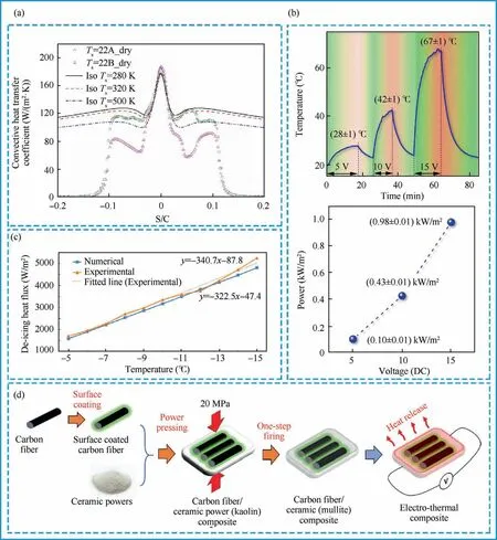
Fig.9 (a)Convective heat transfer coefficients at different surface temperatures; 119(b)Thermal mapping vs time of graphene-polymer composites and thermal power density at different power values; 127(c)Threshold division calculation and experimental results of ice heat flux and ambient temperature; 120 (d) Preparation process of carbon fiber/ceramic composites.128
With the development trend of electric aircraft, various countries have carried out research on the power optimization of electro-thermal anti-icing and de-icing system, which will surely promote the development and rise of the research field of electro-thermal anti-icing and de-icing system.Traditional electro-thermal anti-icing and de-icing systems usually use metal resistance wire as the electric heating element of the ice accretion protection system.Metal heating elements have defects such as heating unevenness and low heating efficiency.New composite materials with electrical conductivity have become one of the research directions of electro-thermal anti-icing and de-icing systems.In the future, an electrothermal anti-icing and de-icing system with low energy consumption and high reliability needs to be designed, and how to make multiple anti-icing and de-icing systems work together for anti-icing and de-icing will still be a huge challenge.
3.7.Hot air anti-icing and de-icing
The hot air anti-icing and de-icing system is a flute-shaped tube in which the heating air is distributed to the leading edge of the anti-icing parts through the air supply pipeline.The fluteshaped pipe heats the leading edge of the skin by means of a small hole impinging jet to achieve the purpose of anti-icing and de-icing.131
In order to accurately control the experimental conditions and reduce the influence of climatic conditions and time, the researchers placed the aircraft model in the wind tunnel to study the interaction between the gas flow and the aircraft model in the hot air anti-icing and de-icing system.Dong et al.132studied a hot air film heating method for a small aero-engine cone anti-icing and de-icing system.In their research work, the team conducted experiments in icing wind tunnels that can simulate the various icing environments that aircraft encounter under actual flight conditions.To maintain the desired hot air flow and velocity,a 10 kW electric air heater is used, the hot air temperature is controlled by a programmable logic controller system with an accuracy of ± 2 °C, and the flow rate is measured using a flowmeter with an accuracy of 1%.The experimental results show that the hot air anti-icing and de-icing system can continuously act on the ice layer on the leading edge of the small aeroengine cone, and the de-icing effect is obvious.
At present, due to the continuous reduction of the cost of computer hardware, the numerical simulation method has a huge economic advantage,so the numerical simulation method has gradually become an important means to study the problem of aircraft hot air anti-icing and de-icing.133–135Yu et al.136used the three-dimensional internal and external robust heat transfer method to calculate and check the performance of the engine nacelle hot air anti-icing and de-icing system.The Euler method was used to calculate the impact characteristics of water droplets,and the inverse distance interpolation method was used to interact with the internal and external flow field data, and the results of the nacelle surface temperature and overflow water were obtained.In addition,the team used the three-dimensional internal and external coupling method to simulate and calculate the outer surface temperature and surface overflow water of the skin under the condition of the total pressure of the hot air vent of the hot gas anti-icing and de-icing system of 211313 Pa and the total temperature of 493 K(Fig.10(a)).The simulation results show that the engine nacelle hot air anti-icing and de-icing system meets the anti-icing and de-icing performance requirements.Saeed et al.22used CFD software to conduct a twodimensional numerical simulation study on the heat transfer of a hot air jet hitting a curved surface like the leading edge of a wing or a wing plate.The team found that the heat transfer efficiency increased by 20% when moving from the flat to the curved model, and the smaller nozzle spacing resulted in better heat transfer at smaller channel heights.In addition,with the increase of the channel inlet position angle, the distance from the jet inlet to the channel increases, and the heat transfer coefficient decreases.The simulation results show that the performance of the hot air anti-icing and de-icing system can be greatly improved by designing the leading-edge surface with reasonable geometry and flow characteristics.Zhang et al.137studied the design and performance calculation of the wing hot air anti-icing and de-icing system, and established a simulation model of the airflow distribution of the hot air anti-icing and de-icing system using the one-dimensional thermal fluid simulation platform Flowmaster.In addition, the team obtained the results of stable surface temperature and return water distribution of the anti-icing and de-icing system through the energy conservation equation (Fig.10(b)).Based on the simulation results of the simulation model, the team verified the performance of the wing hot air anti-icing and de-icing system.The experimental results show that the designed hot air anti-icing and de-icing system can well meet the anti-icing requirements.
The purpose of the hot air anti-icing and de-icing system is to keep the temperature of the aircraft surface above freezing,thereby avoiding icing.It can directly heat the skin with hot air, and has the advantages of simple and reliable structure.However, the hot air anti-icing and de-icing system also has the problems of high energy consumption and poor utilization rate,and the hot air cycle de-icing system is rarely used at present,which easily leads to the formation of ice slips behind the heating area, which seriously affects the flight safety.In addition, there are many simplifications and assumptions of key parameters in the currently used anti-icing and de-icing calculation model, which is quite different from the results of icing wind tunnel experiments or flight experiments.In the future,a more realistic anti-icing and de-icing calculation model needs to be designed,and a lot of research is needed to make technical breakthroughs.
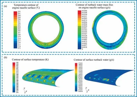
Fig.10 (a)Contour of surface temperature of engine nacelle and contour of surface overflow water flow; 136(b)Experimental simulation results of hot gas anti-icing system.137
3.8.Electro-thermal and hydrophobic material CAD
The traditional electric heating system is prone to breakage when it is attached to the surface of the wing for a long time,which reduces the mechanical strength and makes maintenance difficult.Therefore, directly heating the ice interface is the most effective way to save a lot of energy during heat transfer.But resistance wires and other traditional heating elements are not easy to implement, and the method of CAD by using hydrophobic materials for Joule heating and de-icing is increasingly favored by researchers.
Zhao et al.30prepared a combined electric heating coating based on Multi-Walled Carbon Nanotubes(MWCNTs) and a top superhydrophobic coating on Glass Fiber Reinforced Polymer (GFRP) substrates by spraying method.In order to further investigate the electrical conductivity and anti-icing and de-icing performance of the combined electric heating coating, the electric heating performance test (Fig.11(a)) and de-icing performance test (Fig.11(d)) were carried out.The experimental results show that the combined electric heating coating has strong damage resistance and anti-icing and deicing performance.Fig.11(b) shows the automatic replenishment mechanism of lubricating oil in microchannel.138Fig.11(c)shows the surface preparation of self-lubricating liquid water layer.139Liu et al.140directly constructed closelyarranged micropores on the multi-walled carbon nanotube/polymer-based electric heating coating, and then injected silicone oil into the micropores to obtain synovial fluid injection with good ultra-low ice adhesion Porous Electrically Heated Coating (PEHC) (Fig.11(e)).Then, the power consumption and de-icing efficiency were analyzed through static de-icing experiments and dynamic de-icing experiments.The experimental results show that the porous electric heating coating can significantly shorten the de-icing time, thereby reducing the energy consumption of electric heating by up to 53%.Morita et al.72developed a hybrid anti-icing and de-icing system combining hydrophobic coating and electric heating,and then conducted anti-icing and de-icing tests in a large-scale icing wind tunnel.The experimental results show that the surface covered with the hydrophobic coating reduces the power consumption by 30%to 70%during anti-icing and de-icing experiments.Ibrahim et al.141used 3D printing technology to develop a continuous wire polymer composite heater by combining the continuous wire network with the polymer matrix,and sprayed a hydrophobic coating on its surface to obtain a panel that can be heated with hydrophobic properties.The team then tested the panel in harsh environments to examine the effectiveness of its anti-icing and de-icing system in icing conditions.Experimental results show that the heatable and hydrophobic panel can greatly reduce its power consumption under icing conditions.
The above studies show that the anti-icing and de-icing technology of electrothermal hydrophobic material is the most promising aircraft anti-icing technology.Through the combination of AAD and PAD systems, it makes up for the high energy consumption of electric heating de-icing and the poor anti-icing effect of hydrophobic coating,shortens de-icing time and reduces de-icing energy consumption.However,the actual anti-icing and de-icing performance and damage resistance are the challenges for their large-scale applications.In the future,scholars should focus on the practical significance of CAD of electrothermal hydrophobic materials.
3.9.Other methods
In addition to the above-mentioned common methods, there are some other aircraft anti-icing and de-icing technologies,but most of them are not systematic and have poor comparability or similar inspections for reference,such as plasma antiicing, synthetic jet anti-icing, chemical anti-icing, liquid lubricating layer anti-icing,memory alloy de-icing,etc.This section summarizes these unique methods.
As an active anti-icing technology, plasma anti-icing technology has the advantages of simple structure, fast structure,easy automation and so on.In recent years,as one of the common means of active plasma flow control,dielectric barrier discharge has a wide range of applications in aircraft anti-icing,drag reduction and lift increase.142,143Wei et al.144proposed a nanosecond pulsed SDBD-based‘‘flow-to-plasma hot knife”structure, and tested the de-icing performance of the structure under two typical icing conditions.Excellent anti-icing performance was achieved in both icing conditions.Linder et al.145fabricated a miniaturized dielectric barrier discharge plasma actuator using microelectromechanical systems.And by using a flexible inorganic zirconia substrate to make the actuator sample stretchable, it can be well applied to the aircraft antiicing system.In addition, the icing wind tunnel experiments show that the plasma brake has a good anti-icing effect.
As an active flow control technology, synthetic jet technology has the advantages of simple structure, easy control, and no need for external air source.Nagappan et al.146used the finite element analysis software ANSY-FLUENT and FENSAP-ICE to study the influence of synthetic jet actuator driving on icing with or without jet heating.And the use of heated synthetic jet exciter to achieve the anti-icing effect of aircraft is proposed for the first time.Liu et al.147proposed an impingement rod type plasma synthetic jet for de-icing,and conducted a series of de-icing experiments on it.The experimental results show that compared with the traditional plasma synthetic jet brake, the impact rod type plasma synthetic jet brake has better de-icing performance and can better ensure the flight safety of the aircraft.
The chemical liquid anti-icing technology is to spray antiicing liquid on the surface of the wing to reduce the freezing point of supercooled water droplets and prevent the surface of the wing from freezing.In the early days of the study, the researchers tried to coat the surface of the wing with a layer of salt.When supercooled water droplets were collected on the surface of the wing,the salt dissolved in the water and lowered the freezing point of the water without freezing on the surface.However,salt corrodes the metal skin,so this method has not been applied in practice.The use of anti-icing solution instead of salt can meet the needs of anti-icing.The main components of anti-icing solution are ethylene glycol, propylene glycol and other polyols, which can dissolve the ice and snow on the wing surface and prevent secondary icing.Besides, the anti-icing liquid also contains surfactants and corrosion inhibitors,which can improve the hydrophobicity of aircraft surface,improve the efficiency of de-icing,and prevent aircraft surface corrosion.148
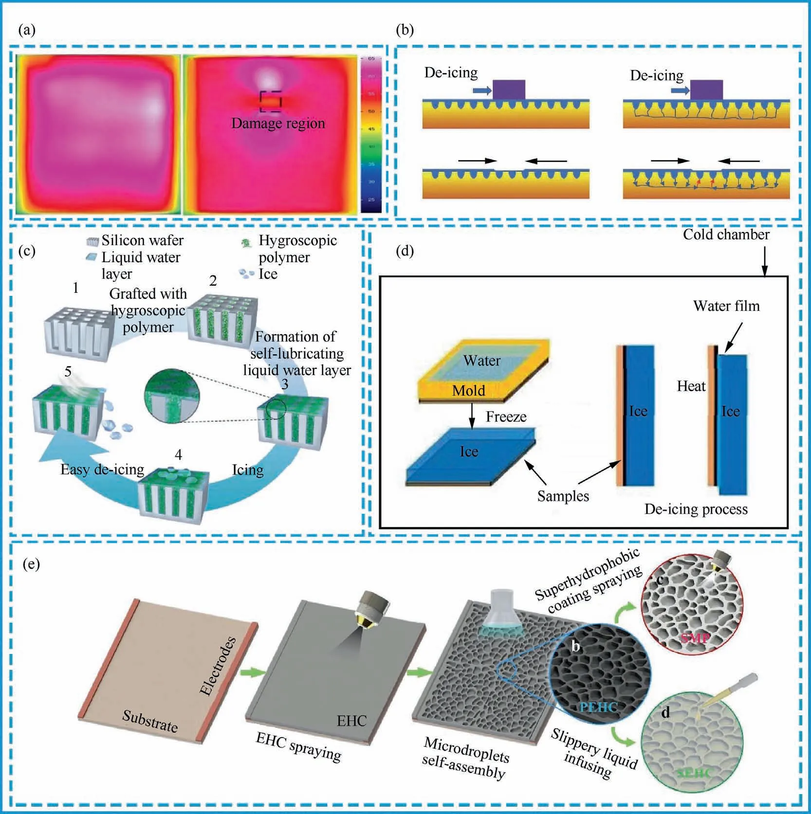
Fig.11 (a) Electric heating performance test before and after coating damage; 30 (b) Schematic diagram of automatic replenishment mechanism of lubricating oil in microchannel; 138(c)Schematic diagram of surface preparation of self-lubricating liquid water layer; 139(d)Schematic diagram of de-icing experiment; 30 (e) Preparation of porous electrothermal coatings with different functions.140
The anti-icing technology of the liquid lubricating layer refers to injecting lubricant into the micro-channels with interweaving.With the help of the natural oil reservoir and container characteristics of the micro-channels, the lubricant is firmly locked and stored in the grid, resulting in an effective hydrophobic performance and achieving delayed icing.Chen et al.139prepared a robust anti-icing coating with a Selflubricating Liquid Water Layer (SLWL) by grafting crosslinked hygroscopic polymers in the micropores of the silicon wafer surface, and when the top of the self-lubricating liquid water layer freezes,the ice will fall off under the action of natural wind (Fig.11(c)).In addition, the surface of the selflubricating liquid water layer also exhibits excellent mechanical durability and self-healing ability.Li et al.138designed a network surface structure with interconnected microchannels and cross-linked nanosheets, and the team performed antiicing and de-icing experiments and stability tests on the structure.In addition, to reduce the influence of the surface lubricating oil layer consumed during the de-icing process on the anti-icing performance of the structure, the team investigated how the lubricating oil stored in the microchannels is automatically replenished (Fig.11(b)).
The memory alloy de-icing method utilizes the unique metallurgical composition of the shape memory alloy,and at a relatively narrow phase transition temperature, the ice surface has a large shape and size change, thereby deforming the ice layer and achieving the effect of removing the ice layer.Liu et al.149studied the de-icing performance of shape memory alloys on non-rotating structures of aircraft and aeroengines,and carried out numerical analysis on the characteristics and influencing factors of shape memory alloy deicers.The advantages of the memory alloy de-icing method are small size,small mass,simple structure,good durability and low cost,but the deformation of memory alloy with temperature changes is difficult to control.The current research work mainly focuses on optimizing the strain of shape memory alloys, increasing the strain output and reducing the temperature hysteresis range.
As mentioned above, scientific researchers have adopted a large number of anti-icing and de-icing technologies such as electrical pulse de-icing, ultrasonic de-icing, anti-icing of hydrophobic materials, pneumatic de-icing and other general methods to remove the ice on the surface of the aircraft, so as to ensure the flight safety of the aircraft in icing climate conditions.In addition, researchers conducted additional tests on the device characteristics of specific technologies,such as durability and impact resistance tests for hydrophobic materials,voltage stability and power loss tests for piezoelectric deicing.However, when researchers conduct aircraft anti-icing and de-icing tests, most of the experimental devices they use are made by themselves, and the experimental test standards are different, and most of them are simulated experiments on computers, which are rarely used on actual aircraft surfaces.This greatly reduces the comparability of the reported test results, which further hinders the practical application of aircraft icing accretion protection systems.In the future,the special equipment for icing tests under special meteorological conditions needs to be further improved.
4.Conclusions and future work
In short,the development of aircraft has brought great convenience to people’s production and life.However, the icing problem of aircraft under special weather conditions seriously threatens the safety of flight.Starting from the hazards of aircraft icing,this paper analyzes the current progress,principles,advantages and disadvantages of typical aircraft anti-icing and de-icing technologies.Although aircraft anti-icing and de-icing technology has been widely used, there are still some shortcomings, and the main conclusions are obtained as follows.
(1) At present, for the construction of aircraft icing protection systems,a variety of aircraft anti-icing and de-icing systems have been developed to achieve the suppression of aircraft surface ice, and the removal of aircraft surface ice.However, in various reports, the test materials used in the aircraft anti-icing and de-icing system are different, the experimental devices are different, and the voltage and frequency used in the de-icing process are not unified and standardized,which reduces the reliability of the anti-icing and de-icing effect.Therefore, the standardization of experimental devices and test materials will be the primary problem faced by aircraft icing protection systems.
(2) Although the electric pulse de-icing technology has obvious advantages such as simple structure, high efficiency and convenient maintenance, the electric pulse de-icing system will cause fatigue damage to the skin, and an electromagnetic field will be generated during the deicing process, and the interference will seriously affect the safety of the aircraft.
(3) The pneumatic de-icing technology has a simple system structure and consumes little air flow, but when the system is de-icing, the expansion tube will protrude from the skin surface of the aircraft, destroying the original aerodynamic shape of the aircraft.
(4) Although the anti-icing technology of hydrophobic materials basically avoids the generation of icing and does not consume energy in the process,the rough structure existing on the surface is very easy to be damaged,resulting in a significant decrease in the hydrophobic performance of the material or even failure,and it is difficult to achieve long-term aircraft anti-icing.
(5) The hot air anti-icing and de-icing technology realizes the direct introduction of a large amount of hightemperature hot gas from the compressor section of the engine, and achieves the advantages of simple and reliable structure, but it consumes a lot of valuable energy and the structural stress problem caused by the temperature gradient of the aircraft surface.Although the electro-thermal anti-icing and de-icing technology has the advantages of high reliability and easy control,the metal heating elements used in it have the defects of poor flexibility, uneven heating and low heating efficiency.
The next research focus of aircraft icing protection system should mainly focus on icing physics,exploring new principles,reducing energy consumption, developing new technologies and applying new materials.In the future, the exploration and application of new principles, new technologies and new materials will improve the efficiency of aircraft icing protection systems and reduce energy consumption.Therefore, it will remain a huge challenge for the aircraft icing protection system to become more environmentally friendly,reliable and efficient in the future.
Declaration of Competing Interest
The authors declare that they have no known competing financial interests or personal relationships that could have appeared to influence the work reported in this paper.
Acknowledgements
This study was co-supported by the Open Fund of Key Laboratory of Power Research of China and the National Natural Science Foundation of China (No.2018YFC0809500), the Sichuan Science and Technology Plan Project, China (No.23NSFSC1923), the Laboratory of Icing and Anti/De-icing of CARDC, China (No.IADL20220406), the Key R&D Special Projects in Henan Province, China (No.221111321000),the Basic Scientific Research Business Expenses of Central Universities, China (No.J2023-033).
 CHINESE JOURNAL OF AERONAUTICS2023年10期
- CHINESE JOURNAL OF AERONAUTICS的其它文章
- Role of unsteady tip leakage flow in acoustic resonance inception of a multistage compressor
- Numerical and experimental investigation of quantitative relationship between secondary flow intensity and inviscid blade force in axial compressors
- Flamelet-like models applied in scramjet combustors: A state of art and prospect
- An improved nonlinear onboard adaptive model for aero-engine performance control
- High-fidelity simulation of blade vortex interaction of helicopter rotor based upon TENO scheme
- Numerical simulation and experimental research on oscillation performance of disc-type jet oscillator