
Geometrically compatible integrated design method for conformal rotor and nacelle of distributed propulsion tilt-wing UAV
2023-11-10 02:16:08ChengHEGngCHENXueSUNShungfeiLIYngLI
CHINESE JOURNAL OF AERONAUTICS 2023年10期
Cheng HE, Gng CHEN, Xue SUN, Shungfei LI, Yng LI
a Unmanned Air Vehicle Research Institute, Nanjing University of Aeronautics and Astronautics, Nanjing 210016, China
b Aerospace System Engineering Shanghai, Shanghai 201108, China
KEYWORDS
Abstract The inner rotors of distributed propulsion tilt-wing Unmanned Aerial Vehicles (UAVs)are often folded in the cruising state and deployed in vertical take-off and landing to cope with the huge difference in thrust requirements.However, the blades of the conventional rotor have poor conformality with the nacelle profile,which will greatly increase the drag of the UAV after folding.This paper proposes an integrated method for the design of rotor and nacelle considering geometric compatibility to reduce the drag of the folded rotor and nacelle, so as to further improve the aerodynamic efficiency in cruise while ensuring the rotor efficiency in the vertical flight mode.A geometric mapping model based on nacelle design parameters and rotor design parameters is established,and a parametric model and aerodynamic optimization model of the outer arc airfoil family are developed.In addition,a rotor performance analysis model and a neural network response surface model for nacelle drag prediction that meet the requirements of confidence level are established.Based on the oblique inflow blade element momentum theory method, numerical simulation method, and genetic algorithm, an integrated optimization framework of the design of the conformal rotor and nacelle is built.Then, a geometrically compatible integrated optimization for the rotor and nacelle is carried out with the objective of maximizing energy efficiency in the full mission profile.Finally,a conformal rotor and nacelle design solution is obtained,which satisfies geometric compatibility and thrust constraints while providing high thrust efficiency and low cruising drag.A comparison of the results of the integrated design and the conventional rotor optimization design shows that the drag of the conventional rotor is 3.45 times that of the conformal integrated design in the cruising state, which proves the effectiveness and necessity of the proposed method.
1.Introduction
The tilt-wing Unmanned Aerial Vehicles (UAV), which can combine the advantages of the multirotor and fixed-wing UAVs in vertical takeoff and landing and efficient cruise, has attracted much attention in the aviation field.As the distributed propulsion technology is intensively studied, this advanced form of propulsion shows the potential to increase the power safety margin and improve the aero-propulsive efficiency.Thus, researchers have tried to apply the distributed propulsion concept to the tilt-wing UAV to form a distributed propulsion tilt-wing UAV such as GL-10 and LightningStrike.1,2
As one of the most important power components,the rotor plays a crucial role in the overall performance of the distributed propulsion tilt-wing UAV.For the tilt-wing configuration, the thrust requirement varies significantly in different flight modes.In vertical flight and transition modes, thrust is required to balance the gravity of the whole aircraft, while in the forward flight mode, thrust is only required to balance the drag of the aircraft.Therefore, the rotors of such aircraft are characterized by complex design conditions and high sensitivity of overall parameters.The application of distributed propulsion systems exacerbates the complexity of constraints in the design process.Moreover, the inside rotors of the distributed propulsion tilt-wing UAV are folded up at cruise to reduce drag and improve cruise efficiency.Although the rotor and its power nacelle are individually optimized, the shape of the rotor blades folded on the outside of the nacelle significantly disrupts the flow field of the nacelle.As a result, the drag of the nacelle increases drastically and the advantages of the optimized design cannot be exploited.Therefore, it is necessary to carry out an integrated design of the rotor and nacelle considering geometric compatibility to reduce the drag of the folded rotor and nacelle, thus further improving the aerodynamic efficiency at cruise while ensuring the efficiency of the rotor in the vertical flight mode.However, there is currently no integrated design method for conformal rotor and nacelle.
At present, research on rotor design involves various aspects such as airfoil design, multi-objective optimization,and multidisciplinary design.Among them, in rotor airfoil design, Wang and Zhao3optimized a rotor airfoil considering multiple design points, which significantly improved the liftdrag and moment characteristics of the rotor.Based on the SC1095 airfoil, Massaro and Benini4carried out the multiobjective optimization design of the rotor airfoil by using the evolutionary algorithm and the surrogate model, and finally obtained the optimal Pareto front.Zhao et al.5used the principal component analysis dimensionality reduction method to transform a six-objective rotor airfoil design problem into a two-objective design problem, and obtained a set of airfoils with significantly improved drag divergence Mach number,moment coefficient, zero-lift drag coefficient, and lift-to-drag ratio.In terms of the overall rotor shape,Chang and Sullivan6used the conjugate gradient method to optimize the twist distribution of propeller blades.Liu et al.7conducted an optimization design of the propeller blades of the V-22 tilt-rotor aircraft with the sequential quadratic programming method,which improved the hovering efficiency of the whole aircraft by 3%.Ku¨mmel and Breitsamter8carried out an integrated aerodynamic/structural optimization of the rotor blade.Capitao Patrao et al.9designed a two-bladed propeller for highspeed flight based on the wake analysis method,and the blade tip vortex strength is reduced and the performance is improved compared with those of conventional rotors.Kovalovs et al.10adopted a rotor blade active twist control method to optimize the rotor blade,which improved the aerodynamic performance of the rotor while effectively reducing rotor noise.Vigevano et al.11investigated both the rotor blade shape and the aerodynamic interference between the rotor and the wing of the Erica tilt-rotor aircraft, and verified the aerodynamic performance improvement by calculations and tests.Alba et al.12proposed a multidisciplinary design optimization framework considering the influence of rotors on the aerodynamic characteristics of the wing.Zhang et al.13used a nested mesh and momentum source approach to simulate the disturbance flow field during the transition of a tilt-rotor aircraft.Then,Droandi et al.14completed the design of the rotor and wing considering the aerodynamic interference between the wing and rotor of a tilt-rotor aircraft in all flight modes.
Summarizing the existing research,it can be found that the current rotor design is no longer only focused on the rotor performance in the design state, but is more closely associated with the mission scenario.The design objectives, constraints,and approaches are more complex and diverse.These design methods for conventional rotors have certain implications for the design of conformal rotors.However, considering the requirement of geometric compatibility between the rotor and nacelle, the rotor geometry parameterization method,the airfoil family optimization method under geometrical compatibility constraints, and the rotor/nacelle integration optimization method with multi-objectives and under multiconstraints are significantly different from traditional design methods.These studies cannot be directly applied to the integrated design for the rotor and nacelle considering geometric compatibility.
This paper proposes a geometrically compatible integrated design approach of conformal rotor and nacelle, so as to further improve the aerodynamic efficiency of the whole aircraft in the cruise state while ensuring the efficiency of the rotor.The method draws on traditional rotor and nacelle design methods, and introduces multiple new functional modules such as the rotor parametric model under geometric compatibility constraints, the outer arc airfoil family optimization model, and the rotor performance analysis module based on the oblique inflow Blade Element Momentum Theory(BEMT)method.With the proposed method, it is possible to comprehensively consider the power requirements of the distributed tilt-wing UAV under different flight modes, and obtain a design solution for the conformal rotor and nacelle that provides high thrust efficiency and low cruising drag.
This paper is organized as follows.In Sections 2 and 3,the shape parameterization method and the aerodynamic analysis model are described.The aerodynamic optimization of the outer arc airfoil family is presented in Section 4.Section 5 describes the description and solution process of the integrated rotor/nacelle optimization problem.The case study and results are then shown in Section 6.Conclusions are given in Section 7.
2.Shape parameterization considering geometric compatibility
The main flight modes of the tilt-wing UAV include the vertical flight mode, transition flight mode, and forward flight mode.Due to the huge difference in the thrust required by the tilt-wing UAV under different flight modes, some rotors are folded in the forward flight mode.The geometric compatibility between the rotor and the nacelle means that rotor blades can completely fit the nacelle profile in the folded state.In the vertical flight and transition modes,rotor blades unfold naturally under centrifugal force,as shown in Fig.1.This geometric compatibility imposes special requirements on the airfoil shape, twist angle, and chord length of each section of the rotor.Therefore, it is necessary to consider the geometric compatibility when building the parametric models of nacelles,rotors, and rotor airfoils.
2.1.Nacelle shape parameterization
Because the nacelle of the distributed propulsion tilt-wing UAV adopts a revolving body configuration, the generatrix determines the shape of the nacelle, so it is only necessary to parameterize the generatrix.The Non-Uniform Rational BSpline(NURBS)method is used to parameterize the generatrix of the nacelle.The method is based on a strict mathematical expression, and is thus geometrically invariant and convexity preserving.15The NURBS curve can be generated based on a series of control points and a node vector, and the specific expressions can be found in Refs.16,17.
The number of control points should be large enough to ensure sufficient fitting accuracy.However, excessive control points may lead to Runge’s phenomenon and distort the curve.Since the nacelle is relatively simple, seven control points can be used to guarantee the fitting accuracy, as shown in Fig.2.Among them, the leading point P1and the trailing point P7are fixed.The x-coordinates of point P2and point P1are consistent to satisfy the tangency of the leading edge of the nacelle.Points P3, P4, and P5have the same y-coordinate.The maximum radius of the nacelle can be changed by adjusting the y-coordinate of these three points.The axial position of the maximum section is controlled by the x-coordinate of point P4.The x-coordinates of P3and P5control the profile trend of the front and rear sections, respectively.Point P6is used to adjust the tail shape of the nacelle.
2.2.Rotor airfoil parameterization
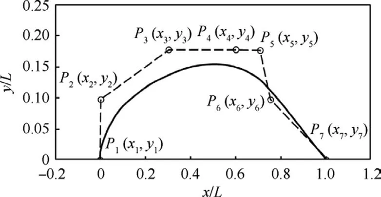
Fig.2 Nacelle shape parameterization method.

Fig.3 Outer arc airfoil parameterization method.
To meet the geometric compatibility between the rotor blade and the nacelle profile in the folded state, the upper surface of the conformal rotor airfoil is defined by the nacelle profile as an arc shape, as shown in Fig.3.Therefore, the airfoil of the conformal rotor is also called the outer arc airfoil.In the process of airfoil parameterization, only the lower airfoil surface and the leading edge need to be parameterized.The parameterization of the lower airfoil surface is performed based on the NURBS curve.As shown in Fig.3, the given outer arc with radius R and central angle ζ is divided into N parts, then the position of the type-valued point Fican be determined from the length of the line segment OaFi(aiR)and the angle between OaFiand OaF0(biζ).According to these type-valued points,nodal displacement vectors are constructed and curve basis functions are generated using the accumulated chord length parameterization method.Then the lower airfoil profile can be fitted.The leading edge of the airfoil is determined based on the three-sided tangent condition of the upper airfoil, the lower airfoil, and the line segment OaF0.
2.3.Rotor shape parameterization
In the conventional rotor parameterization process, the rotor shape is usually described directly using the distribution of the twist angle θ~and chord length c along the radius station~r to facilitate the analysis of rotor performance.Fig.4(a)shows the parameterized form in the unfolded state, that is,the rotor can be represented by the unfolded parameter setHowever, the problem with this parametric form is that geometric compatibility is not guaranteed.To solve this problem,a set of geometric parameterization systems in the folded state is first established to ensure the geometric compatibility between the rotor and the nacelle.Then, the mapping relationship between the folded parameter set ΩFand the unfolded parameter set ΩUFis established according to the invariance of the rotor shape.As shown in Fig.4(b),in the folded state,the rotor can be represented by the folding parameter set ΩF={x,r,θ},where x is the offset,r is the local section radius, and θ is the angular offset.

Fig.4 Rotor shape parameterization method in folded and unfolded state.
2.3.1.Mapping of stations along radius
Fig.5 presents the geometry of a typical rotor/nacelle that satisfies the geometric compatibility in the folded and unfolded states.The nacelle generatrix equation is expressed using the method in Section 2.1, and can be abbreviated as r = f(x).According to the geometric invariance, it is clear that the arc control sectioninthe foldedstate corresponds to thesectionin the unfolded state.Therefore, thepositionalong the radial radius ~riin the unfolded state corresponding to the position of the rotor blade xiin the folded state is
2.3.2.Mapping of twist angle distribution
The twist angle of the rotor in the unfolded state can be decomposed into the relative twist angle and the root chord installation angle.The relative twist angle is constant in the unfolded and folded states.The root chord installation angle is generated by the inertial force during the blade unfolding process.
From the geometric relationship shown in Fig.6, it can be seen that the relative twist angle βiof section ︿AiBirelative to the initial section ︿A0B0in the folded state can be expressed as

Fig.6 Relative twist angle in folded state.
where θiis the angular offset of the section.Therefore, it is only necessary to define the variation of θialong the xdirection to obtain the relative twist angle βi.In this research,a fourth-order Bezier curve is used to represent the angular offset θi, as shown in Eq.(3).
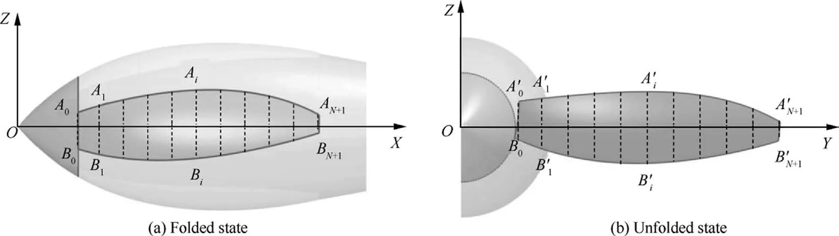
Fig.5 Sections along radius of rotor in folded and unfolded state.
In the actual unfolding process, blades rotate at a specific angle around a specific axis of the root into the unfolded state under the action of inertial forces.However, it is difficult to give the spatial axis and rotation angle directly in the rotor design stage.Therefore, the rotation process is decomposed based on Euler’s Law, as shown in Fig.7.Among them, the rotary motion around the O?Z?axis makes the rotor fully open,and the rotary motion around the O?Y?axis adds the root chord installation angle to the unfolded blade.Then the actual twist angleof the control sectionafter the rotor blade is fully unfolded is
where ψ is the rotational Euler angle of the rotor around the O?Y?axis.
2.3.3.Mapping of chord length distribution
The chord length distribution in the unfolded state of the blade is consistent with that in the folded state,so the chord length ciof each section can be solved in the folded state, namely
where ζiis the central angle of section ︿AiBi.In the design process, the distribution of the circular angle ζ along the xdirection can be expressed with two quadratic curves whose vertices are tangent to each other.When the coordinates of the vertex of the quadratic curve are (xp, yp), the coordinates of the starting point of the first quadratic curve are (0, ys),and the coordinates of the ending point of the second quadratic curve are (1, ye), the distribution of the central angle is
3.Aerodynamic performance analysis model
3.1.Nacelle and airfoil aerodynamic analysis model
3.1.1.Numerical simulation methods
The volume Reynolds number of the nacelle of the tilt-wing UAV is low, so the influence of laminar transition must be considered in the calculation.In this study, the Navier-Stokes equation is used as the main governing equation.The γ-Reθtransition model proposed by Menter and Langtry is used as the turbulent model.This model incorporates the intermittency factor γ and the momentum thickness Reynolds number Reθinto the SST k-ω turbulence model,so as to predict the initial position of transition and simulate the flow in the transition region.18The transport equation for the intermittency factor γ is expressed as follows:
where ρ, Uj, xj, μ, and μtare density, j-directional velocity, jdirectional coordinate,molecular viscosity,and eddy viscosity,respectively.Pγ1and Eγ1are the transition sources,and Pγ2and Eγ2are the destruction and re-laminarization sources.The equation for the local transition Reynolds number ~Reθtis expressed as follows:
where σθtis the diffusion coefficient,and Pθtis the source term.Some previous studies18,19also verified the accuracy and reliability of this method.
3.1.2.Nacelle drag RSM
Although the nacelle drag prediction using the CFD method has high accuracy, the execution speed is slow.The Response Surface Model (RSM) has the characteristics of simple structure and high computational efficiency.It can clearly express the relationship between design variables and response parameters, and thus is widely used for optimization design.Here,the nacelle drag RSM is built with the back propagation neural network algorithm,20and the specific process is shown in Fig.8.
In order to improve the fitting accuracy of the RSM, it is necessary to ensure the comprehensive coverage of the entire design domain by the sample set and avoid local mapping defects caused by the centralized distribution of the samples.The constraint-based Latin hypercube sampling approach21is adopted for sample generation.Compared with the traditional Latin hypercube sampling method, this approach can effectively improve the feasibility of the sample space, as shown in Fig.9.Among the generated samples, 85% of the samples are used to train the neural network RSM, and 15%of the samples are used to test the accuracy of the final trained RSM.Fig.10 presents the fitting accuracy and prediction accuracy of the neural network RSM trained with 1000 samples.
3.2.Rotor aerodynamic analysis model
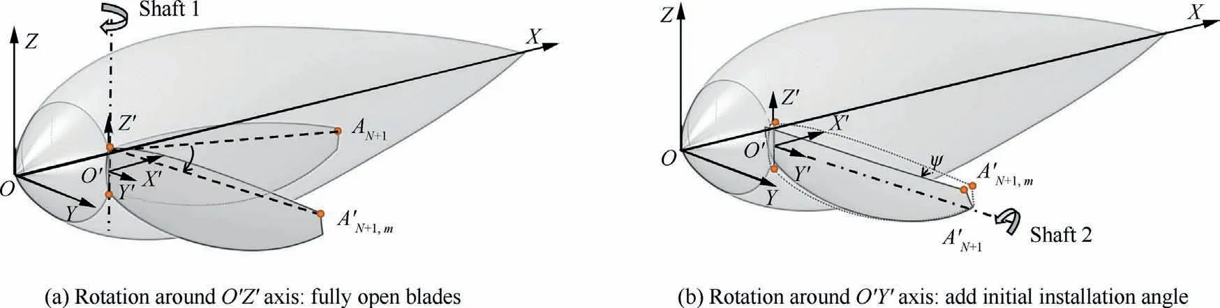
Fig.7 Euler angle decomposition of unfolding process.
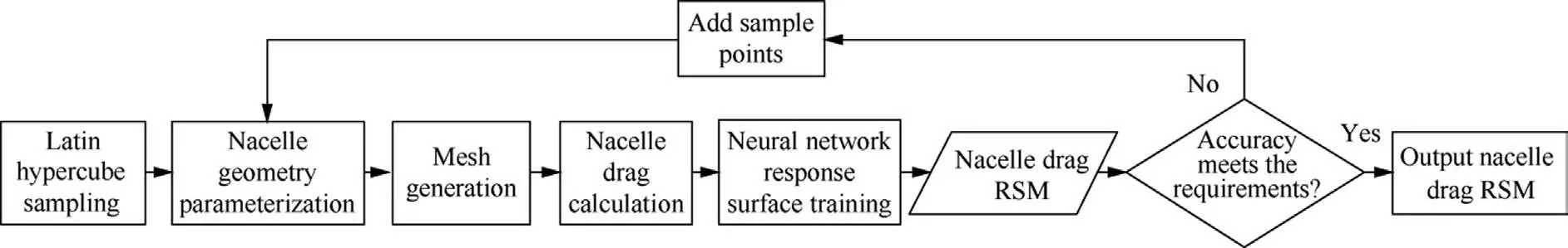
Fig.8 Nacelle drag RSM establishment process.
The thrust,power,and torque of the rotor are calculated based on the Blade Element Momentum Theory (BEMT).This method not only considers the detailed rotor geometry and airfoil aerodynamics, but also describes the slip flow characteristics with high fidelity.Meanwhile, the calculation speed is fast,22which makes the BEMT method one of the most suitable rotor aerodynamic analysis methods for system-level optimization.Due to the specificity of the rotor shape and the complexity of flight conditions, it is still necessary to perform the airfoil pre-calculation and adjust the inflow mode when analyzing the rotor aerodynamics of the tilt-wing UAV with this method.
3.2.1.Airfoil pre-calculation
The prediction accuracy of the BEMT method is closely related to the accuracy of the airfoil aerodynamic input.The airfoil of the conformal rotor is obtained by optimization, as described in Section 4.The airfoil aerodynamics are simulated with the high-confidence CFD method.In addition,the impact of the finite blade span is considered using the method proposed by Jacobs and Anderson,23and the rotating blade stall delay effect is corrected with the method proposed by Elgammi and Sant.24
3.2.2.Oblique inflow BEMT method
In the transition mode,the oblique inflow angle of the rotor is relatively large.The angle of attack and inflow velocity of each blade element change periodically with the rotation of the blade.However, the classical BEMT method adopts the axial uniform inflow assumption when performing blade performance calculations,which may lead to large errors in the presence of an oblique inflow angle.Therefore, it is necessary to correct the axial uniform inflow assumption and form an oblique inflow BEMT method.At any radius station rm,the thrust T, normal force Ft, and torque Q of the blade element are no longer expressed by a single value, but by the time-averaged value of the entire rotation period,25that is,
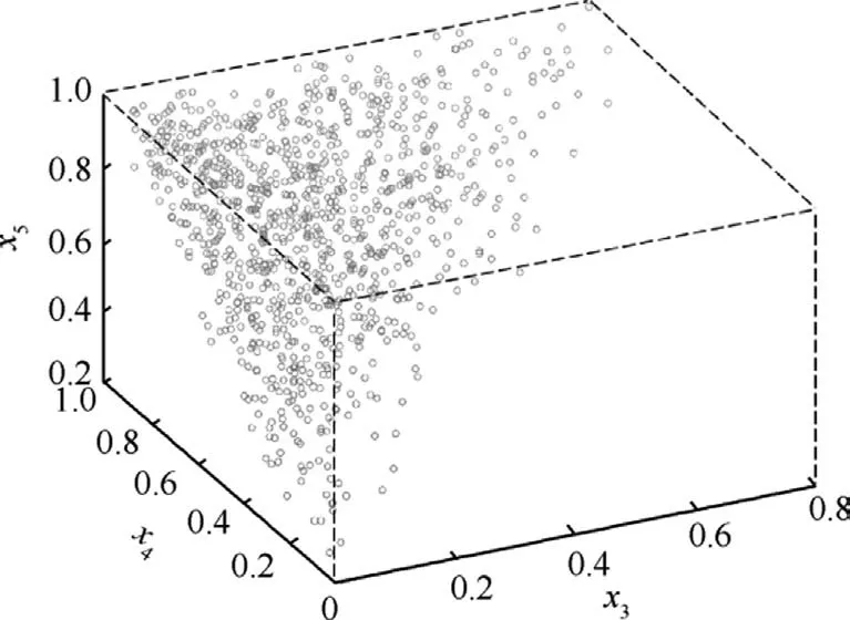
Fig.9 Latin hypercube method with constraints.
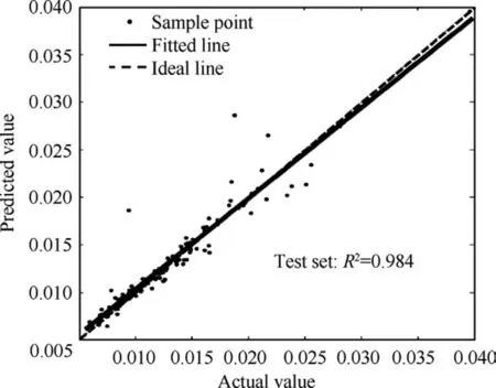
Fig.10 Accuracy of nacelle drag neural network RSM.
where φ is the blade phase angle,Nbthe number of blades,and β the induced angle; Leand Deare the blade element lift and drag with the local inflow velocity, respectively.Meanwhile,based on the Glauert momentum theory,the thrust T and torque Q of the blade element at radius station rmcan be expressed as
where δ is the oblique inflow angle; ˉu0and ˉVt0represent the time-averaged axial and circumferential induced speeds,respectively.Based on Eqs.(9) and (10), the values of ˉu0and ˉVt0can be solved using the Newton iteration method.Then,the time-averaged thrust, normal force, and torque of the blade element can be obtained.Integrating these forces and torque along the radius yields the overall rotor aerodynamics under the oblique inflow condition.
To verify the accuracy of the above oblique inflow BEMT method, the simulation results of the propeller under the oblique inflow condition are compared with the wind tunnel test data provided by McLemore and Cannon.26The variations of thrust coefficient CTand power coefficient CPwith the advanced ratio J are shown in Fig.11.In Fig.11, ζ is outer arc central angle.It can be seen that the errors are negligible at the design operating state of the rotor.Although the error of the proposed method increases when the operating state deviates excessively,the maximum error value is still less than 8%.
4.Aerodynamic optimization of outer arc airfoil family
In conventional rotor design, it is common to perform affine changes to the airfoil at the 70% radius station to generate the overall airfoil family.However, there is no geometric scaling relationship between the outer arc airfoils with different central angles in the conformal rotor design.Therefore, the aerodynamic optimization of the outer arc airfoil with different central angles is carried out separately in this section.The specific optimization process is shown in Fig.12.The objective of the outer arc airfoil optimization is to improve the thrust efficiency factor of the airfoil in the design state as much as possible while satisfying the geometric compatibility and thickness constraints.In addition, the rotor speed and inflow velocity vary with the adjustment of the flight state,which requires robust airfoil design results.Thus, two checkpoints CL1and CL2are set on both sides of the airfoil design lift coefficient CLd.The thrust efficiency factors of the three points are weighted when evaluating the utility of the individual.
To ensure the stiffness of the rotor,the thickness of the airfoil at the feature section needs to be limited.The general blade tip thickness δ1and blade root thickness δ0are larger than 8%and 20%, respectively.Therefore, the outer arc airfoils with the central angles of 20°, 30°, 40°, 50°, and 60° are optimized with the maximum relative thickness δmnot less than 8%,15%,20%,and 25%as constraints.The final outer arc airfoils are shown in Fig.13.The aerodynamic calculations of these optimized outer arc airfoils are completed based on the CFD method, and some of the results are presented in Fig.14.In Fig.14, CL1.5/CDrepresents efficiency factor, ηFis thrust efficiency.
According to the optimized shape of these outer arc airfoils,aerodynamic analysis is performed with a given Reynolds number sequence, and the variations of the aerodynamics of each airfoil with the angle of attack under different Reynolds numbers are obtained.On this basis, the aerodynamic database of the outer arc airfoil family is established by interpolation calculation with the airfoil central angle, the airfoil thickness, the operating Reynolds number, and the angle of attack as the input, and the lift and drag coefficient as the output.The specific generation process is shown in Fig.15.This aerodynamic database is a necessary input for the integrated optimization of the rotor and nacelle.
5.Rotor/nacelle integrated optimization problem description
5.1.Design variables
According to the rotor and nacelle geometry shape parameterization method in Section 2, the design variables involved in rotor/nacelle integrated optimization can be divided into five categories, namely, the nacelle generatrix control parameter ψna, the rotor twist angle control parameter ψnz, the central angle control parameter ψc,the rotor radius control parameter δR, and the number of blades Nb.Among them, the nacelle generatrix control parameter ψnais defined by the NURBS curve control point coordinates, and equals {y2, x3, y3, x4,x5,x6,y6}.The rotor twist angle control parameter ψnzis represented by the rotational Euler angle ψ and the characteristic coefficient sets in the fourth-order Bezier curve, that is, ψnz={ψ, p1, p2, p3, p4}.The central angle control parameter ψcis determined by the coordinates of the control points of the two tangent quadratic curves, namely, ψc={xp, yp, ys, ye}.The rotor radius control parameter δRis defined by the ratio of the blade radius to the nacelle length.Combining the geometric characteristics of the nacelle and the rotor, the ranges for these variables and the constraints to be satisfied between the variables are shown in Table 1.
5.2.Constraints
Constraints that need to be met during the optimization design process include: (A) Motor accommodation constraint: The nacelle radius at the location of the motor rlois required to be larger than the motor size rm, so as to prevent the motor from interfering with the nacelle structure during operation;(B) Blade non-interference constraint: The number of blades and the central angle of each control section should be set to avoid geometric interference between different blades; (C)Blade tip Mach number constraint: The blade tip Mach number Matipdoes not exceed the specified value Ma0in any operating state; (D) Rotor thrust constraint: The rotor static thrust T must meet the requirements of the hovering state;(E) Rotor speed constraint: The rotor speed Nrpmshould be within the given design range to ensure the efficient operation of the motor.These constraints are shown in Table 2.Among them, ξmtis the motor nacelle clearance parameter, whose value is generally taken as 1.05–1.1;T0is the thrust of a single rotor required in the hovering state.

Fig.12 Outer arc airfoil optimization process.
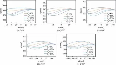
Fig.13 Outer arc airfoil family optimization results.
5.3.Objectives
The nacelle or rotor is usually optimized with the objective of minimizing the nacelle drag DNAor maximizing the hovering thrust efficiency ηF, respectively.However, this design approach cannot account for the geometric correlation between the rotor and the nacelle in the integrated design.Therefore, this paper proposes a design method based on the concept of energy consumption, which does not consider the individual rotor efficiency or nacelle drag but takes reduction of the comprehensive energy consumption introduced by the rotor and nacelle during the entire flight process as the criterion.Then the objective is designed based on this criterion.The energy consumption introduced by the rotor and nacelle can be expressed as
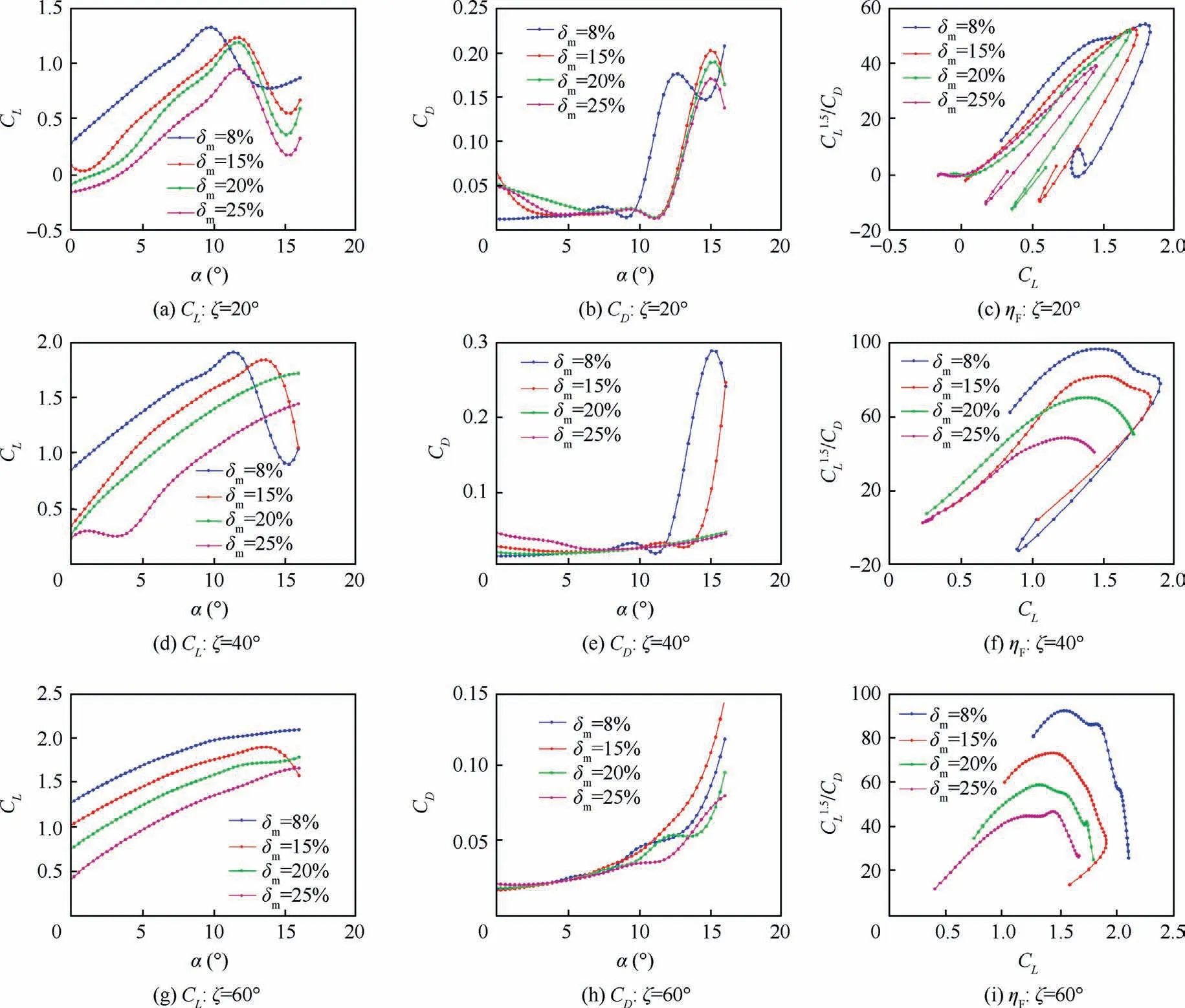
Fig.14 Aerodynamic characteristics of outer arc airfoil family.
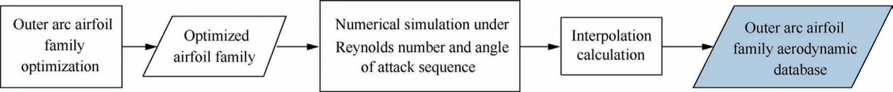
Fig.15 Generation process of aerodynamic database of outer arc airfoil family.
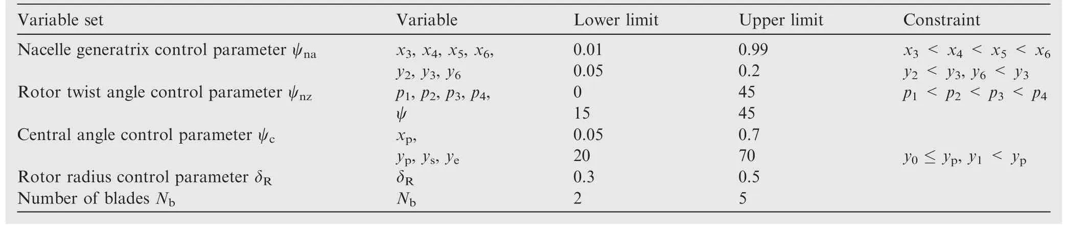
Table 1 Range of design variables.
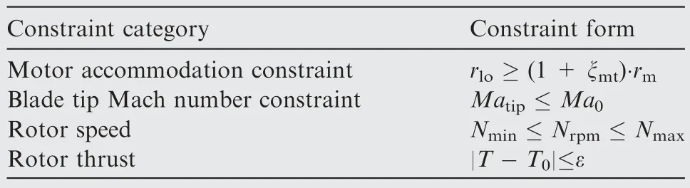
Table 2 Constraints.
where EHand ECare the rotor hovering energy consumption and nacelle cruise energy consumption, respectively; NNAis the number of nacelles;Vcruis the cruise speed;THis the total hovering time; TCis the fixed-wing cruise time.
Finally,the problem of geometrically compatible integrated design for the rotor and nacelle can be summarized as
5.4.Implementation optimization
The implementation process of the geometrically compatible integrated optimization for the rotor and nacelle is shown in Fig.16.This process includes three major parts, namely, the global preprocessing, core utility evaluation, and optimization process control.
The global preprocessing module is used to generate the aerodynamic database of the outer arc airfoil family and establish the nacelle drag neural network RSM, which are detailed in Sections 3 and 4.
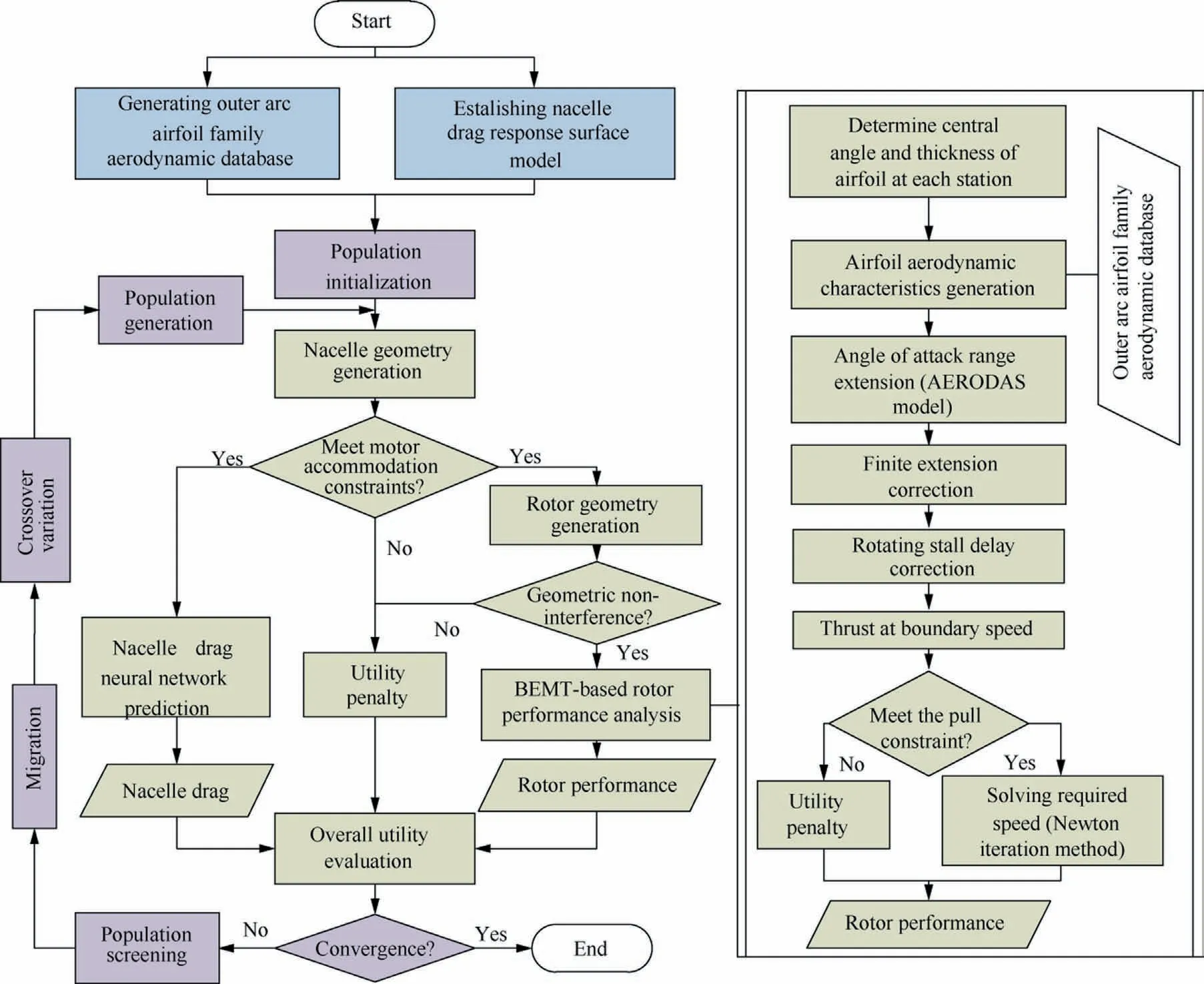
Fig.16 Implementation process of geometrically compatible integrated optimization of rotor and nacelle.
The core utility evaluation module is used to evaluate the utility of each sample in the optimization process.The generated nacelle geometry is first checked to determine whether it satisfies the motor accommodation constraint.If so, the nacelle drag is predicted,and the rotor geometry is constructed based on the geometric compatibility conditions.Otherwise, a penalty value for the utility is assigned and directly transferred to the next sample evaluation.Then, on the premise that the rotor geometry satisfies the blade non-interference constraint,the rotor performance analysis is carried out based on the oblique inflow BEMT method.The process includes the following steps:(A)The central angle and thickness of the outer arc airfoil at each station along the radius are extracted according to the generated rotor geometry;(B)The aerodynamic characteristics of the airfoils at each station are obtained based on the aerodynamic database of the outer arc airfoil family; (C) The obtained aerodynamic characteristics of each airfoil are expanded within the range of the angle of attack,and the finite blade span and the rotating blade stall delay corrections are carried out (see Section 3.2); (D) The matching analysis on the current rotor thrust is performed with the oblique inflow BEMT method.If the matching degree is poor, the utility of the sample is assigned a penalty value.If the rotor thrust constraint is satisfied, the performance parameters such as rotor speed, power, and thrust efficiency that can generate the required thrust are calculated using the Newton iteration method.
So many interesting things in the train, I can t list them all. Individually, I feel the train life is hell6 unforgotten. I think I will never forget it, cherish15 it as one bell in the sea.
According to the nacelle drag predicted by the neural network RSM and the rotor performance calculated by the oblique inflow BEMT method,the overall utility evaluation of the current sample is completed.On this basis, the optimization control module composed of the multi-island genetic algorithm is used to carry out integrated optimization of the rotor and nacelle.
6.Case study and result analysis
Using the proposed method, the geometrically compatible integrated design of the rotor and nacelle is carried out for a 200 kg distributed propulsion tilt-wing UAV (as shown in Fig.1), so that the energy consumption introduced by the rotor and nacelle is as low as possible during the full-profile flight.In this mission profile, the hovering duration is 5 min,the endurance time is 2 h, and the cruising speed is 35 m/s.The tilt-wing UAV provides a total of eight sets of rotors/nacelles of the same size to meet the hovering thrust requirements.The length of the nacelle is set to 0.7 m, and the motor is installed at 20%-50% position along the axial direction of the nacelle.The length of the motor is 0.21 m,the diameter is 0.112 m, and the allowable speed range is 2500–4500 r/min.
6.1.Optimization process and results
According to the process shown in Fig.16,the integrated optimization of the rotor and nacelle is carried out.The response of the design variables, constraints, and objective under the current design conditions is shown in Fig.17.As the optimization proceeds, the hovering energy consumption, the cruise energy consumption, and the total energy consumption are continuously reduced, and the design variables are gradually converged to the corresponding values for optimal performance.After completing 15000 sample calculations (200 samples per generation,75 generations in total),the optimal utility no longer increases and the optimization process is considered to have converged.At this time,the rotor speed is 2660 r/min,the thrust is 244.72 N,the thrust efficiency is 5.56 kg/kW,and the nacelle drag is 0.678 N.The hovering energy consumption,the cruise energy consumption,and the total energy consumption are 3.0 kWh, 0.38 kWh, and 3.38 kWh, respectively.
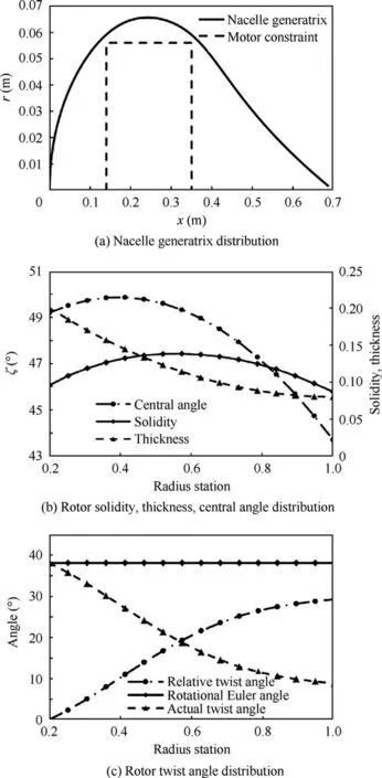
Fig.18 Optimization results: geometry parameters of nacelle and rotor.
The nacelle generatrix control parameter corresponding to the optimal design point ψna={0.05, 0.251, 0.1, 0.251, 0.602,0.05}, the rotor twist angle control parameter ψnz={38.1,7.75, 26.41, 27.37, 29.3}, the central angle control parameter ψc={0.243, 49.87, 49.19, 43.7}, the rotor radius control parameter δRequals 0.5, and the number of blades Nbequals 5.By post-processing of the above results according to the nacelle and rotor shape parameterization method given in Section 2,the key geometric parameters corresponding to the final results of the geometrically compatible integrated optimization are obtained, such as the nacelle profile, the central angle of each rotor section, the relative twist angle, and the rotational Euler angle.The rotor solidity is also obtained from the nacelle profile distribution and the central angle of each rotor section,and the actual rotor twist angle of each rotor section is obtained from the relative twist angle and the rotational Euler angle.The results are presented in Fig.18.The shapes of the rotor and nacelle corresponding to the optimum efficiency is shown in Fig.19.In order to ensure that the folded rotor can be fully incorporated into the nacelle groove, the groove is properly enlarged during the design process, thus leaving a certain gap.In the engineering development stage, the width of this gap can be optimally adjusted by combining the folding mechanism accuracy, machining accuracy, and fit clearance.
In the cruise state, the rotor blades are incorporated into the nacelle, so disturbances on the wing can be ignored.The interference of distributed rotors on the wing mainly occurs in the tilting state.In this state, the rotor slipstream can effectively improve the effective lift coefficient of the wing, so that the tilt-wing UAV can complete the tilting motion with a smaller wing area and lower speed.However, the tilt duration is short compared to the vertical and forward flight durations.Therefore, the performance of the conformal rotor at the two design points of hovering and cruising is mainly analyzed next.
6.2.Performance analysis in hovering state
In order to compare the differences between the performances of the above conformal rotor and the conventional rotor in the hovering state, the conventional rotor optimization design under the same operating conditions is performed based on the NACA-16 series airfoil family.Naturally, the geometry compatibility constraint is removed from the conventional rotor optimization process.The optimized shape of the rotor obtained based on the conventional design is shown in Fig.20.

Fig.20 Optimization results of conventional design based on NACA-16 series airfoil family.
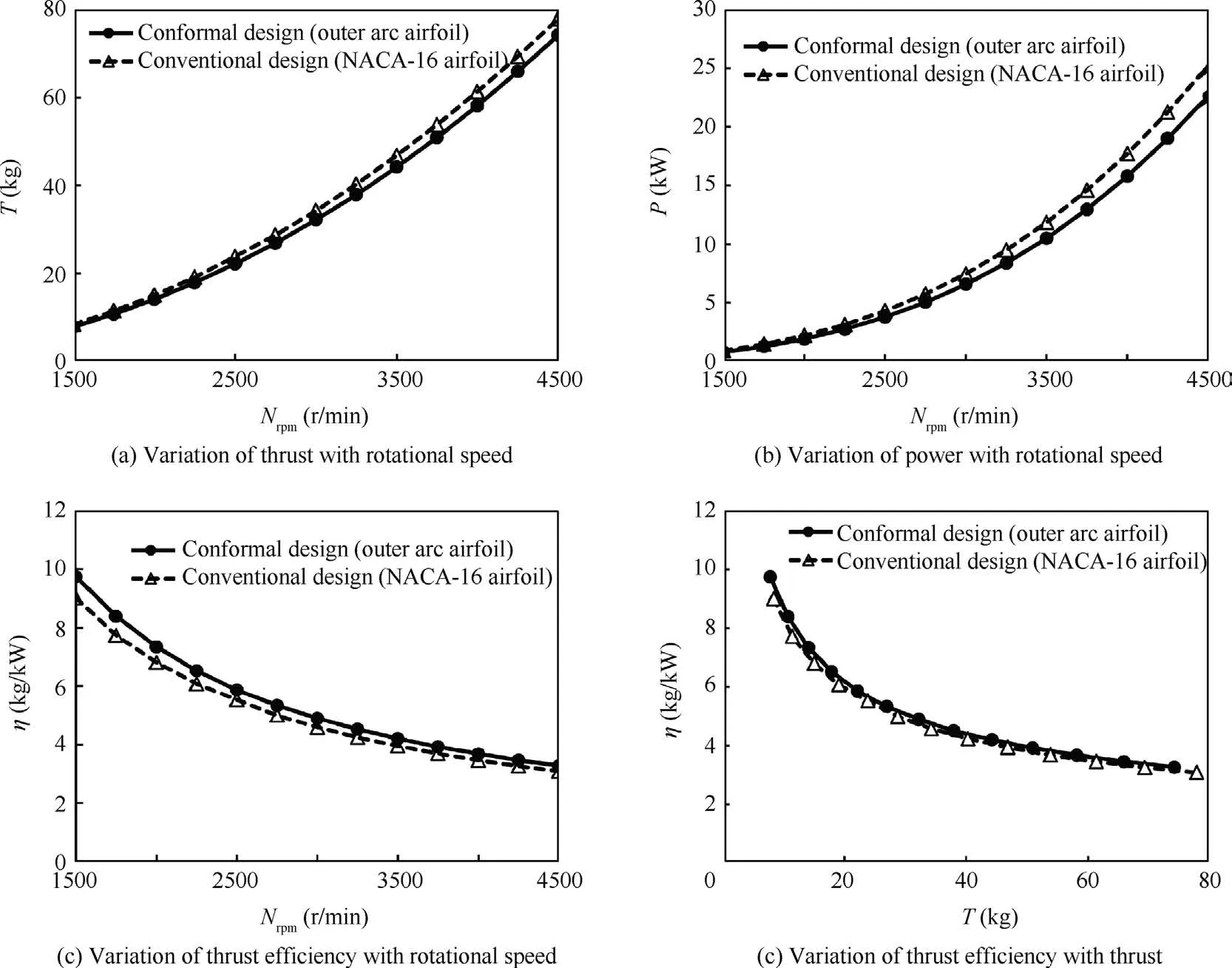
Fig.21 Comparison of performance of conformal optimized rotors and conventional optimized rotors.
Using the oblique inflow BEMT method,the thrust,power,and thrust efficiency of the optimized conformal rotor and the conventional rotor are calculated at different rotational speeds.The results are shown in Fig.21.The overall performance of the two rotors is relatively close in the speed range of 1500–4500 r/min.At the same speed,the conventional rotor based on the NACA-16 series airfoil family has slightly higher thrust and power than the conformal rotor based on the outer arc airfoil family,but the thrust efficiency is lower than that of the conformal rotor.At the design thrust (245 N), the thrust efficiency of the conformal rotor(5.56 kg/kW)is 4.12%higher than that of the conventional rotor (5.34 kg/kW).
The analysis of rotor performance with higher accuracy is carried out based on the CFD method.The numerical calculation meshes of the optimized conformal rotor/nacelle and the conventional rotor/nacelle are shown in Fig.22.Then, the aerodynamic analyses of the two rotors under the design conditions are carried out, and the detailed changes of the flow field during the operation of the two rotors are obtained.The velocity distribution before and after the rotor disk is shown in Fig.23.With the same design requirements, the acceleration effect on the flow field is relatively similar for both types of rotors, despite the large differences in geometry.
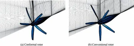
Fig.22 Numerical simulation meshes of two rotors in unfolded state.

Fig.23 Velocity contours of two rotors.
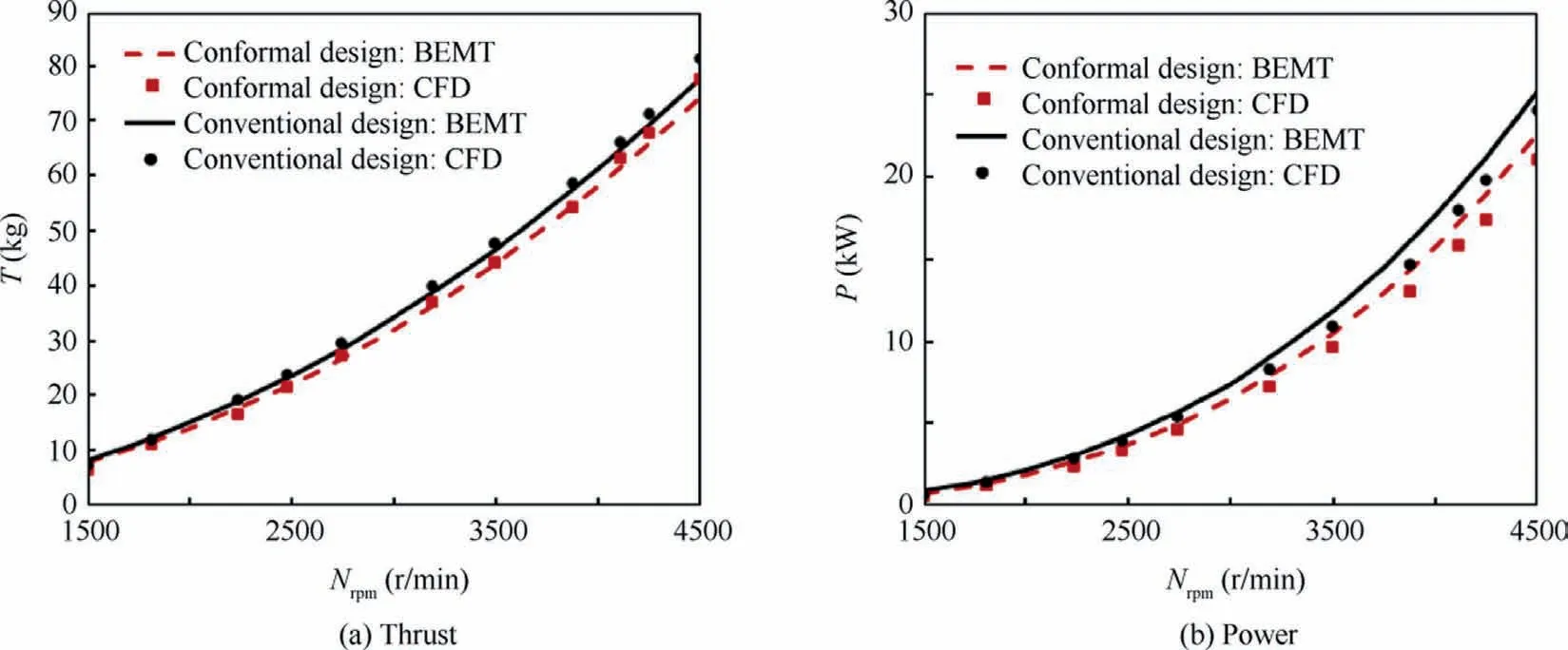
Fig.24 Comparison of results between CFD and BEMT methods.
The performances of the two rotors at different rotational speeds obtained using the BEMT and CFD methods are presented in Fig.24.It can be seen that at the same rotational speed,the thrust obtained by using the CFD method is slightly higher than that calculated by the BEMT method(the range of error is 0.5% to 4.6%), but the absorbed power calculated by the CFD method is slightly lower than that calculated by the BEMT method (the range of error is 2.3% to 7%).Despite the above differences between the CFD and BEMT calculation results,the thrust efficiency of the conformal rotor obtained by the geometrically compatible integrated optimization is still 5.3% higher than that of the conventional rotor at the design point.The result indicates that the geometric compatibility constraints imposed during the rotor/nacelle integrated optimization do not cause deterioration of the rotor performance.On the contrary,since each airfoil in the outer arc airfoil family is optimized individually, they may instead possess higher thrust efficiency compared to the conventional rotor design which uses the airfoil family constructed by scaling with a single optimized airfoil at 70% of the radial position.
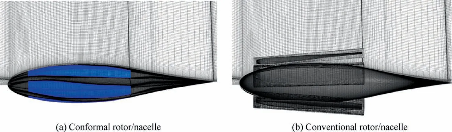
Fig.25 Numerical simulation meshes of two rotors in folded state.
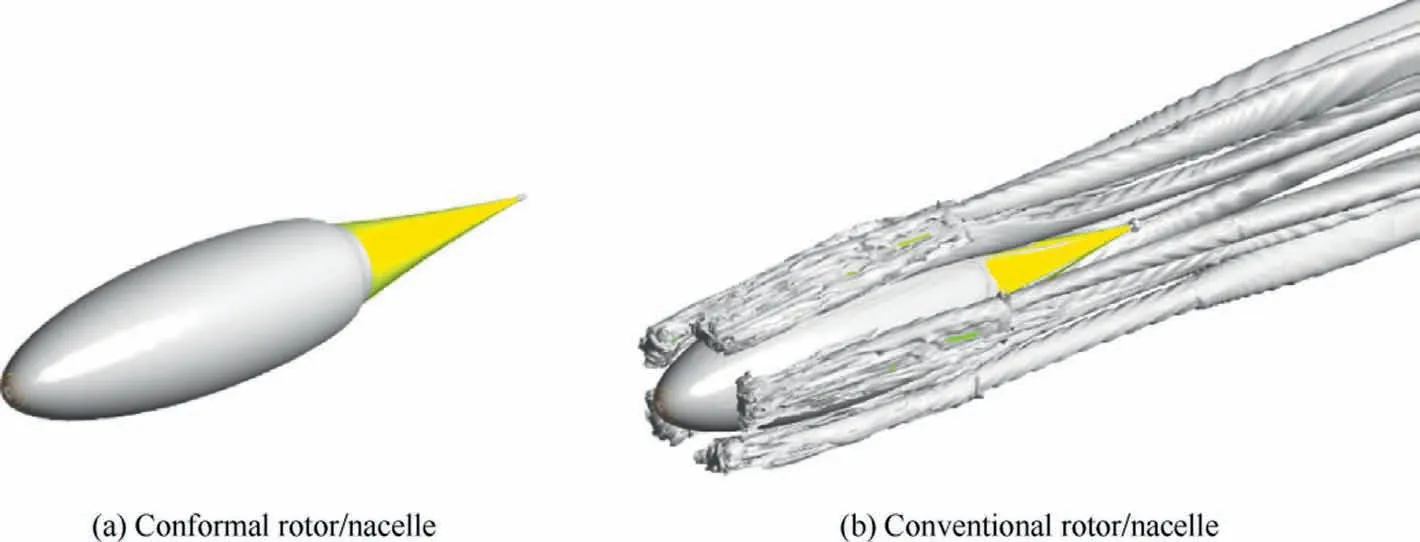
Fig.26 Vortex distribution of the two configurations.
6.3.Performance analysis in cruising state
Although the nacelles obtained by the integrated design and the conventional design have similar generatrix profiles, the drag of the two nacelles in cruise is significantly different due to the configuration differences brought by blade folding.Based on structural mesh and nested mesh techniques, the numerical calculation meshes of the two types of nacelles with folded blades are constructed (see Fig.25).The performance analysis of the two types of nacelles in the cruise state is carried out accordingly.
The vortex distribution of the two configurations under the design conditions obtained by numerical simulation is given in Fig.26.It can be seen that the surface pressure distribution of the nacelle in the conformal rotor folding state is close to that of the single nacelle.However, there is a serious interference between the nacelle and the rotor in the conventional rotor folding state.The turbulent kinetic energy on the rear side of each rotor blade increases sharply, and the flow field quality is seriously deteriorated.
The force measurement results show that the drag of the nacelle in the conformal rotor folding state at the incoming flow speed of 35 m/s is 0.678 N, which is similar to that of the single nacelle.The drag of the nacelle in the conventional rotor folding state reached 2.34 N, which is 3.45 times that of the single nacelle,proving the effectiveness of the integrated rotor/nacelle design for cruise drag reduction.
6.4.Comprehensive performance analysis
According to the optimized design results, the total energy consumption introduced by the eight rotors and nacelles is 3.38 kWh when the distributed propulsion tilt-wing UAV with the conformal rotors and nacelles completes a 5 min hover and 2 h cruise mission.However, the total energy consumption increases to 4.43 kWh if the conventional design result is used.In addition,as the duration of the tilt-wing UAV increases,the reduction in energy consumption brought by the geometrically compatible integrated design is more obvious, as shown in Fig.27.This fully demonstrates the necessity of applying the integrated conformal rotor/nacelle design for the distributed propulsion tilt-wing UAV.
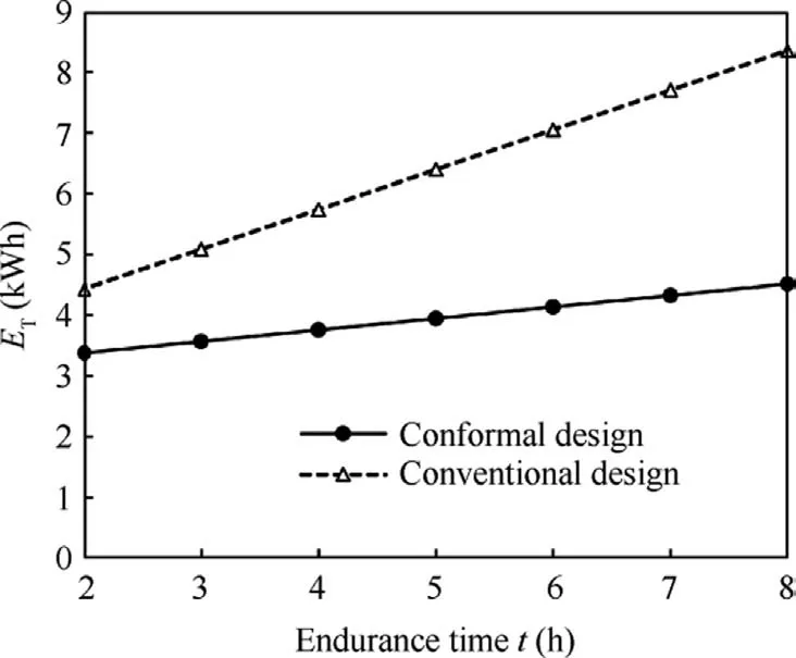
Fig.27 Comparison of total energy consumption of integrated conformal design and the conventional design.
7.Conclusions
(1) A geometrically compatible integrated design method for the conformal rotor and nacelle of the distributed propulsion tilt-wing UAV is proposed in this paper.The nacelle and rotor shape parameterization method satisfying geometric compatibility and the outer arc airfoil family optimization method dedicated to the conformal rotor design are presented.
(2) The geometrically compatible integrated design method can handle complex geometric compatibility constraints and effectively coordinate the aerodynamic efficiency of rotor and nacelle.Using this method, a combination of conformal rotor and nacelle with high rotor efficiency in the unfolded state and low drag in the folded state can be obtained.
(3) The rotor and nacelle geometric compatibility constraints imposed during the conformal rotor design process do not cause deterioration of rotor performance;on the contrary, the conformal rotor has higher thrust efficiency compared with the conventional rotor due to the individual optimization of each airfoil in the outer arc airfoil family.
(4) The integrated conformal design can significantly reduce the overall drag of the rotor and nacelle in the cruise state: the drag of the conventional rotor/nacelle after the blades are folded can reach 3.45 times that of the single nacelle, while the drag of the optimized conformal rotor/nacelle in the folded state can be maintained at a level close to that of the single nacelle.
(5) Compared with the conventional design,the drag reduction effect brought by conformal rotor folding can significantly reduce the overall energy consumption in the whole profile, and the longer the cruise time, the more prominent the energy-saving effect.Therefore, for distributed propulsion tilt-rotor wing UAVs, the longer the cruise time, the stronger the necessity of using the conformal rotor and nacelle.
Declaration of Competing Interest
The authors declare that they have no known competing financial interests or personal relationships that could have appeared to influence the work reported in this paper.
Acknowledgement
This study was supported by the Fundamental Research Funds for the Central Universities (No.56XCA2205402).
 CHINESE JOURNAL OF AERONAUTICS2023年10期
- CHINESE JOURNAL OF AERONAUTICS的其它文章
- Role of unsteady tip leakage flow in acoustic resonance inception of a multistage compressor
- Numerical and experimental investigation of quantitative relationship between secondary flow intensity and inviscid blade force in axial compressors
- Flamelet-like models applied in scramjet combustors: A state of art and prospect
- An improved nonlinear onboard adaptive model for aero-engine performance control
- High-fidelity simulation of blade vortex interaction of helicopter rotor based upon TENO scheme
- Numerical simulation and experimental research on oscillation performance of disc-type jet oscillator