
In-flight deformation measurement for high-aspect-ratio wing based on 3D speckle correlation①
2023-09-12 07:29:56ZHANGXingguo張興國HUBinghuaWANGYuanliangYANHuiMAXiaodongGEQuanbo
High Technology Letters 2023年3期
關(guān)鍵詞:興國
ZHANG Xingguo(張興國),HU Binghua,WANG Yuanliang,YAN Hui,MA Xiaodong,GE Quanbo②?
(?School of Computing,Northwestern Polytechnical University,Xi′an 710072,P.R.China)(??Test Technology Institute,Chinese Flight Test Establishment,Xi′an 710089,P.R.China)
(???School of Logistics Engineering,Shanghai Maritime University,Shanghai 201306,P.R.China)
(????College of Automation,Nanjing University of Information Science & Technology,Nanjing 210044,P.R.China)
Abstract In order to get an effective solution of the in-flight wing deformation measurement for high-wing aircrafts with high-aspect-ratio,a method based on three-dimensional (3D) speckle correlation technique is proposed.Firstly,an in-flight wing deformation measurement system with two sets of conjugate cameras is designed based on structural characteristics and test requirements of high-wing aircrafts with large-aspect-ratio.Secondly,the in-flight wing deformation measurement method based on 3D speckle correlation technique is introduced including three aspects: measuring system and wing datum calibration,speckle image matching and 3D reconstruction,and wing deformation analysis.Finally,ground simulation test of dynamic deformation measurement of a scaled model wing and flight test of dynamic deformation measurement of a large transport wing are carried out.The test results show that the measuring accuracy of single point coordinate in ground simulation test is better than 0.1 mm/m,in the airborne vibration environment,the static single-point positioning accuracy is better than 5 mm,and the in-flight wing deformation measurement data is well received by the flight test engineers.This method can satisfy the requirements of stability,reliability,high precision,non-contact and full-field measurement for dynamic deformation measurement of aircraft wing with high-aspect-ratio.
Key words: high-aspect-ratio,three-dimensional (3D) speckle,wing datum
0 Introduction
Aircraft wing dynamic deformation is one of the key test contents of flutter airworthiness certification and flight test subjects such as aeroelastic theory research, aircraft aeroelastic mechanics analysis, load analysis,etc[1].Due to the influence of aerodynamic forces during flight[2],the larger wings undergo larger elastic deformation,mainly including torsion and bending deformation.These significant deformations can cause changes in the size and distribution of the external load of the wing,and even cause changes in the distribution of internal structural loads on the wing lifting surface,leading to the deviation of the aircraft wing functioning state from the design state.It could affect the aircraft performance of the aircraft and even endanger the aircraft safety and lives[3-4].Therefore,it is of great significance to test the dynamic deformation of the wing,and for the current aircraft design,the deformation measurement data in the real flight environment is urgently needed as a support for research such as the active use of deformation,computer control of variable wing camber,and optimization of the theoretical calculation models.
The three-dimensional (3D) speckle image related visual measurement technology has been applied in some fields by virtue of its advantages of fast measurement speed,high accuracy,strong real-time performance,insensitive ambient light,and non-contact fullfield measurement[5].In terms of wing deformation measurement,the European National Aeronautical Laboratory (NLR) implemented wing deformation measurement during the Airbus A380 flight tests based on digital image correlation technology in 2010[6].European advanced flight status testing technology (AIM2)successfully applied the in-flight dynamic deformation image measurement technology based on the three-dimensional speckle image to the flight test of the Evektor VUT-100 Cobra aircraft in 2013[7].The image pattern correlation technique (IPCT) was applied to the glider test bed within the scope of AIM2 and the flight test was performed to measure the wing deformation[8].In China,the measurement of the aircraft wing deformation based on the three-dimensional speckle patterns image remains in theoretical research and simulation stage,which has not been applied to actual flight measurement[9].Relevant engineers of Chinese Flight Test Establishment conducted research and analysis on the theory and application of full-field three-dimensional transient deformation measurement technology based on three-dimensional speckle images[10-11].Aiming at the characteristics and flight test requirements of high-wing aircrafts with large-aspect-ratio,some technical problems such as the difficulty in determining the installation position of the measurement equipment and the difficulty in accurately measuring the three-dimensional dynamic deformation of a large-scale curved surface under a vibration environment are solved,and a solution of in-flight wing deformation measurement for highwing aircrafts with large-aspect-ratio is designed and built.
1 Measuring system
Aiming at the structural characteristics and testing requirements of high-wing aircrafts with large-aspectratio,combined with the general requirements of flight test image testing,a dynamic deformation measurement system for high-wing aircrafts with large-aspect-ratio is constructed.Due to the large wingspan of the aircraft,multiple cameras are required for relay measurement.At the same time,due to the characteristics of the highwing,the cameras can only be installed on the vertical tail of the aircraft.Considering the deformation and vibration of the vertical tail,and the feasibility of the installation,the vertical tail front is selected as the cameras installation position.Therefore,the system adopts left-right relay and up-and-down intersection to achieve the deformation measurement of the entire wing.The lens focal length and the number of combined cameras are compromised according to the vertical tail structure information,the distance between the wing and the vertical tail,the camera parameters,the test accuracy requirements,etc.In addition,due to the high-frequency vibration of the vertical tail during flight,the position and attitude of the cameras shift accordingly.In order to ensure the measurement accuracy, the conjugate camera groups are designed,with the middle camera in each group as the reference camera to correct the exterior orientation elements offset of remaining cameras to achieve system vibration compensation.And,the coding marks are arranged in the rigid part of the aircraft and the reference camera field of view as the measurement reference area for real-time calibration of the reference camera.
To realize the motion monitoring and deformation measurement processing and analysis of the wing,the dynamic deformation measurement system of high-wing aircraft with large-aspect-ratio is mainly composed of airborne image acquisition subsystem, camera and measurement reference calibration subsystem and image data processing and analysis subsystem (as shown in Fig.1).Among them,the airborne image acquisition subsystem is used for wing surface processing (spraying of speckle and coded marking points) and high definition(HD)video data acquisition of the wing status during the flight; the camera and measurement reference calibration subsystem is mainly used for measurement of the wing reference state and marker points in the measurement reference area,and calibration of two conjugate camera groups; the image data processing and analysis subsystem is mainly used for feature extraction and image correlation matching of the HD video data, vibration correction/compensation of conjugate camera groups,forward intersection and 3D reconstruction of the wing,3D dynamic display and data analysis of the wing deformation.
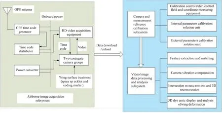
Fig.1 Composition of wing dynamic deformation measurement system based on 3D speckle correlation for high-wing aircraft with large aspect ratio
2 Measuring method
2.1 Three-dimensional speckle correlation
Three-dimensional speckle correlation is a combination of two-dimensional digital speckle correlation and binocular stereo vision technology.Two cameras are used to capture the speckle patterns on the surface of the object before and after deformation from different angles.By pre-processing,meshing,and correspondence sub-areas matching of the speckle images,the two-dimensional coordinates of the center points of the subareas before and after deformation are calculated,then 3D reconstruction is performed based on the calibration parameters of the two cameras to obtain the three-dimensional spatial coordinates of these points before and after deformation,thus the three-dimensional deformation information can be obtained.The key technologies related to 3D speckle mainly include the following four items: image acquisition, camera calibration, image matching,and 3D reconstruction[12].
The implementation of the dynamic deformation measurement method of high-wing aircraft with large aspect ratio based on three-dimensional speckle correlation is around these four key technologies.The image acquisition is to obtain images of the speckle area and the measurement reference area on the wing surface before and after deformation by installing two conjugate camera groups.The image quality directly affects the subsequent image processing.The camera calibration is to obtain the interior orientation elements,distortion parameters,relative exterior orientation elements and absolute exterior orientation elements of the two conjugate camera groups,which is the support and premise of the entire measurement system for image matching and 3D reconstruction.The image matching includes two links,i.e.stereo matching and two-dimensional matching.The stereo matching is for speckle images in the same deformation state,which is to match the speckle images obtained by two intersecting cameras.While the two-dimensional matching is for speckle images in different states,which is to match the speckle images of different states obtained by the same camera.The 3D reconstruction is to calculate the spatial coordinates of the speckle based on the forward intersection calculation model and the speckle coordinates obtained by stereo matching,then,the data obtained from multiple intersection cameras are stitched together to obtain the 3D reconstruction of the complete wing.In order to achieve the measurement of the dynamic deformation of the wing,the reference state of the wing needs to be calibrated.The results of the 3D reconstruction of the wing in-flight are compared with the reference state to finally obtain the dynamic deformation of the wing.
2.2 Measurement system and wing reference calibration
2.2.1 Calibration parameters
The parameters that the measurement system needs to calibrate are the follows[13].
(1) Elements of interior orientation (principal point of photograph (x0,y0) and focal length(f) ).
(2)Distortion parameters[13](radial distortion coefficients (k1,k2,k3),tangential distortion coefficients(p1,p2) and thin prism distortion coefficients (s1,s2)).
(3)Elements of relative exterior orientation (position and attitude relationship of remaining cameras relative to the the reference camera in a conjugate camera group).
(4)Elements of absolute exterior orientation (position and attitude parameters of a conjugate camera group in object space coordinate system),which is referred to as exterior orientation elements.
The wing reference calibration is to construct the wing deformation reference coordinate system in the horizontal state of the aircraft,as the object space coordinate system for calibration of the measurement system,and obtain the three-dimensional coordinates of the coded marker points arranged on the measurement reference area and the wing in the reference coordinate system,as the datum for data processing and comparative analysis.
2.2.2 Calibration method
The calibration of the measurement system includes ground static calibration and real-time calibration of the dynamic exterior orientation elements.Considering that the system have a long shooting distance and a large field of view,the bundle adjustment method based on the control ruler within the foreground depth range is adopted for the interior orientation and distortion parameters calibration,the space resection method based on the large three-dimensional control field in the measured area is used for the calibration of the parameters listed in (2) -(4) in subsection 2.2.1,and the real-time calculation and transmission method based on the fixed points arranged on the measurement reference area is involved for real-time calibration of the dynamic exterior orientation elements.
(1) Internal parameters calibration of long-distance and large-field cameras based on the control ruler within the foreground depth range.
Find a position where the imaging is clear and the imaging size of the marker point on the ruler exceeds 8 pixels in the foreground depth range of each camera.Then,rotate and translate the control ruler in the camera field of view,and collect the corresponding sequence images as the calibration images,which are processed by the identification,positioning and matching of the image marker points,and then combine the space constraints between the marker points to realize the camera calibration calculation.
If the distance between the two marker points on the ruler is set as the constraint,according to the collinear condition equation,the calibration solution model can be abbreviated as[14]
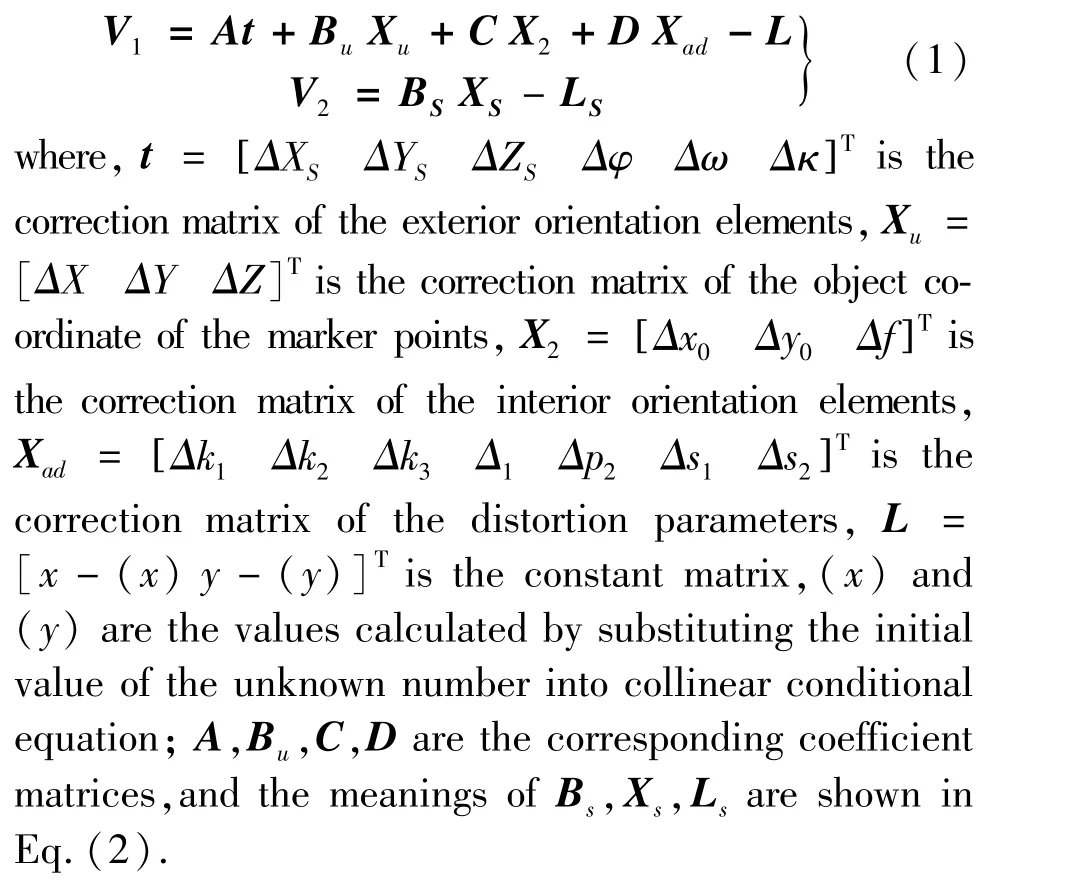
In the process of collecting calibration images,it should be noted that when changing the position and attitude of the calibration ruler,there should be changes in both the relative angle and the relative translation between the captured images.Generally,20 to 30 calibration images are collected to participate in the calibration calculation.
Since this method uses a calibration control area that is far away from the measurement area,the distortion parameters obtained by the calibration calculation cannot fully reflect the image distortion of the measurement area,so it is necessary to recalibrate the distortion parameters based on the control of the measurement area.
(2) External parameters calibration based on large three-dimensional control field in the measured area.
The core of the calibration based on large threedimensional control field in the measured area is space resection.Based on a few images covering a certain number of control points collected from the same perspective and the object space coordinates of the control point,according to the collinear conditions equation,the calibration parameters can be obtained.
For the reference camera,the error equation is
V=At+D Xad-L(5)where,the meaning of each parameter is the same as Eq.(1).
For the remaining cameras of the conjugate camera group,set the position and attitude matrix of one of these cameras relative to the object space coordinate system forTc,Rc,the position and attitude matrix of the reference camera relative to the object space coordinate system forT,R,and the position and attitude matrix of the camera relative to the reference camera coordinate system forTr,Rr,there is an equivalent relationship between them as shown in Eq.(5),combined with the collinear condition equation,the error Eq.(6) for calculating the relative exterior elements of the remaining cameras can be derived.
where, the meaning oftandXadis the same as Eq.(1),Tris the correction matrix of the relative exterior orientation elements of the remaining cameras;B,CandEare the corresponding coefficient matrices;L′is the constant matrix.
Combining Eq.(4) and Eq.(6),the exterior orientation elements and relative exterior orientation elements and distortion parameters of the system can be obtained by least square iterative calculation according to the image plane coordinates and object space coordinates of the control points[15].
(3) Real-time dynamic calibration of cameras based on fixed points.The position and attitude of the reference camera can be obtained in realtime by space resection calculation according to the fixed points arranged on the measurement reference area (at this time,Xad= 0 in Eq.(4)),then,the dynamic exterior orientation elements of all cameras can be calculated according to Eq.(5), and the relative exterior orientation elements of the remaining cameras can be obtained by ground static calibration of the measurement system.
The premise of achieving high-precision dynamic exterior orientation elements calibration of the measurement system is to design the conjugate camera group,that is,the cameras can ensure the mutual position and attitude relationship unchanged during flight,and the data acquisition of the cameras can be strictly synchronized.
2.3 Image matching
The digital speckle correlation matching method is introduced to match the corresponding points on the two images by using random speckle as the feature.The square reference sub-region (containing more than one elliptical speckle pattern) of (2n+1) ×(2m+1) pixels in the reference image is selected to find the target sub-region with the most similarity to the reference subregion in the target image.The centers of the two subregions which are successfully matched can be regarded as corresponding points.The principle of digital speckle correlation matching is shown in Fig.2.
The similarity evaluation between the reference sub region and the target sub region can be transformed into the process of solving the similarity coefficient.In the actual experiment,the light intensity of the obtained speckle image changes with time,so the correlation function (ZNSSD function),such as Eq.(7), is used to define the similarity between the two sub regions of the matching image.ZNSSD can eliminate the influence of the linear change of image gray caused by the change of light.It is insensitive to the linear change and offset of gray level,and has good anti-interference performance[12].
When performing correlation matching,the firstorder displacement function is often used to represent the mapping relationship between the points in the two sub-regions,including the displacement (u,v) of the point(x′,y′)relative to the point (x,y) in thexandydirections and the displacement gradient (ux,uy,vz,vy) from the point(x′,y′)to the point (x,y).According to Fig.2,X=[u ux uy v vx vy r0r1]is taken as the matching parameter vector to be solved,and the minimum value ofCZNSSDis obtained by the iterative least squares method to achieve sub-region matching.For the matching of full time series state images,the matching strategy of cross matching between stereo matching and two-dimensional matching is adopted until the stereo matching of the speckle subsets in all states is completed[16-20].
2.4 3D reconstruction and wing deformation analysis
On the basis of the ground static calibration and real-time calibration of the measurement system,the 3D reconstruction of the wing airfoil is realized based on the forward intersection measurement principle.Since the measurement of the entire wing surface is carried out by the up-and-down two sets of cameras for segmented intersection measurement,there is a small overlap between adjacent segments,which is located at the edge of the camera imaging.In order to improve the measurement accuracy of the overlapped part,here,the up-and-down binocular intersection measurement and the left and right four-eye intersection measurement are used for positioning calculation,thus,the single wing can obtain five data segments,and then based on these five data segments,the high-precision measurement data of the complete wing surface of the single side can be obtained by splicing and fusion processing.
(1) Binocular intersection measurement is based on point projection coefficient method.
(2) Four-eye intersection measurement is based on collinear conditional equation method,which is used to improve the accuracy of binocular intersection measurement in the edge area of the image.
(3) Splicing and fusion processing is a data synthesis processing which adopts the optimal fusion strategy and takes the four-eye intersection measurement results as the optimal data.
Taking the wing reference calibration data as the absolute reference state and the measurement data of the ground driving state before the aircraft slides out of the day as the relative reference state,combining the 3D reconstruction results of the effective flight segment of the test flight,the wing deformation and deformation process are analyzed.When analyzing with point elements,a point or multiple points spatial coordinates data is extracted from the wing 3D reconstruction results of the effective flight test phase,and the deformation amount and deformation process curve can be obtained by the difference operation between the data and the reference state data.
3 Verification of measurement method in ground simulation test
In order to verify the feasibility and accuracy of this method,a wing dynamic deformtion measurement simulation test system consisting of two upper and lower groups of 4 cameras and model wing was constructed in the laboratory.Through system construction,camera calibration,image data acquisition and processing of the model wing deformation process,the system's static calibration accuracy,real-time dynamic calibration effectiveness and reliability,speckle detection and matching capabilities,data splicing and fusion processing accuracy,and three-dimensional deformation analysis and display effects of the wing have been verified.
Fig.3 is an image of a single-sided wing model sprayed with a speckle pattern taken by one of the cameras.Fig.4 is a three-dimensional display of the deformation measurement results at a certain time during the movement of the wing model.It can be seen from Fig.4 that this method can effectively realize the measurement and analysis of wing deformation.
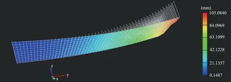
Fig.3 Unilateral model wing
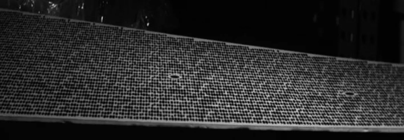
Fig.4 Deformation measurement results at a certain time during the movement of the model wing
Take four points on the wing surface for point analysis,stabilize the wing at a certain time,then measure the three-dimensional coordinates of these four points with coordinate measuring equipment and compare it with the data measured by the wing dynamic deformation measurement system, and the result indicates: the single-point positioning accuracy is better than 0.1 mm in ground simulation test of wing deformation measurement based on three-dimensional speckle correlation.Considering the wing span length and photography distance of a large transport aircraft,the wing dynamic deformation measurement accuracy of the aircraft can be estimated: ignoring the environmental factors (vibration,illumination,etc.),the single-point positioning accuracy of this method is better than 2.5 mm,which is better than the accuracy requirements of the test mission.So the method is feasible for flight test of wing dynamic deformation measurement.
4 Flight test verification
4.1 Modification and calibration of the measurement system
Taking a large transport aircraft as an example,based on the information of the vertical tail structure of the aircraft,the distance between the wing and the vertical tail,the selected camera parameters,and the accuracy requirements of the test,etc.,a deformation measurement system composed of upper and lower conjugate camera groups (each group contains 5 cameras) is built to realize the entire wing deformation measurement through intersection and relay measurement.The installation position of the two conjugate camera groups at the vertical tail front and wing surface treatment,the wing surface is sprayed with speckles and coding marks,especially on the ribs that are the focus of attention should be sprayed with coding marks,which are used for the wing reference calibration and the wing deformation point analysis.The pattern of the speckles and coding marks should be stretched based on the angle and distance between the camera optical axis and the measured plane to improve the recognition efficiency and matching reliability under large inclination photography.
After communicating with the aircraft design,development,production and refit departments,the measurement system can be installed on the vertical tail without affecting the aerodynamic condition of the aircraft by replacing the vertical tail front skin,opening light-window for cameras,installing optical glass,and installing a camera fixing bracket inside the vertical tail.
4.2 Calibration of the measurement system
Due to the small light-window and the narrow internal space of the vertical tail of the aircraft,the commonly used way of changing the camera position and angle to achieve the calibration of the camera internal parameters cannot work here.Therefore,after the measurement system is installed on the aircraft,the joint test is normal when the field of view,aperture and definition of each camera are adjusted properly to ensure that the complete wing surface can be covered and clear imaging.Then,fix the cameras and perform calibration of the measurement system and wing reference.
The implementation process of the measurement system and wing reference calibration is as follows.
(1)Through the high-altitude vehicle,the calibration control ruler is continuously changed with variants in position and attitude in the camera foreground depth range.Generally,the images of the calibration control ruler in 20 states are collected as internal parameters calibration images; in this way,the internal parameters calibration images of each camera are collected.
(2)Carry out the leveling of aircraft in the state of empty fuel, use coordinate measuring equipment to measure the coordinates of the aircraft axis reference point to determine the wing deformation reference coordinate system,and then measure the coded marker points coordinates on the wing as the wing reference calibration data.
(3)Arrange a control field near the wing to make more than 8 coded control points evenly distributed in each camera field of view,measure all the coded points coordinates as camera calibration control data; for each camera,continuously collect 10 control field images as external parameters calculation images.
(4)According to the method proposed above,the calibration calculation image is processed to obtain the calibration parameters of the measurement system.
(5)Calibration accuracy analysis and evaluation,select part of the coded marker points arranged on the wing as check points,compare and analyze the measured coordinates with the calculated coordinates obtained based on the forward intersection principle to achieve the actual accuracy verification and evaluation of the measurement system calibration.As shown in Table 1,the static measurement accuracy of the system on the ground is better than 1 cm.
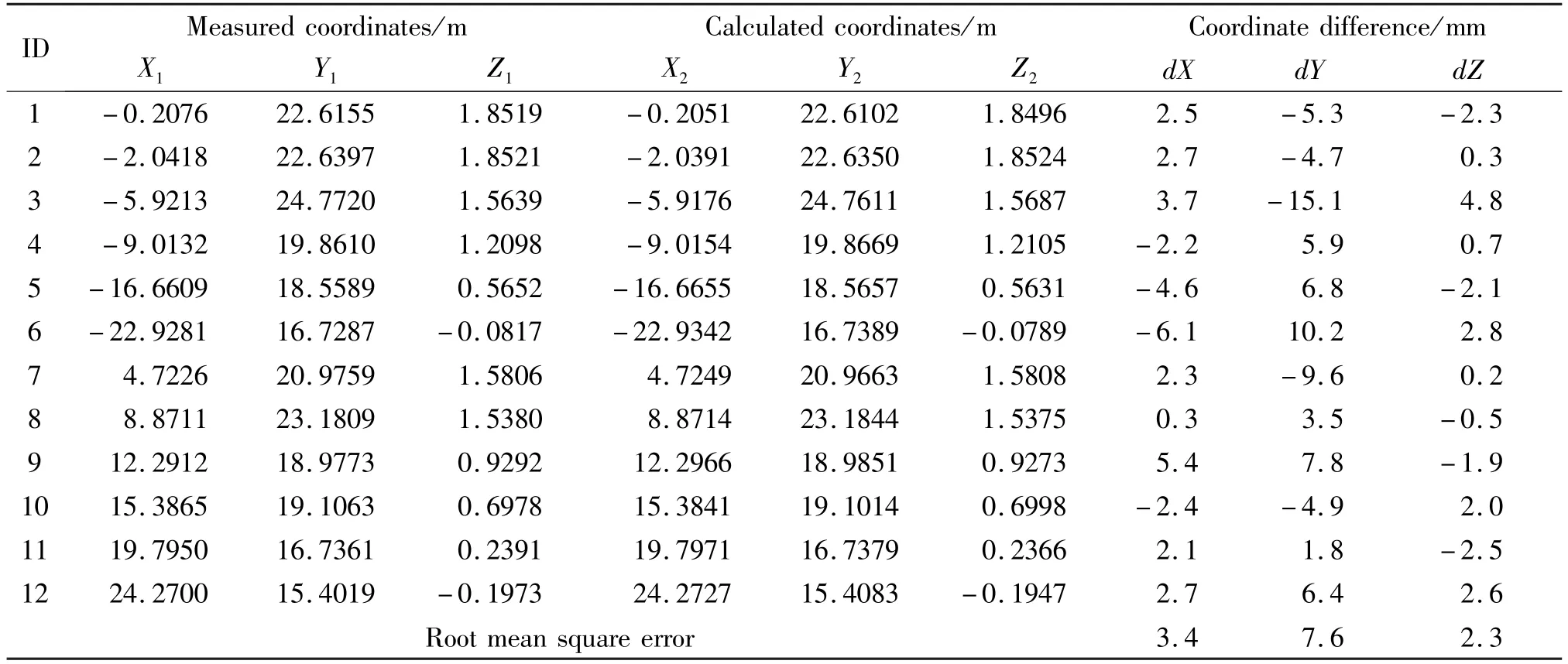
ID Measured coordinates/m Calculated coordinates/m Coordinate difference/mm X1 Y1 Z1 X2 Y2 Z2 dX dY dZ 1 -0.2076 22.6155 1.8519 -0.2051 22.6102 1.8496 2.5 -5.3 -2.3 2 -2.0418 22.6397 1.8521 -2.0391 22.6350 1.8524 2.7 -4.7 0.3 3 -5.9213 24.7720 1.5639 -5.9176 24.7611 1.5687 3.7 -15.1 4.8 4 -9.0132 19.8610 1.2098 -9.0154 19.8669 1.2105 -2.2 5.9 0.7 5 -16.6609 18.5589 0.5652 -16.6655 18.5657 0.5631 -4.6 6.8 -2.1 6 -22.9281 16.7287 -0.0817 -22.9342 16.7389 -0.0789 -6.1 10.2 2.8 7 4.7226 20.9759 1.5806 4.7249 20.9663 1.5808 2.3 -9.6 0.2 8 8.8711 23.1809 1.5380 8.8714 23.1844 1.5375 0.3 3.5 -0.5 9 12.2912 18.9773 0.9292 12.2966 18.9851 0.9273 5.4 7.8 -1.9 10 15.3865 19.1063 0.6978 15.3841 19.1014 0.6998 -2.4 -4.9 2.0 11 19.7950 16.7361 0.2391 19.7971 16.7379 0.2366 2.1 1.8 -2.5 12 24.2700 15.4019 -0.1973 24.2727 15.4083 -0.1947 2.7 6.4 2.6 Root mean square error 3.4 7.6 2.3
4.3 Flight test measurement implementation process
Flight test processes of wing deformation measurement of a large transport aircraft include the following steps.
(1)Video data acquisition: collect the video of the wing stable state about 20 s when the aircraft is preparing to slide out as the wing relative reference state data,and collect the video of the wing deformation process caused by the aircraft maneuvering as the wing deformation state data.
(2)Video data processing: import the wing relative reference state data collected by all cameras into the image data processing and analysis subsystem,create the speckle area,select the image matching sub-region,and then perform two-dimensional matching and stereo matching,combined with the camera calibration results,3D reconstruction is achieved based on the forward intersection to obtain the wing relative reference data; similarly,obtain the wing deformation data based on the wing deformation state data.
(3)Wing deformation analysis: use the wing reference calibration data as the wing absolute reference state data and combine it with the wing relative reference data and deformation data to perform the quantitative and process analysis of wing deformation.
4.4 Analysis of flight test results
After image matching and 3D reconstruction,the deformation measurement data of the wing surface corresponding to the defined speckle area at different time is obtained (as shown in Fig.4),and the 3D visualization and playback of the data are performed in time series to realize the reproduction of the entire deformation process of the wing;select the marker points sprayed on the wing ribs for point analysis to obtain the relevant information such as the deformation curve,maximum deformation,deformation direction and so on.
Based on the relative reference data obtained in a flight test,select the points on the middle wing and the wing tip for point analysis,and observe the changes of each point with time in the three-dimensional coordinates.In the case of statistics,it is concluded that the three-dimensional coordinate floats are all within 5 mm,and the minimum is within 2 mm.Fig.5 is the three-dimensional coordinate change curve of the relative reference data of a certain point on the wing tip.
It can be concluded that in spite of the vertical tail vibration the measurement accuracy under the airborne environment is better than 5 mm by the system vibration compensation.Combined with the single-point positioning accuracy obtained from the ground simulation test,it can be evaluated that the measurement accuracy of this method can meet the requirements of in-flight wing deformation measurement under the premise of obtaining high quality video data.
The same point as that in Fig.6 is selected to analyze the wing deformation measurement data of the aircraft during maneuvering.
The absolute reference data of this point can be extracted from the wing reference calibration data,which is(24.27 m,15.4019 m,-0.1973 m).
The relative reference data of this point can be obtained by taking the average value of about 20 s data,which is (24.243 m,15.402 m,-0.374 m).
The deformation measurement data curve of this point is shown in Fig.6.
From Fig.6,especially theZ-coordinate data curve,it can be clearly noted that the wing state during level flight and the wing tip deformation during the maneuvering process (including the number of aircraft maneuvering actions,the direction and amplitude of wing deformation,etc.),and the actual deformation of wing tip can be obtained by combining with the absolute reference data and relative reference data of the point.The reliability of the data can be further evaluated by comparing the wing deformation data with the aircraft overload data.
5 Conclusion
In this paper,an accurate and effective image measurement method of in-flight wing deformation for high-wing aircraft with large-aspect-ratio is introduced systematically,and also verified by flight test.Digital speckle-related image measurement method is involved here,and the problems of large image distortion and high matching difficulty under large inclination photography are solved by preparing stretched digital speckles and coding marks.In the meanwhile,the conjugate camera system design,camera combination calibration and camera dynamic calibration method based on the measurement reference area are innovatively used to solve the problem of real-time position and attitude correction of the measurement system under vibration environment,and finally the accurate 3D reconstruction and deformation measurement of the entire wing is realized.Compared with the method in Refs[17-26],the proposed method puts forward a practical and reliable solution based on the joint test of 3D speckle and conjugate camera group and the flexible high-precision calibration of large field of view,aiming at the needs of large wing deformation measurement in flight test environment,which can achieve high-precision measurement of 3D dynamic deformation of complete wing.The flight test results prove that this measurement system can achieve a static single-point positioning accuracy of better than 5 mm under the airborne vibration environment; the matching of the wing deformation measurement data and the aircraft overload data meets the consistency conditions,which is confirmed and praised by test flight engineers.It provides reliable data support for the structural load and strength flight test of a large transport aircraft,as well as the aeroelastic correction technology research of wing load,and also provides strong technical support for future related research topics of large passenger aircraft,unmanned aerial vehicles and other projects.
猜你喜歡
心聲歌刊(2022年4期)2022-12-16 07:11:00
心聲歌刊(2021年5期)2021-12-21 06:33:36
音樂天地(音樂創(chuàng)作版)(2021年3期)2021-05-25 12:05:08
衡陽師范學(xué)院學(xué)報(2020年4期)2020-05-18 06:42:32
中國水土保持(2018年10期)2018-10-16 05:02:54
鐵道通信信號(2018年2期)2018-04-18 12:18:16
心聲歌刊(2018年1期)2018-04-17 07:22:54
飲食科學(xué)(2017年12期)2018-01-02 09:23:22
環(huán)球市場信息導(dǎo)報(2017年34期)2017-09-08 01:19:58
東方考古(2017年0期)2017-07-11 01:38:26
 High Technology Letters2023年3期
- High Technology Letters的其它文章
- End-to-end aspect category sentiment analysis based on type graph convolutional networks①
- A wireless geophone based on STM32①
- Research on system combination of machine translation based on Transformer①
- The relationship between extra connectivity and t/k-diagnosability under the PMC model①
- Deep reinforcement learning based task offloading in blockchain enabled smart city①
- Design of two-dimensional spatially coupled LDPC codes for combating burst erasures①