
Structural design and modal behaviors analysis of a new swept baffled inflatable wing
2023-07-04 08:02:08NuoMaLiLiuFanminMengJunhuiMeng
Defence Technology 2023年6期
Nuo Ma, Li Liu, Fanmin Meng, Junhui Meng
School of Aerospace Engineering, Beijing Institute of Technology, Beijing 100081, PR China
Keywords:Inflatable wing Structural design Wet mode Flutter analysis
ABSTRACT
1. Introduction
By maintaining a holding pattern in the air for a long time and rapidly attacking ability,the loitering munition can attack non-lineof-sight targets with exact time, attitude, and direction, which is considered to be rapidly changing the battlefield[1].It is difficult to balance the suppression and damage performance of loitering munitions due to the limited size, weight, and cost [2], because of the contradiction between the fixed configuration of loitering munitions and different tasks. Specifically, loitering munitions for reconnaissance and electronic warfare sacrifice speed for longer flight time, while loitering munitions for attack need higher dynamic performance to achieve accurate strikes against time sensitive targets[2].Therefore,realizing more diversified performances(especially speed) and functions with limited volume will be the main development direction of loitering munitions in the future.
The inflatable wing is a flexible inflatable membrane structure applied to the aerodynamic surface of aircraft [3—5]. It is suitable for loitering munitions because of their advantages of lightweight,cabinet storage volume,and rapid deployment.For example,the I-2000 UAV achieved a 42.7% weight reduction by replacing rigid wings with inflatable wings [3]. Due to the high flexibility, the inflatable wing can achieve adaptive change in span length and even rapid discard by pneumatic actuation.Such structural features make the inflatable winged loitering munitions have the potential to achieve wider range of available speeds and multi-mission capacity in flight, as shown in Fig.1. Obviously, the performance of inflatable structures is faced with more severe challenges due to various mission conditions. Considering the limitation of the traditional scheme,the structure of the inflatable wing needs to be redesigned.

Fig.1. Flight profile of warpable inflatable winged loitering munitions.
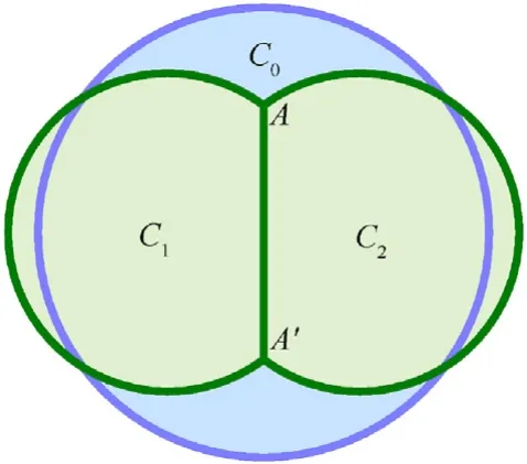
Fig.2. Distorted section of a closed membrane structure with a flexible baffle restraint.
Different from the traditional wing supported by the skeleton with adamant material, the inflatable wing is composed of inflatable beams formed by high strength membranes.In particular,the airfoil can be taken shape by proper arrangement and restraint of the inflatable beams’ layout [6]. These features result in a prominent difference in design procedures compared to the traditional rigid wing,which cannot be ignored in the application.To be compatible with the bubble effect of the inflatable membrane,the target airfoil of the inflatable wing is approximated by a series of inscribed circles [7—9]. Therefore, the designed inflatable airfoil will form a rippled surface, resulting in deterioration of the aerodynamic characteristics,and more baffles should be used to remedy the airfoil, especially at the trailing edge [10]. Thus, the center of gravity is moved toward the trailing edge, which will further deteriorate the flutter performance of the inflatable wing. The bearing capacity of the inflatable structure is directly related to its diameter and inflation pressure [10], and the stiffness distribution of the inflatable wing is jointly determined by the inflatable beams.Under the constraint of airfoil,the stiffness distribution of inflatable wing is most independent of the number and distribution of inflatable beams, which leads to the worse designability of aeroelastic performance. With the increasing of the flight speed, the aeroelastic performance of inflatable winged loitering munitions is put forward a higher requirement. Therefore, it is an important issue to improve the aeroelastic performance of the inflatable wing to ensure its stable flight.
For different requirements, scholars have developed and redesigned the structure of inflatable wings, and certain results in corresponding indicators have been achieved [11—13]. However,most of the research on new configurations of the inflatable wing are aimed to improve the bearing capacity or reduce structure mass, while the aeroelastic performance is neglected. To improve the aeroelastic properties of the wing structure, the aeroelastic tailoring technology has been developed by scholars [14,15]. By designing the order, number, and fabricating direction of the composite material layers laid on the wing structure, a targeted design of the stiffness distribution and the desired response under aerodynamic loads can be realized [16—18]. As the basic bearing membrane structural element of the inflatable wing,the inflatable beams shown anisotropic mechanical properties,and the inflatable wing with better aeroelastic performance is excepted be realized by changing the baffles sweep angle of the inflatable beams.However,the designed stiffness distribution is still difficult to be implemented easily due to the complexity of geometry.
The inflatable beams will remain cylindrical after inflation according to the bubble principle [9]. Under the assumption of the swept arrangement, the inflatable beams have continuously changing chordwise positions, and the uniform cylindrical beam will not be able to meet the requirement of continuous thickness variation. Therefore, the geometry realization remains the main difficulty in implementing the designable stiffness distribution design based on the swept arrangement of inflatable beams. To overcome the difficulties mentioned above and improve the aeroelastic performance of the inflatable wing,an inflatable wing with a new structural configuration, referred to as the swept baffled inflatable wing is proposed,and the design method is discussed in this paper.The proposed method is used to design prototypes with typical parameters. According to the results of experiment and simulation, the elastic axis is customized with the sweep arrangement of the inflatable beams, indicate that the aeroelastic performance can be changed as well.
The structural dynamic parameters are indispensable input in traditional aeroelastic analysis. Different from traditional structures, the structural mass of the inflatable wing is relatively light and the overall density is low, which is close to air for magnitude.Therefore, when the inflatable wing vibrates in the atmospheric environment,the air layer associated with the structure wall cannot be ignored. In this case, the structural dynamic characteristics are named as wet mode, and some targeted analysis methods are developed. Considering the characteristics of inflatable structures,the available wet mode analysis methods can be divided into fluid structure interaction(FSI)method[19,20]and added mass method[21—24], and have obtained certain applications respectively. The FSI method equates the influence of the flow field to an acoustic body and carries out modal analysis of the whole system. The FSI method has a more perfect mechanism explanation,but also leads to the difficulty of balancing its accuracy and cost. The additional mass method only retains the contribution of fluid to the equivalent mass of the system,greatly improving the efficiency of solution.In addition, some wet modal analysis methods for thin plate structures in fluid have been developed as well[25,26].However,due to significant geometric differences,it is obviously difficult to apply to inflatable structures. Therefore, there is still room for further improvement of a universal wet mode analysis method.
Focus on the shortcomings of the existing methods, this paper proposes an improved wet mode analysis method by considering the spatial distribution and equivalent stiffness of the disturbed fluid,namely the added mass-stiffness method.Effectiveness of the proposed method is verified by ground vibration tests. On this basis, with the obtained modal parameters as input, the modal behavior of the swept baffled inflatable wing is analyzed and compared in detail. The remainder of this paper is organized as follows. In Section 2, the structural design method and aerodynamic performance of the swept baffled inflatable wing is analyzed, and the shape preserving performance of the swept baffled type is verified by experiment.In Section 3,the added mass stiffness method is proposed, and the example of an inflatable beam is selected to verify the accuracy of the established model.The wet mode of the inflatable wing is analyzed and the effects of some main factors are discussed in Section 4. The flutter performance is analyzed based on the frequency domain method in Section 5.
2. Structural design of swept baffled inflatable wing
2.1. Design of the traditional baffled type
According to the bubble principle [9], an unconstrained 2D closed membrane structure tends to be circular under fully inflated conditions. With a flexible baffle arranged inside the membrane structure, two cavities are formed under inflation pressure, as shown in Fig. 2. When the inflation pressure in the cavities is consistent and stable, only the tensile force acts as a traction constraint on the baffle, and the membrane structure between nodes and tends to a new arc with as the common chord.Therefore,by arranging the specific length of the baffles at different positions inside the membrane structure. The membranes between the two nodes will form arcs with different radiuses, and the target airfoil can be approximated by the contour under the condition of the same pressure in the entire structure[6,9].Baffled inflatable wings with a limited span can be obtained by stretching and closing the designed 2D structure,as shown in Fig. 3.
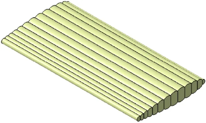
Fig. 3. Baffled inflatable wing.
For thenth cavity of the inflatable wing shown in Fig. 4, equilibrium equations can be established according to the inflated static equilibrium as follows:
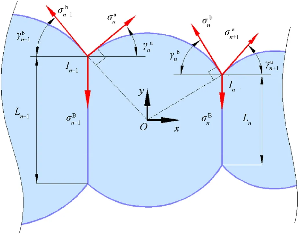
Fig. 4. Force equilibrium of the n th cavity of the inflatable wing.
wherepis the inflation pressure;Lnis the length of thenth baffle;are the normal stresses in the direction of the leading edge and trailing edge on the arc of thenth cavity,respectively;is the angle between the membrane and horizontal axis at the node in the direction of the leading edge and trailing edge of thenth cavity.
According to the nodal force equilibrium [7]:
For a 2D airfoil withNcavities under aerodynamic loads, the following equilibrium is satisfied in the direction of lift.
whereLis the lift;α is the angle of attack(AOA);are the nodal force components at the upper and lower surface,respectively.
For a single-layer plate-shaped inflatable membrane structure resembling an inflatable wing with a shape preserving ability, the existence of sections in the main bearing direction whose shape satisfies the bubble principle should be ensured.Thus,at least one section that is composed of straight baffles and surface arcs are required to ensure the shape preserving ability.
2.2. Design of the swept baffled type
Abstracting from the structural geometry of the baffled inflatable wing,the inflatable beam can be regarded as the basic bearing element of the inflatable wing [10], which is arranged and connected according to certain rules to satisfy the restriction of an airfoil. Therefore, the stiffness distribution and geometric characteristics of the inflatable wing can be changed by rearranging the inflatable beams.An effect closed to an aeroelastic tailoring design will be formed under the rearrangement,and the aerodynamic and aeroelastic characteristics of the inflatable wing will be changed accordingly.For a swept baffled rectangular inflatable wing,whose geometrical parameters and airfoil have been determined, the design procedure is shown in Fig. 5 and can be divided into the following steps.
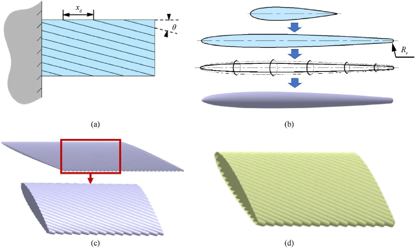
Fig. 5. Design procedure of the swept baffled inflatable wing.
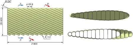
Fig. 6. Sections of the swept baffled inflatable wing with θ = 24?.
(1) Initial selection of design variables.The main variables of the swept baffled inflatable wing are the baffles sweep angle of the inflatable beams θ and the spanwise distance between two adjacent beamsxd.
(2) Formation of the inflatable beam. The chord length of the target airfoil can be stretched as a ratio ofrb, which can be determined as follows.
After the trailing edge of the stretched airfoil is rounded, a complete inflatable beam can be formed by enveloping the normal circular section of the middle arc.
(3) Formation of the effective wing segment. According to the previously selectedxdvalue,the inflatable beams are linearly arrayed in the spanwise direction. The effective wing segment can be intercepted, and the surface of the wing segment can be extracted as the skin.
(4) Formation of the tip and baffles. After projecting the intersecting line between the inflatable beams to the wing plane,a baffle can be formed by filling in the region between the projected and intersecting lines. Then, the wingtip can be formed by filling in the region between the skin and baffle edges.
According to the above design procedure, a series of swept inflatable wings with 13 cross-section inflatable beams,800 mm in span and 400 mm in chord,are designed.The range of θ is limited by the primary load bearing capability of the inflatable wing.Considering the integrity of the bearing element, at least one inflatable beam is required to be ensured to extend from root to tip.In conjunction with other geometric parameters of the prototypes,the boundary of θ is approximately±24?.The rounding radiusRris selected as 12 mm,andxis selected as 59.8 mm to ensure that the rounding of the trailing edge is tangent in the prototypes. These prototypes with critical θ will be used as the basis of subsequent research in this study. A geometric comparison shows that the inflatable wings with symmetrical or asymmetrical airfoils can be effectively designed by the method. Because of the swept arrangement of the inflatable beams,sections satisfying the bubble principle will form an angle with the chord direction, as shown section B-B in Fig.6.Sections of the chordwise inflatable beams are chamfered into ellipses,and the ripples are smoothed,as shown in Fig. 7. Therefore, the swept baffled type achieves a better approximation effect to the target airfoil than that of the baffle type under the same number of inflatable beams, which can effectively improve the aerodynamic performance.
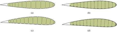
Fig. 7. Airfoil comparison of the inflatable wings.Note that two traditional configurations of inflatable wings can also be designed by the above design procedure. When θ = 0?, the inflatable beam is a uniform cylinder with an infinite length,which corresponds to a traditional baffled type.When θ =90?,a chordwise baffled inflatable wing will be obtained,as shown in Fig.8.The chordwise baffled type has a smoother chordwise profile and a predictable ideal aerodynamic performance before stalling. Because of the complete loss of spanwise support, the aerodynamic load is balanced by the tension provided by the distributed suspension cables.Therefore,the chordwise baffled type is mainly used for aircraft with low speed and load requirements,such as parasols or paragliders, which are not considered in present study.
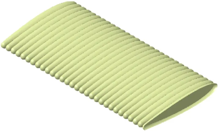
Fig. 8. Designed inflatable wings with θ = 90?.
2.3. Shape preserving performance and aerodynamic performance
To verify the shape preserving ability of the designed swept baffled inflatable wing, prototypes of the swept baffled type and traditional baffled type are manufactured with the same membrane material and design parameters as the simulation model. The VSTARS dual camera system based on the digital image correlation(DIC) method is used for testing. The process is shown in Fig. 9.Orientation of the test system is completed by photographing and calculating the 3D-coordinate information of spatially coded mark points at first. The measurement mark points are pasted on inflatable wings to capture and process the 3D-coordinate information of feature mark points.The V-STARS dual camera system is used to process the 3D-coordinate information of the measurement mark point set. A comparison between the marking points on the inflatable wings and target airfoil is shown in Fig.10.The geometric root-mean-square errors (RMES) between the inflatable wing and target airfoil are compared, and the results show that the swept baffled inflatable wing has better shape preserving ability.
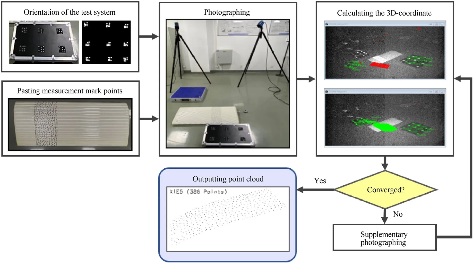
Fig. 9. The process of shape preserving test.
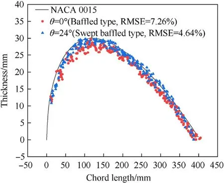
Fig.10. Scatter plot comparison of inflatable wings.
Studies on the aerodynamic characteristics of baffled inflatable wings show that the rippled surface will increase drag with delayed separation at a low Reynolds number [27]. Compared with the baffled type, ripples of the swept baffled type are smooth and extended spanwise obliquely. To verify the aerodynamic characteristics of the swept baffled inflatable wing, the steady flow field with different AOAs was solved by the CFD method based on the Reynolds averaged N—S (RANS) equation. The computational simulations are performed by ANSYS/Fluent.To ensure the reliability of the solution,the turbulence model is selected as SSTk—ω[27],and the upwind scheme is set to the second order based on reference to previous research.The size of the flow field is set to 12.5 times the characteristic size of inflatable wings.An unstructured mesh of the order of 5 million is adopted and locally densified near the wing surface, as shown in Fig.11. The boundary condition is set as the pressure far field, and the velocity of the incoming flow is set as 100 km/h (Ma0.082).
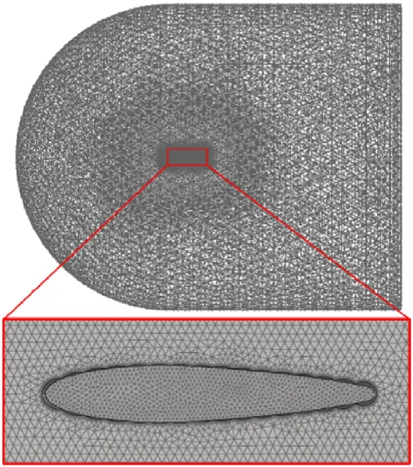
Fig.11. Flow field model of inflatable wing.

Fig.12. Comparation of the lift coefficient.
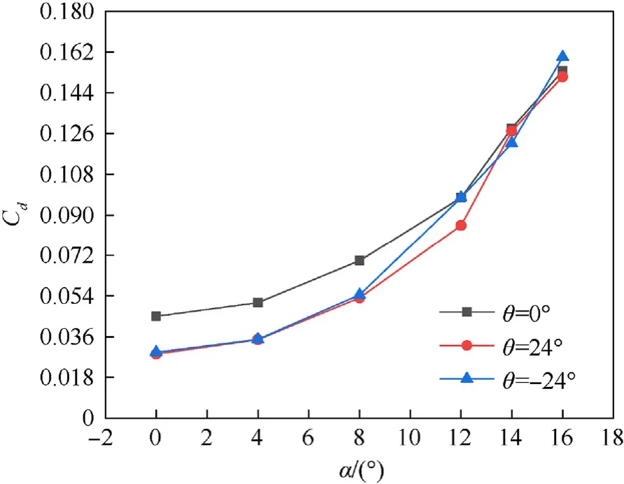
Fig.13. Comparation of the drag coefficient.
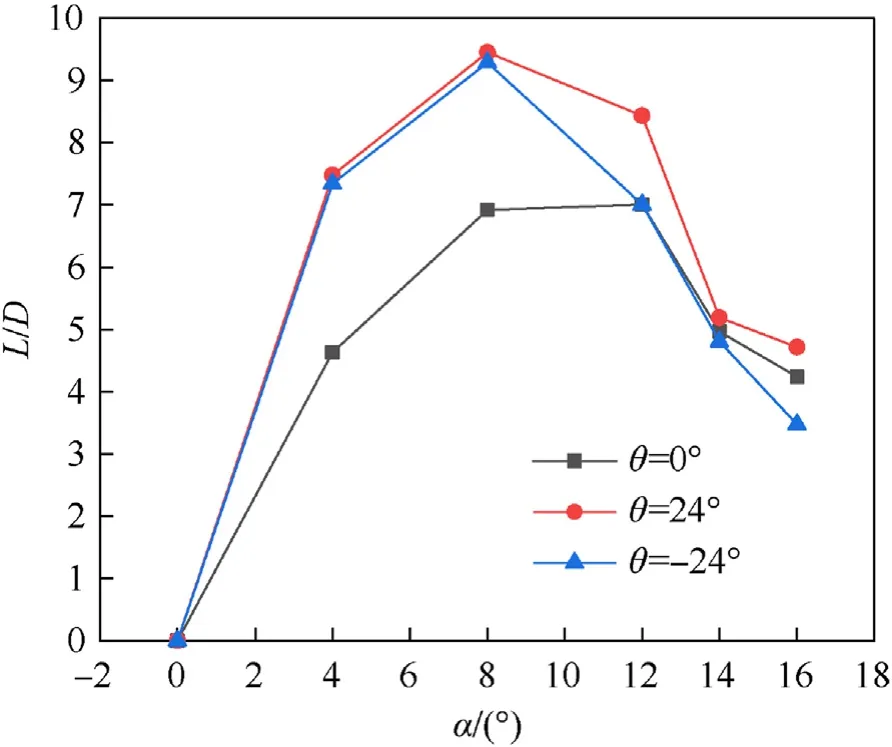
Fig.14. Comparation of the lift drag ratio.
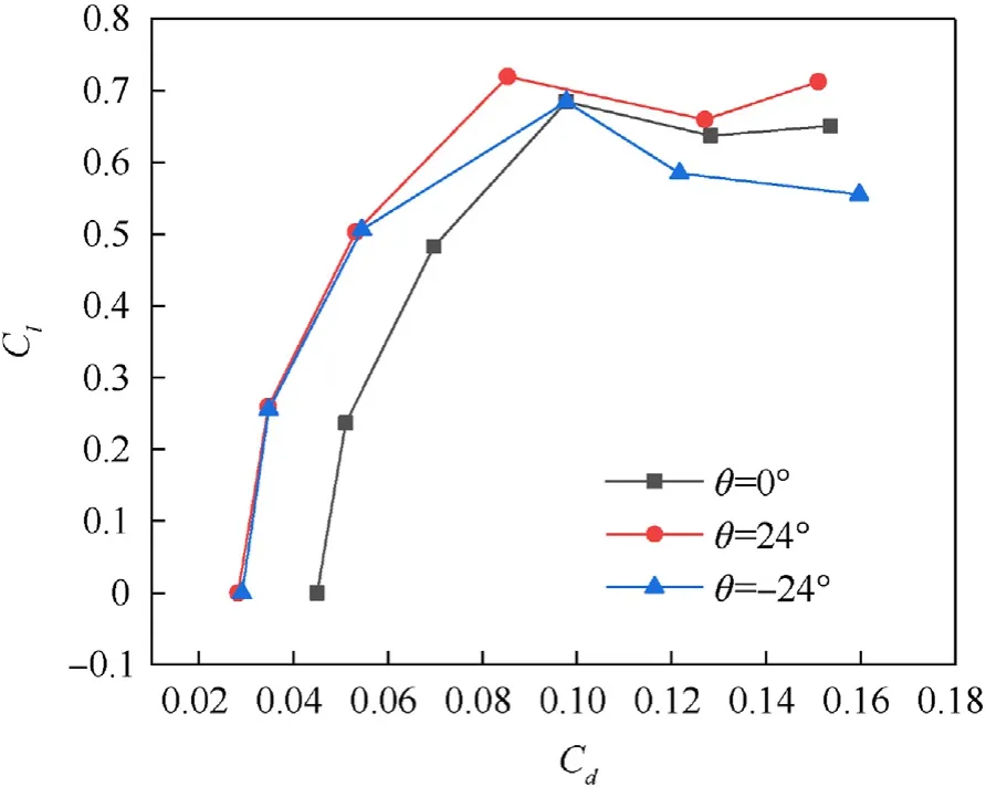
Fig.15. Comparation of the A-curve.
Comparisons of the aerodynamic coefficient,lift drag ratio,and A-curve of inflatable wings under different angles of attack are shown from Figure 12—15, and listed in Table 1. For the lift drag ratio, the swept baffled types achieve an approximate increase before stalling compared with the baffled type. For the backward swept baffled type with θ= 24?, the trend of the lift coefficient is consistent with the baffled type, while a higher lift drag ratio is achieved after stalling.For the forward swept baffled type with θ=- 24?, there is a more severe lift loss and drag cost after stalling.
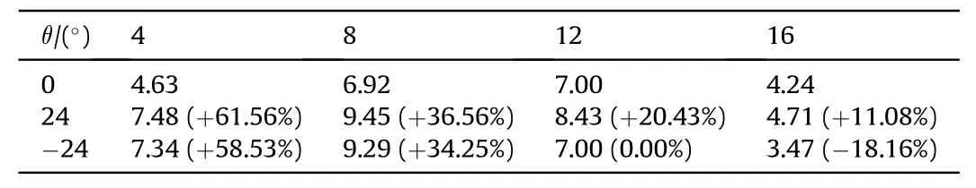
Table 1Comparation of lift drag ratio.
3. Wet modal modeling
The structural dynamic parameters of inflatable wings need to be accurately analyzed as the input of aeroelastic analysis.Focus on the structural characteristics of inflatable wings and the shortcomings of existing methods, an additional mass-stiffness method is developed in this paper. Based on the added mass method, the proposed method fully considers the spatial distribution and stiffness contribution of fluid, and achieves both accuracy and efficiency. The basic principle is briefly introduced as follows.
3.1. Pre-stressed membrane theory
For inflatable structures,the membrane balances the out-plane load with the in-plane tension, which is mainly provided by the pressure difference between the internal pressure of the inflation and the external pressure of the atmosphere.Assume that the prestressed membrane is isotropic, and the thickness ish, the equilibrium equation of the pre-stressed membrane element is shown as follows:
whereTx,Tyis the in-plane tension of membrane element in the direction ofxandy,pis the pressure.Tx,Tycan be expressed as follows:
whereEmis the Youngs' modulus of the membrane material.
The statics equilibrium equation of the pre-stressed membrane structure can be obtained with Eqs. (10) and (9).
When the pre-stressed membrane structure vibrates freely,the shape of the membrane with inflation and deformation is taken as the reference configuration. Assume that the plane namedxoyis consistent with the plane where the membrane deforms, and the vibration displacement , which is vertical to thexoyplane, is considered as minim, thus the tension change caused by vibration can be ignored.As shown in Fig.16,the motion differential equation of pre-stressed membrane structure when vibrates freely can be expressed as follows:
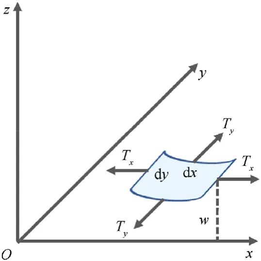
Fig.16. Vibration of the pre-stressed membrane structure [28].
where ρ is the surface density of the pre-stressed membrane element dxdy,TxandTyis the membrane tension of membrane element.
3.2. Wet modal modeling based on added mass-stiffness method
Because of the lightweight of the inflatable wing structure,ambient air occupies an indispensable proportion of mass in the vibration system, and the added mass effect should be taken into consideration [29,30]. Therefore, a dynamic characteristic analysis should be conducted considering the influence of the flow field on the inflatable wing. This is referred to as a wet modal analysis.Existing wet modal analysis methods mainly include the FSI method and added mass method[31].In FSI method,the flow field is treated as the acoustic field,and an asymmetric solver is adopted[20]. Under the acoustic pressure energy diffusion effect, the accuracy of the FSI method is determined by geometry scale of flow field,which leads to an imbalance between cost and accuracy[23].The added mass method simplifies the flow field to mass nodes distributed on the surface of the structure, which has the advantages of a high efficiency and accuracy [31]. However, the contribution of the flow field to the system stiffness is ignored,resulting in an insufficient description of the wet mode mechanism.
Focusing on the inflatable wing, a wet modal analysis method based on the added mass method and further considering the contribution of the flow field to the system stiffness is adapted,which is named as the added mass stiffness method here. The external added mass of slender structurecan be expressed as follows [32]:
whereBis the width of the structure,dis the average draft,andMVis displacing. For the inflatable membrane structure, the internal pressured gas vibrates with the structure,and masscan be expressed as follows:
where ρflu(p)is the density function about the pressure of the fluid;Vis the volume of the pressured gas. The fluid added mass of inflatable membrane structureMaddedcan be expressed as follows.
The shape function of the flow field is determined according to the principle of the average. The volume of flow fieldVfcan be expressed as the following.
According to the principle of average, the flow field is determined based on the structural geometry or boundary conditions.The shape function of flow fieldNfcan be expressed as follows:
whereNsis the shape function of the inflatable structures,n is the normal vector of the inflatable structure shape function and Δxis the distance between the inner and outer boundary of the flow field.
The shape function of the flow field is the same as that of the inflatable structure at the inner boundary.Therefore,the flow field shares nodes with the inflatable structure at the inner boundary.The shape function of the flow field at the outer boundary is determined according to the distance between the inner and outer boundary evenly. For the constrained boundary,the flow field and inflatable structure are fixed because of the absence of vibration.
For homogeneous fluids, the form of the governing equation in micelle is similar to that of a solid [33]. Air is able to resist stress owing to compressibility and viscosity, while vibrating accompanied by the inflatable structure [34]. According to the relationship between the elastic coefficients of isotropic materials,an equivalent modulus of air under a small disturbance can be expressed as follows [35]:
whereKis the bulk modulus.The equivalent model of the flow field can be obtained based on Eqs.(15)—(18)and the contribution of the flow field to system stiffnessKaddedcan be expressed as follows:whereIfis the inertia of the flow field.
3.3. The validation of an inflatable tube
In order to verify the accuracy of the established model, the inflatable ethylene-terafluoroethlene (EFTE) tube is selected as an example to be verified,and compared with the experiment results.The geometric, material parameters and boundary conditions are consistent with previous studies[23].The finite element(FE)model established by added mass stiffness method in this paper is shown in Fig.17,the comparison with other wet modal analysis method is listed in Table 2, and the modal shapes are shown in Fig.18.
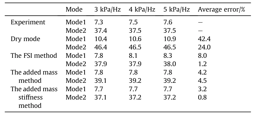
Table 2Natural frequencies comparison of the inflatable beam.
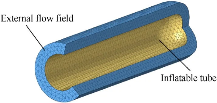
Fig.17. The FE model of the inflatable beam based on added mass-stiffness method.
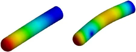
Fig.18. Mode shapes of the inflatable beam.
According to the results shown in Table 2, there exist a significant difference between dry mode and wet mode,which proves the necessity of wet modal analysis.Because there is no need to adopt the asymmetric solver, compared with the FSI method, the efficiency of added mass stiffness method is significantly improved.While compared with the traditional added mass method[36],the contribution of the flow field to the system stiffness is well considered, which improves the estimation performance for the natural frequencies of inflatable structures. For the validation example in this paper, the relative error of first two natural frequencies between experiment results and the simulation results based on the added-mass stiffness method is 3.2%and 0.8%,which is able to satisfy the accuracy need for the wet modal analysis of inflatable wings.
4. Wet modal analysis and experimental verification
4.1. Modeling
To further verify the accuracy of the proposed added massstiffness method, the modal experiments of the inflatable wings are conducted. The modal experiment system is set up shown as Fig.19, including 4 parts, which are the inflatable wing structure,the force and acceleration sensors, the measurement and analysis system,and the pedestal.The modal experiment image is shown as Fig. 20.
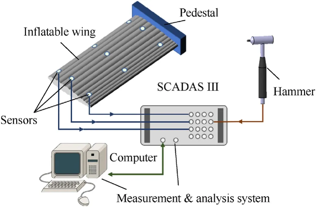
Fig.19. Vibration experimental system of the inflatable wing.
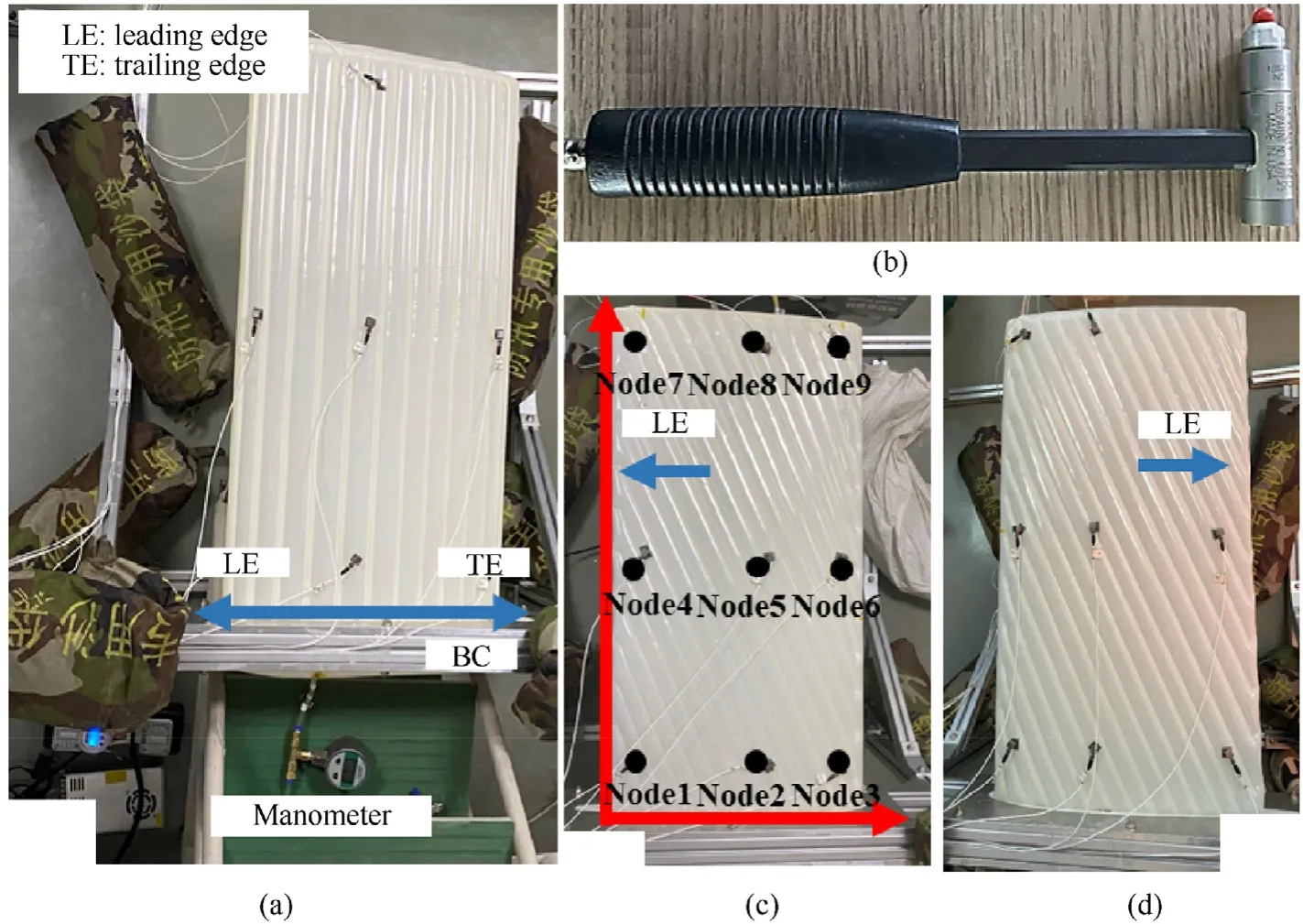
Fig. 20. Modal experimental image of the inflatable wing.
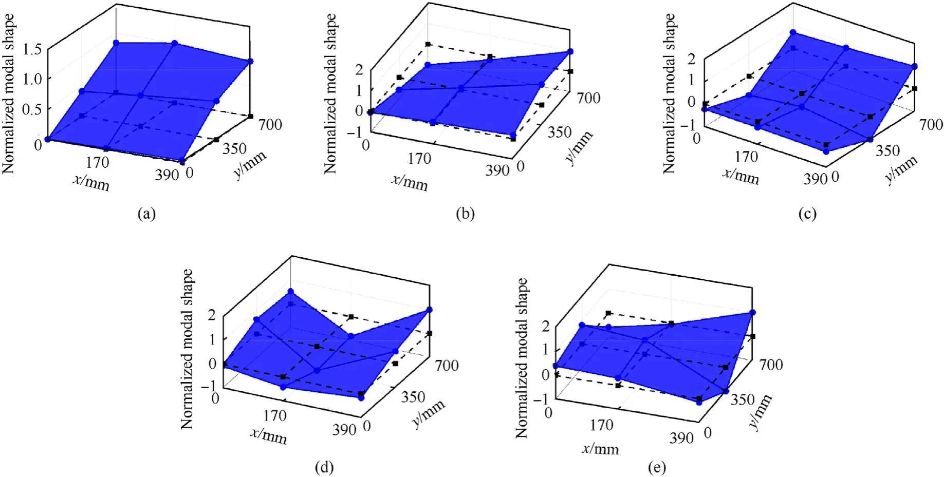
Fig. 21. Modal experimental results of the inflatable wing with θ = 0?.
As shown in Fig.22,the baffles sweep angles θ of three inflatable wings tested in this paper is 0?in Fig.22(a),-24?in Fig.22(c),and 24?in Fig. 22(d) respectively. The geometry parameters of the inflatable wings are the same as the ones designed in subsection 2.2, where the airfoil is NACA0015, chord length is 400 mm, span length is 800 mm, and the number of cross-section inflatable beams is 13. All three inflatable wings are made of high strength composite flexible membrane material, and the material parameters are shown in Table 3. The flexible fiber composite material is orthotropic material, and the mechanical property difference between warp and weft is not remarkable. For the sake of engineering estimating, the membrane is considered isotropic[37—39]. Besides, the inflation pressure is set as 30 KPa. The pedestal structure is made of the aluminum profile and sandbags,where the inflatable wing is able to be fixed at one end while free at the other. The environment parameter of the modal experiment is(25 ± 3)?C, and the relative humidity is 50%.

Table 3Material parameters of the inflatable membrane.
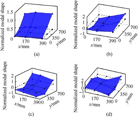
Fig. 22. Modal experimental results of the inflatable wing with θ = - 24?.
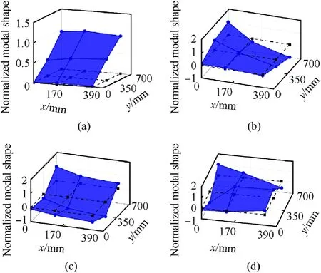
Fig. 23. Modal experimental results of the inflatable wing with θ = 24?.
As shown in Fig.20(b),the hammer chosen in this paper is PCB 086C03,and the air capsule hammerhead is adapted to improve the effect of excitation for flexible inflatable wings [40]. The force and acceleration sensors are used to measure the excitation and response signal of the tested structure.As shown in Fig.20(a),nine accelerometer named PCBTM 333B30 are placed evenly on and under the inflatable wing surface, and the excitation point is selected as the node near the trailing edge at the tip of the inflatable wing, which is node 9 for the inflatable wings with θ equaling 0?and 24?, and node 7 when θ = - 24?.The measurement and analysis system is LMS Test. Lab SCADS III, which is used to define the sampling frequency and sampling time, and process the force and acceleration signal measured from sensors. The sampling frequency is set as 512 Hz,and the sampling time is 8 s. To eliminate the measurement error as much as possible, each test is repeated and averaged for 5 times under certain pressure. The averaged frequency response function(FRF)is identified with poly-reference least squares complex frequency method (PolyMAX). The tests results are shown as Fig. 21, Figs. 22 and 23 which provides the reference for simulation of inflatable wings.
For the inflatable wing with θ = 0?, also known as the traditional baffled inflatable wing, the first five modes with distinct modal shapes are got under 100 Hz,which include the 1st bending,1st torsion, 2nd bending,1st chordwise bending, and 2nd torsion.Among the five modes,the 1st chordwise bending mode is a unique modal shape of the inflatable wings compared with the rigid wings,which will participate in the flutter [28]. Meanwhile, for the inflatable wings with θ=±24?under the same bandwidth, there are only four modes and the eliminated one is the 1st chordwise bending mode, which will help with the flutter performance.
4.2. Wet mode analysis and discussion of factors of the inflatable wings
Based on the added mass stiffness method, a simulation of inflatable wings with different θ are performed by a comparative analysis. The FE model is shown as Fig. 24. Considering the influence of external and internal flow field, the internal flow field is discounted to the external flow field to simply the modeling process, and the volume of external flow field is obtained by Eq. (16).The inflatable wing is modeled with Shell181 element and is fixed at one end.Different from the FSI method,the added-mass stiffness method is able to save the computing cost for only considering the local flow field participate in vibration. Compared with the traditional added-mass method, the proposed method shows the advantage in efficiency and accuracy of estimating the dynamic characteristic of the inflatable structures. The simulation results identified with Lanczos method are listed in Table 4 and shown in Figs.25-27.The inflation pressure is set as 30 kPa,which is the same as the one in modal experiment and suitable enough to make sure the membrane is completely tensioned.
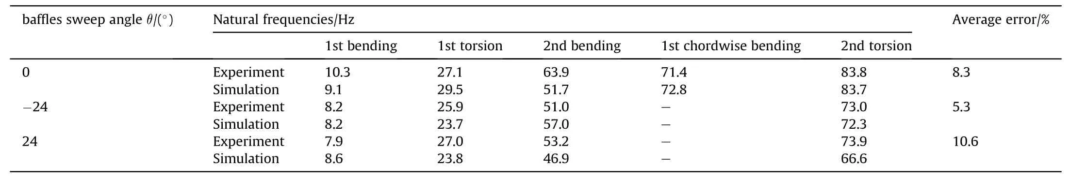
Table 4Natural frequencies comparison of the inflatable wings.
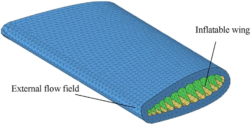
Fig. 24. The FE model of the inflatable wing based on added mass-stiffness method.
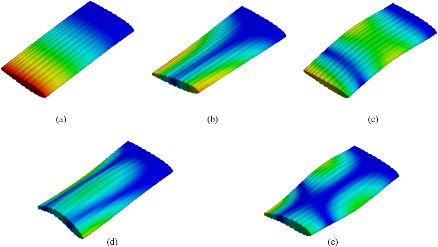
Fig. 25. Simulation results of the inflatable wing with θ= 0?.
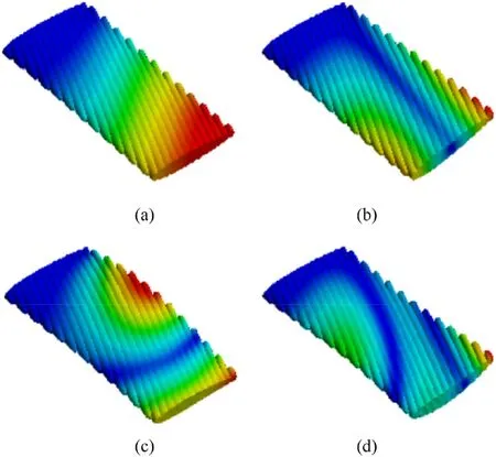
Fig. 26. Simulation results of the inflatable wing with θ= - 24?.
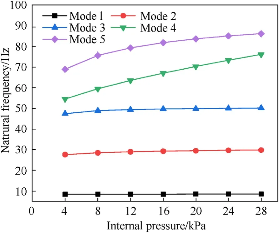
Fig. 28. Natural frequencies of the inflatable wing under various internal pressure.
The simulation results of the inflatable wing with θ=0?reflect five modes,the 1st bending,1st torsion,2nd bending,1st chordwise bending,and 2nd torsion,which shows the same tendency with the modal experiment results.For the swept inflatable wings with θ =±24?,there are some changes in natural frequencies resulted from the deflection of stiffness axis, and the 1st chordwise bending is also eliminated,due to the exist of the baffles sweep angle θ,which means the baffles inside the inflatable wings are able to provide the structural support both spanwise and chordwise.The average error shown in Table 4 indicated the consistency of the natural frequency between the simulation and experiment results, which proves the effectiveness of the proposed method. The averaged error of the inflatable wings with θ=0?and θ=-24?is 8.3% and 5.3%, which are all under 10%and proves the accuracy of the proposed method.For the inflatable wing with θ =24?,the natural frequency is lower due to the process limitation of the tested inflatable wing. The manometer is hung at the free end,and despite the slinging of the elastic rope, the mass of vibration system increases inevitably.Generally, the proposed method is precise enough to estimate the dynamic characteristics of the inflatable wings.The ratio of the first bending frequency to the torsional frequency of the swept baffled type is higher than that of the baffled type, which is beneficial for increasing the flutter critical speed according to Pines’theory[41].Based on the conclusions above,the swept configuration may affect the flutter characteristics of the inflatable wings.
The swept baffled inflatable wings should be fully inflated to maintain the system stiffness and resist bulking. Therefore, the influence of internal pressure should be analyzed. The specific effect of baffles sweep angle on dynamic characteristics of inflatable wings is still unclear and worth discussing.Besides,for aircraft with twin-boom configuration, the horizontal tail is fixed at both ends and has special boundary conditions. Therefore, the influence of boundary conditions of inflatable wing on the structural dynamic characteristics should be deeply analyzed as well.
4.2.1. Effect of internal pressure
For the models with various internal pressure, the inflatable wing with θ=0?is selected and the pressure is set from 4 to 28 kPa.The inflatable wing shows five modes under 100 Hz according to the simulation results are shown as Fig.28,which is consistent with the experiment and simulation results above. All natural frequencies show an upward tendency due to the increasing structure stiffness as the internal pressure rises,and the growth tendency is also slowing down, which is more obvious for the high order modes.For inflatable wings,the stiffness distribution of structure is settled when the internal pressure is enough to fully tension the membrane structure. There will not be distinctive changes of the natural frequencies when the internal pressure increases further.Based on the experiment and simulation results, the reference pressure for the inflatable wing in this paper is 30 kPa, which is proper for both simulation and experiments.
4.2.2. Effect of baffles sweep angle
The swept angel θ is assumed positive for the sweptback wings.According to the definition, it's the traditional baffled inflatable wing when θ = 0°. In the progress of modeling, at least one inflatable beam should extend form the root to tip, which guarantees the ability for inflatable wings to resist bulking. Hence,there is an upper limit for the baffles sweep angle according to the aspect ratio and number of cross-section inflatable beams. The simulation for inflatable wings with various baffles sweep angles is performed and the results are shown as Fig. 29. The internal pressure is set as 30 kPa,and the geometry and material parameters are same as the ones above.
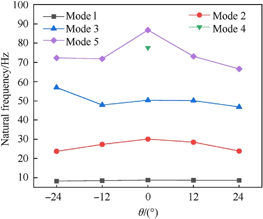
Fig. 29. Natural frequencies of the inflatable wing with various baffles sweep angle θ.

Fig. 30. Simulation results of the inflatable wing with θ= 0?.

Fig. 31. Simulation results of the inflatable wing with θ = ±24?.
Under 100Hz, five modes are obtained for the inflatable wing with θ = 0°, while only four modes for other configurations with nonzero baffles sweep angle θ.The eliminated mode is 1st bending chordwise, which is consistent with the experiment results above.Generally,the natural frequencies show an upward tendency as the absolute value of baffles sweep angle θ decreases. The length of main bearing inflatable beam for the configuration with nonzero baffles sweep angle is larger than the one with θ = 0°. Due to the exist of swept angel θ,the inflatable beams have been participated in circumferential bearing. The membrane structure is barely able to withstand the out-plane load,and thus the stiffness distribution is changed and the equivalent stiffness is also decreased, and results in the decrease of the natural frequencies. Specially, the natural frequency of Mode3 for inflatable wing with θ=-24°is anomalous, and the average error for Mode3 is unsatisfactory.Compared with other order modes. In the modeling process for swept inflatable wings, the intercepted is performed based on the length of the wingspan,there is still the uncertainty of the relative location to cut off, which considers as the reason of unsatisfactory averaged error for Mode3, the 2nd bending.
4.2.3. Effect of boundary condition
The internal pressure is set as 30 kPa, and the inflatable wings with θ=0 and θ=±24°are selected. Based on the one end fixed,the boundary condition of two end fixed is also performed,and the results are shown as Figs. 30 and 31.
Figs. 30 and 31 shows the first five order modal parameters of the inflatable wing with θ=0°and θ=±24°when fixed at two ends. Generally, the natural frequencies of the models with two ends fixed are larger than the ones with one end fixed. For the inflatable wing with θ = 0°, the modal shape is symmetric due to the symmetric configuration. And compared with the inflatable wing with one end fixed,which can be considered to be a cantilever plate, the bending deformation chordwise is obtained for Mode1 and Mode4 in addition to the bending and torsion deformation spanwise.For the inflatable wing with θ =±24°,the modal shape is unsymmetrical because of the swept angle.
5. Analysis of the aeroelasticity performance
5.1. Flutter modeling
For the segment of the inflatable wing shown in Fig. 32, the governing equations can be expressed as follows [36]:
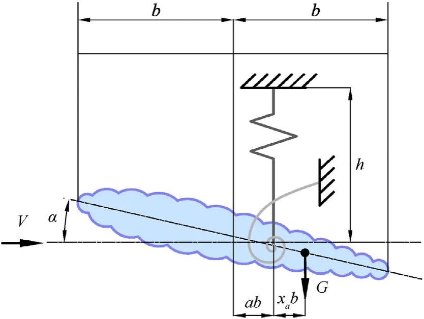
Fig. 32. Motion model of the inflatable wing segment.
wheremis the mass of the segment;his the deflection at the elastic axis of the segment;Sα is the static moment of the segment;KhandKαare the bending and torsional stiffness of the segment, respectively;Iα is the inertia of the elastic axis section;Mis the aerodynamic moment.The wing is assumed to vibrate harmonically at the flutter critical speed. The generalized displacement can be expressed as follows:
For inflatable wings suitable for low-speed flight, the flutter determinant can be obtained simultaneously with Eqs. (22) and(23).
where ωαand ωhare the natural frequencies corresponding to the bending and torsion mode, respectively;xα is the length between the center of gravity and elastic axis;rαis the radius of gyration of the elastic axis;ais the length between the elastic axis and half chord;xα andacan be expressed as follows:
wherexGis the chordwise coordinate of the center of gravity.
All elements excepta11will be affected by the center of rigidity distribution in the flutter determinant. Because the flutter critical velocity is determined by eigenvalues of the corresponding coefficient matrix of the flutter determinant, the center of rigidity distribution will affect the velocity critical flutter.Based on the theory mentioned above,the flutter critical velocity of the inflatable wing is analyzed by the V-g method.The structural damping coefficientgis introduced into the motion equation of the wing in the V-g method,and the sum of the structural damping force and resilience can be expressed as follows:
Substituting Eq. (26) into Eq. (22), the elements of the flutter determinant are transformed into the following:
An intermediate variableZis introduced,as shown in Eq.(28);gcan be expressed in the form of Eq.(29).Flutter frequency ω can be obtained by solving the flutter determinant wheng=0 [41].
5.2. Discussion of the baffles sweep angle for aeroelastic performance
By definition,loading on the elastic axis will not twist the wing.A simple static simulation is repeated to determine the location of the elastic axis, as shown in Fig. 33. The center of gravity can be directly obtained through computer aided design (CAD) software and the center of pressure is assumed to be a quarter of the chord length from the leading edge in low-speed flight. The relevant parameters of the inflatable wings are listed in Table 5,according to previous research on the flutter analysis of an inflatable wing with similar geometric parameters [36]. The Theodorsen theory is selected as an unsteady aerodynamic model, while natural frequencies and modal shapes functions of the wet modal are used as the structural discipline input;gis taken as 0 to obtain a conservative value[42].The flutter critical speed and V-g graphs are listed in Table 6 and shown in Fig. 34, respectively.
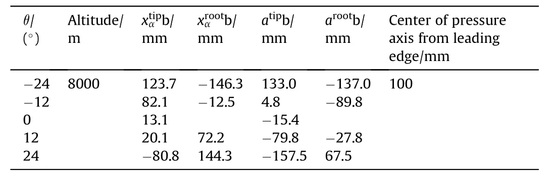
Table 5Flutter model parameters of the inflatable wing.
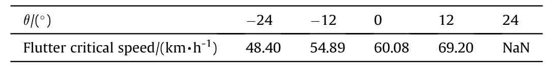
Table 6Flutter critical speed comparison of the inflatable wing.
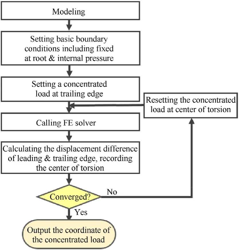
Fig. 33. Calculation process of elastic axis distribution.
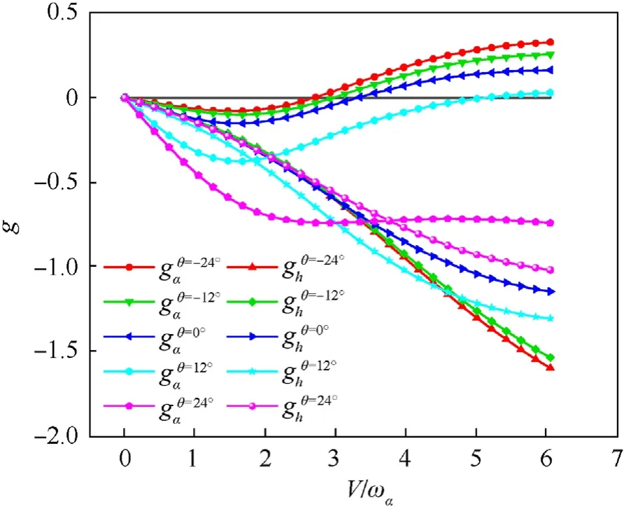
Fig. 34. Comparison V-g graphs of the inflatable wings.
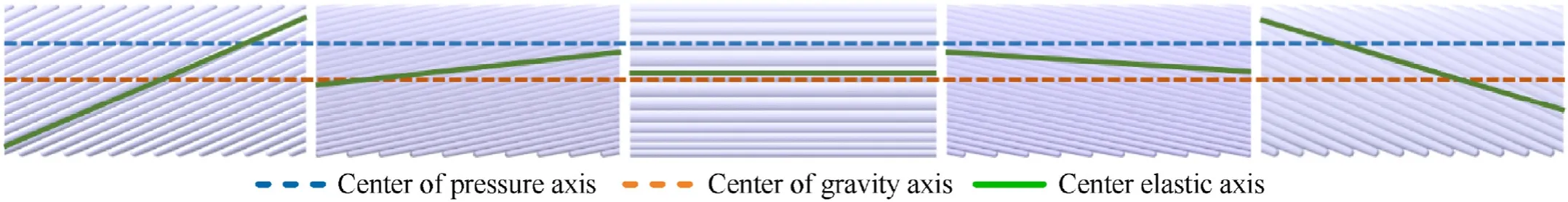
Fig. 35. Elastic axis distribution of the inflatable wing.
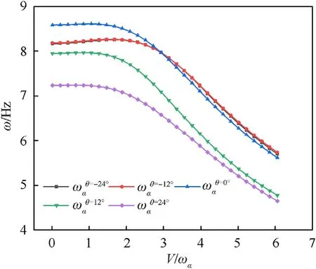
Fig. 36. Comparison V-ω graphs of the inflatable wings.
The flutter critical velocities of the inflatable wing increase with the increase of the θ,as shown in Table 6 and shown in Fig.34.The main reason is that the swept arrangement of the baffles’ leads to the change of the elastic axis distribution of the inflatable wing.As shown in Fig.35,the elastic axis of the inflatable wing changes with the direction of the baffle,and even cross the center of pressure axis and the center of gravity axis.This will lead to large changes in the aerodynamic term and inertia term in different segments. For the 24?backward swept configuration, the elastic axis is closer to the trailing edge at the wingtip than the center of gravity, thus inhibiting the classical flutter caused by the coupling of low-order modes[42]. For the - 24?forward swept configuration, the elastic axis is closer to the leading edge at the wing tip, which leads to the reduction of the flutter critical speed. At the same angle, both the forward swept and the backward swept configurations will lead to significant changes in the distribution of the elastic axis over the entire wing. Since the mode shape functions increase monotonically in the spanwise, the effect of the sweep angle on the flutter speed can be estimated mainly by the relative position of the elastic axis at the wing tip.
At the same time, the frequencies of torsional modes’ decrease with the increase in speed,and the most obvious decrease is in the 24?swept back configuration, which indicates that it may have a lower divergence speed,as shown in Fig.36.This may also be due to the distribution of the elastic axis, which results in the maximum torque at the wingtip of the swept back configuration under similar aerodynamic loads.Note that with the aerodynamic model selected in this paper, all cases do not have torsional divergence, but this does not mean that inflatable wings are safe at the speed before flutter. For the nonlinear behavior of inflatable wing failure, previous research have given more accurate and specific methods[43].The focus of this paper is to reveal the influence trend of sweep angle on the aeroelastic behavior of inflatable wings, rather than accurately predict the divergence speed.
In general, the contribution of swept back configuration and swept forward configuration to aeroelastic characteristics of inflatable wing is opposite.Flutter and divergence can be inhibited by designing different sweep angles, respectively. This indicates that the proposed structure may be enlightening for the aeroelastic tailoring design of inflatable wings. Considering that the swept baffled type has better aerodynamic performance, the inflatable winged loitering munitions with this structural scheme is expected to achieve higher useable speed.
6. Conclusions
(1) Compared with the traditional baffled inflatable wing, the swept baffled inflatable wing can achieve better approximation and aerodynamic performance to target the airfoil after inflation.The proposed method can effectively provide the geometry of inflatable wings with different baffles sweep angles.
(2) The stiffness of the surrounding fluid will affect the modal parameters of the structure. Therefore, compared with the traditional added mass method, the proposed added mass stiffness method can predict the wet modal parameters of inflatable structures more accurately.
(3) Take the internal pressure, the baffles sweep angle and the boundary condition as effect factors into consideration. The natural frequencies are rising as the internal pressure is increasing, and the absolute value of baffles sweep angle is decreasing. The larger natural frequencies and more chordwise bending modal shapes are obtained for the inflatable wings with both ends fixed.
(4) The aeroelastic characteristics of the inflatable wing vary with the baffles sweep angle. With the increase in baffles sweep angle,the flutter performance of the inflatable wing is improved and the divergence performance is degraded.This conclusion is considered having potential value for aeroelastic tailoring design of inflatable wing.
Declaration of competing interest
The authors declare the following financial interests/personal relationships which may be considered as potential competing interests: The authors declare the following financial interests/personal relationships which may be considered as potential competing interests: Junhui Meng reports financial support was provided by National Natural Science Foundation of China.
Acknowledgements
This research was supported by National Natural Science Foundation of China (Grant No.11902029). The authors thank all the people involved in the past and present progress of the experiment. The authors also are grateful to the reviewer and the executive editor for their precious suggestions about this paper.

- Defence Technology的其它文章
- Defence Technology
- Joint target assignment and power allocation in the netted C-MIMO radar when tracking multi-targets in the presence of self-defense blanket jamming
- Design and dynamic analysis of a scissors hoop-rib truss deployable antenna mechanism
- Cooperative trajectory optimization of UAVs in approaching stage using feedback guidance methods
- An improved four-dimensional variation source term inversion model with observation error regularization
- Research on the distribution characteristics of explosive shock waves at different altitudes