
Comparison of heating mechanisms of argon helicon plasma in different wave modes with and without blue core
2023-03-09 05:45:24RuilinCUI崔瑞林TianliangZHANG張?zhí)炝?/span>QianYUAN袁倩FengHE何鋒RuoyuHAN韓若愚andJitingOUYANG歐陽(yáng)吉庭
Plasma Science and Technology 2023年1期
Ruilin CUI(崔瑞林),Tianliang ZHANG(張?zhí)炝?,Qian YUAN(袁倩),Feng HE(何鋒),Ruoyu HAN(韓若愚)and Jiting OUYANG(歐陽(yáng)吉庭)
School of Physics,Beijing Institute of Technology,Beijing 100081,People’s Republic of China
Abstract In this work,we investigated the discharge characteristics and heating mechanisms of argon helicon plasma in different wave coupled modes with and without blue core.Spatially resolved spectroscopy and emission intensity of argon atom and ion lines were measured via local optical emission spectroscopy,and electron density was measured experimentally by an RFcompensated Langmuir probe.The relation between the emission intensity and the electron density was obtained and the wavenumbers of helicon and‘Trivelpiece-Gould’(TG)waves were calculated by solving the dispersion relation in wave modes.The results show that at least two distinct wave coupled modes appear in argon helicon plasma at increasing RF power,i.e.blue core(or BC)mode with a significant bright core of blue lights and a normal wave(NW)mode without blue core.The emission intensity of atom line 750.5 nm(IArI750.5nm)is related to the electron density and tends to be saturated in wave coupled modes due to the neutral depletion,while the intensity of ion line 480.6 nm(IArII480.6nm)is a function of the electron density and temperature,and increases dramatically as the RF power is increased.Theoretical analysis shows that TG waves are strongly damped at the plasma edge in NW and/or BC modes,while helicon waves are the dominant mechanism of power deposition or central heating of electrons in both modes.The formation of BC column mainly depends on the enhanced central electron heating by helicon waves rather than TG waves since the excitation of TG waves would be suppressed in this special anti-resonance region.
Keywords:argon helicon plasma,wave coupled mode,optical emission spectroscopy,helicon waves,TG waves
1.Introduction
Helicon plasmas have attracted great attention in applications of material processing,surface treatment and electric thrusters due to their high ionization rate and high plasma density[1–4].Most researches in helicon plasma sources have been carried out in a wide range of electron density from 1010to 1014cm?3under relatively low external magnetic fields(0.1 mT–0.1 T)and radio-frequency(RF)power(1–5 kW)[5–8].For ion heating in large linear devices,helicon plasma sources were also studied under higher magnetic fields(0.1–5 T)and higher RF powers(10–100 kW)[9–12].Argon helicon plasma is the most common one investigated in recent years[7–10,13–15].One of the unique characteristics of argon helicon discharge is the mode transition characterized by a significant jump of electron density at increasing RF power or magnetic field,showing at least three fundamental discharge modes,i.e.the capacitively coupled(E)mode,inductively coupled(H)mode and wave coupled(W)mode in various setups[16–21].In some conditions,a centralized blue core(BC)or big blue can be observed in W mode,characterized by an intense column of blue light in radial axis of discharge tube and a dramatic increase in plasma density[21–23].Sometimes,the appearance of BC was also used as an identification of W mode[16,21,23–25],but this is not always correct since it is only one of the wave coupled modes whose characteristics and mechanisms of power absorption are different from the others.
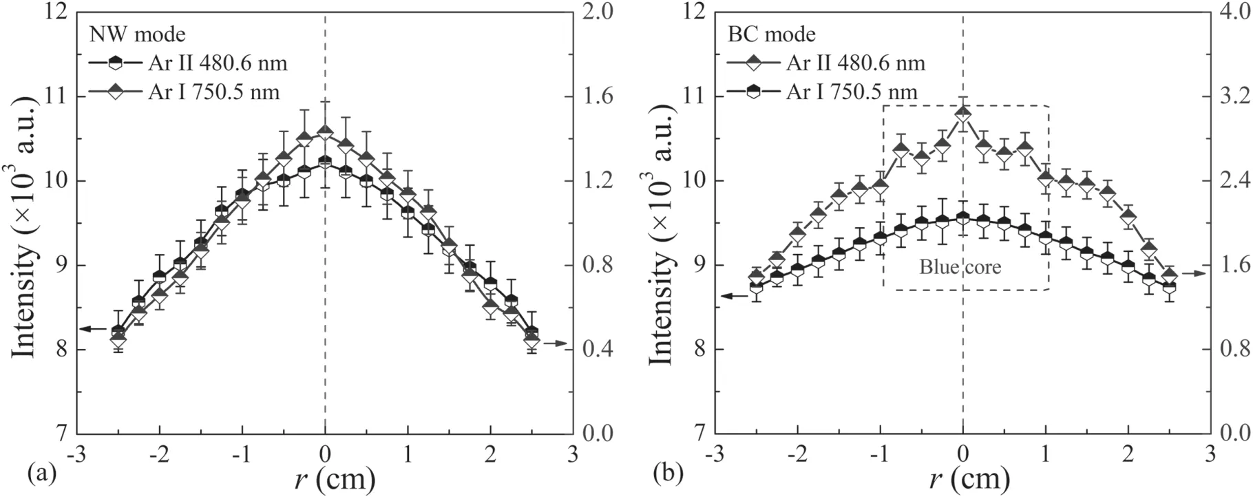
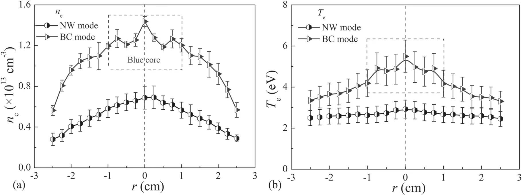
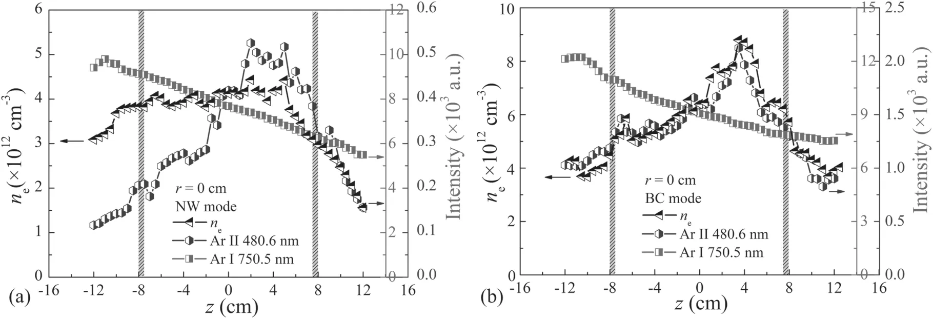
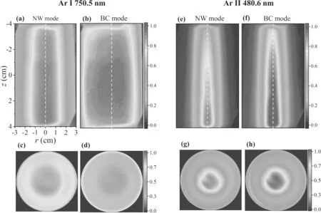
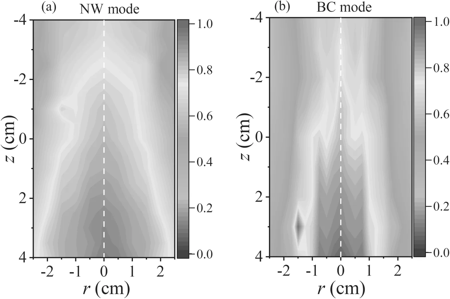
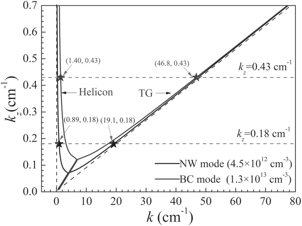
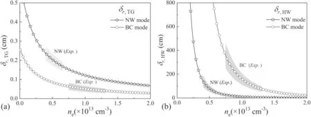
Generally,the wave excited in a helicon plasma source consists of two components,i.e.the weakly damped,bounded whistler or fast ‘helicon’ waves,and the strongly damped,slow or ‘Trivelpiece-Gould’(TG)waves[26–31].The two components provide the power release in different regions of the plasma.TG waves,which satisfy the dispersion relation at low plasma densitynp(np Optical emission spectroscopy(OES)is one of the widely used measures to diagnose the characteristics of helicon plasmas since it is comparatively cheap,versatile and non-intrusive[43,44].OES has advantages of no scan voltage,unaffected by the plasma potential oscillations,magnetic and electric fields than Langmuir probe(LP)[45,46].Most notably,a spatial-resolved local OES(LOES)can be used for space-resolved diagnostic by means of a local fiber-optic probe[13–15].In this way,the high-spatial-resolution profiles of electron density and temperature can be obtained.It was confirmed that the atom line Ar I 750.5 nm can quantitatively characterize the relative electron density since the line Ar I 750.5 nm is generated by electrons directly colliding with ground state particles in helicon plasma[13].But this linear relation between Ar I 750.5 nm and electron density seems to be only valid for lower ionization rate and constant electron temperature,which is not valid for helicon plasma with blue core.Detailed spatial distribution of plasma parameters is essential for qualitative analysis. In this work,we presented the experimental investigation based on LOES and LP together with theoretical analysis,aimed to deeply understand the radiative characteristics and the mechanisms of power absorption in various wave modes of argon helicon plasma. The experimental setup is schematically shown in figure 1(a),which has been used previously[13,15].Briefly,the discharge tube is made of a quartz with diameter of 6 cm and length of 45 cm.One end is connected to a vacuum chamber(50 cm in length and 33 cm in diameter)and the other is sealed by a dielectric plate(polytetrafluoroethylene,PTFE).Two Helmholtz coils with a distance of 10 cm around the source tube are used to create a uniform axial static magnetic field in the antenna region,ranging fromB0=0 to 500 G.The magnetic coils are cooled by water to maintain the stability of the magnetic field during discharge.Figure 1(b)shows the calculated contour of magnetic field intensity,with the averaged field ofB0≈500 G.The distributions of three measured magnetic fields on the central axis are shown in figure 1(c).In the antenna region,the magnetic fieldsB0=100,300 and 500 G are nearly uniform,but decrease greatly away from the antenna.Pure argon is injected into the discharge tube via the gas inlet of the PTFE cap.RF power at 13.56 MHz is coupled to the plasma via a matching box connected to a half-wavelength helical copper antenna of 15.5 cm in length located outside of the quartz tube.The input RF power isPRF=50–2000 W in experiments and the value is read out directly from the RF power supply.The background pressure in the quartz tube and the stainless-steel vacuum chamber is pumped by a turbo-pump to as low as 10?4Pa before argon is filled,with a working pressure ofp0=0.6 Pa in experiments. Figure 1.Schematic of experimental setup(a),the calculated contour of 500 G static magnetic field(b),and the distribution of measured magnetic field(100,300 and 500 G)along the central axis(c). Figure 2.Electron density(magnetic field B0=100,300,500 G)(a)and emission intensity of Ar I 750.5 nm and Ar II 480.6 nm(B0=500 G)(b)at increasing RF power. Figure 3.Emission spectra and CCD images at RF power of(a)1200 W and(b)1500 W.The magnetic field is B0=500 G.The exposure time is 1.0 ms for OES and CCD camera. Plasma parameters are diagnosed by OES via a fourchannel spectrometer AvaSpec-ULS3648.For spatial resolution,LOES has been adopted as did in our previous works[13–15].An RF-compensated Langmuir probe(LP,ALP system,Impedans)is also mounted to calibrate the electron density and temperature.The LP and LOES fiber probes can be moved in radial and axial directions,to measure a twodimensional(2D)profile of plasma parameters inside the tube.To describe conveniently,a cylindrical coordinate is selected with the origin(r=0 cm,z=0 cm)at the center of the antenna,as shown in figure 1(a).The time-integrated images are recorded by a CCD camera(Nikon D5100).A bandpass optical filter with a central wavelength of 750 and/or 480 nm and a half-bandwidth of 10 nm is placed in front of the camera so that the only light from atom or ion emission is collected.The camera lens is fixed to the antenna center or the observation window with a bracket for side- and end-on views.The end-on view of the discharge image is reflected by a flat mirror.For comparison,the discharge images with a filter of given atom or ion emission lines are also recorded.The exposure time is the same for the same discharge conditions.The wave fields(magnitude and phase)are measured by an RF magnetic probe(or B-dot probe)on the central axis along the plasma column(?14 cm Argon helicon plasmas are produced under various conditions.The mode transitions of helicon discharge,spatial profiles of plasma density and temperature are investigated based on the measurements of LOES,CCD images and RFcompensated LP. Typically,argon helicon plasma undergoes three or four discharge modes depending on the external magnetic field at increasing RF power(also seen in the other experiments[13–21]),characterized by an abrupt change in plasma density and OES intensity,as shown in figure 2.The density and light emission are measured at the antenna center(i.e.r=0 cm andz=0 cm). At a higher magnetic field ofB0=500 G,there are three jumps on the curve,exhibiting four distinct stable operating regions.The discharge firstly operates in E mode,and transits to H mode at RF power aroundPRF=500 W.During this transition,the electron density jumps from ~3.1×10¹¹to~1.1×1012cm?3.AtPRF≥1000 W,discharge transits from H mode to W mode,with the electron density jumping from ~2.9×10¹²to ~4.1×1012cm?3.Above 1500 W,a blue core is formed,accompanied by a density jump from~5.6×10¹²to ~7.6×1012cm?3.This wave mode is significantly different from the former one.To distinguish them,we named the wave mode with a blue core as ‘blue bore(or BC)’mode,while that without blue core as‘normal wave(or NW)’ mode.The plasma density generally increases linearly with the RF power in each mode,but with different slopes.For example,the slope is significantly larger in BC mode(with the value of ~1.1×1010cm?3W?1)than in NW mode(with the value of ~3.9×109cm?3W?1)atB0=500 G. At a lower magnetic field(B0=100 and 300 G in figure 2(a)),BC would not appear.This is similar to the previous work[13,15].AtB0=300 G,there exists the H-W transition aroundPRF=950 W.But the electron density in this NW mode is less than 5.6×1012cm?3.AtB0=100 G,E-H-W mode transitions occur,and that the electron density is relatively lower.In fact,there is a critical magnetic field for BC mode to appear,e.g.B0≥350 G in this work. For comparison,the emission intensities of atom line(Ar I 750.5 nm)and ion line(Ar II 480.6 nm)were measured by a spatially resolved LOES at increasing RF power,as shown in figure 2(b).The change of 750.5 nm intensity has the same trend as the electron density in E and H modes.But the intensity tends to be saturated in W(both NW and BC)modes.On the contrary,the intensity of 480.6 nm shows a different changing trend.In E and H modes,its signal is generally weak,but also increases slightly with RF power.Entering W mode,the 480.6 nm intensity increases dramatically,at least five times that of H mode in this work.The changing trend is similar to the electron density at increasing RF power.Clearly,mode transitions from E,H,NW modes to BC mode can be observed from the intensity of 480.6 nm emission as RF power is increased.This indicates that the argon ion emission of 480.6 nm is a good index of the electron density as well as the mode transition of argon helicon discharge. In this section,we focused on the OES characteristics in various wave coupled modes.In all cases,magnetic field isB0=500 G,RF power isPRF=1200 W for NW mode andPRF=1500 W for BC mode. 3.2.1.Spectra in NW and BC modes.Figure 3 shows the comparison of emission spectra(400–900 nm)and timeintegrated images for NW and BC modes. In NW mode(PRF=1200 W,figure 3(a)),the emissions of Ar atom lines(ranging from 600 to 900 nm)are dominant.The discharge image shows a diffuse ‘blue’ column with a pink edge.In BC mode(PRF=1500 W,figure 3(b)),Ar ion emissions(ranging from 400 to 600 nm)increase dramatically,at least three times compared with that in NW mode,while the atom emissions do not change obviously.Clearly,an intense blue column with a diameter of about 2 cm appears. On the other hand,Ar ion emissions are also a label of energetic electrons since the excitation energy is generally higher,Uex≥19.2 eV,while the atom emissions represent total bulk electrons of relatively lower energy because the excitation energy is relatively lower,Uex=13–15 eV.Then the above results also indicate that the energy and density of electrons are increased from the NW mode to the BC mode,thereby enhancing the heating efficiency of electrons through wave–particle interactions. 3.2.2.Radial profile.Figure 4 plots the radial distributions of the emission intensity of Ar atom line(750.5 nm)and Ar ion line(480.6 nm)in NW(1200 W)and BC modes(1500 W).The LOES is measured in the center of the antenna atz=0 cm. Figure 4.Radial profiles(measured at z=0 cm)of relative emission intensity of 750.5 nm and 480.6 nm in radial axis of the antenna in(a)NW and(b)BC modes.The magnetic field is B0=500 G. Figure 5.Radial profiles(measured at z=0 cm)of(a)the ne and(b)the Te in NW and BC modes.The conditions are the same as figure 4. In NW mode,both 750.5 nm and 480.6 nm emissions have a similar‘V-shaped’profile,with maximum intensity in the radial center.In BC mode,only 750.5 nm emission shows the ‘V-shaped’ profile,but the intensity changes not so large(about 8%between the maximum and minimum),indicating a nearly uniform distribution(or flat profile).However,480.6 nm emission has a sharp and distinct change of intensity in the radial profile.There is a clear boundary of ‘blue core’ aroundr=±1 cm in figure 4(b),which is consistent with the plasma image in figure 3(b).The blue core is always accompanied by a large radial gradient(~618 a.u.cm?1)of 480.6 nm emission intensity compared with that in NW mode(~392 a.u.cm?1). Figure 5 shows the radial profiles of electron density(ne)and electron temperature(Te)in the central section of the antenna measured by LP in NW and BC modes under the same conditions as figure 4. Clearly,the electron density has a similar distribution as 750.5 nm and 480.6 nm emissions in NW mode,or a ‘Vshaped’profile.But in BC mode,the profile of electron density is similar to the ion line Ar II 480.6 nm,not the atom line Ar I 750.5 nm.The peak density is about 1.5×1013cm–3,a little higher than that in NW mode(around 6.1×1012cm?3).This is also true for the radial density gradient from the center to the edge,with the value of 5.2×1012cm?3cm?1in BC mode compared with 1.8×1012cm?3cm?1in NW mode.Also,the electron density shows a boundary of ‘blue core’ in profile atr=±1 cm,which is similar to the 480.6 nm emission. The electron temperature has a similar profile as the density(see figure 4(b)).There is also a significant peak(Te~5.5 eV)in the radial center in BC mode.Differently,the temperature is nearly uniform in the radial section in NW mode,with a value aroundTe~2.5 eV.This is also consistent with the other measurements of argon helicon plasmas[17,43,48]. These results of electron density,temperature and 480.6 nm emission reveal that the power deposition and the heating mechanism in BC mode should be different from that in NW mode. 3.2.3.Axial profile.Figure 6 plots the axial distribution of emission intensity(measured by LOES)and electron density(measured by LP)in NW and BC modes.The LOES and LPs were located in the central axis of the discharge tube. Figure 6.Axial profiles(measured at r=0 cm)of electron density ne,emission intensity of Ar I 750.5 nm and Ar II 480.6 nm at the central axis for(a)NW and(b)BC modes.The magnetic field is B0=500 G.The upper and bottom rings of antenna are at z=?8 cm and 8 cm. Figure 7.CCD images of Ar I 750.5 nm(left,(a)–(d))and Ar II 480.6 nm emission(right,(e)–(h)).The upper images are of side-view,and the lower ones are of end-on view.The magnetic field is B0=500 G. Figure 8.2D profiles of spatially resolved Ar II 480.6 nm emission by LOES in(a)NW and(b)BC modes in Ar helicon plasma.The white dash lines mark the radial centre of antenna. In two W modes,the emission intensity of 750.5 nm decreases monotonically from up- to down-stream.The position of intensity peak of 750.5 nm is close to the location of the gas feed(atz=?20 cm).While the intensity of 480.6 nm firstly increases,then decreases,forming a maximum in the lower half of the helical antenna(atz=4 cm). The distribution of electron densitynegenerally has a similar trend as that of 480.6 nm emission in BC mode.The density increases from 5×10¹²to 9×1012cm?3from the upper end of the antenna to the bottom,to form an obvious peak aroundz=4 cm.However,the distribution in NW mode is nearly uniform inside the antenna region,with a density about 4×1012cm?3.A little higher density in the upper half of the antenna in NW mode might be due to the higher gas pressure(near the gas feed positionz=?20 cm).But in BC mode,the neutral density is depleted significantly since the ionization rate is much higher(~70%)than that of NW mode(~9.6%)[14].This dramatic neutral depletion and the very large gradient of neutral density were measured experimentally by Mageeet aland Clarenbachet al[49,50].Recent experiments on the electric propulsion also described the modification of the plasma density profile due to the neutral depletion[51,52].In this case,the density reaches a maximum in the antenna region atz=4 cm(or the lower half of the helical antenna)along the direction of wave propagation. 3.2.4.2D distribution.2D distribution provides a clear picture of electron density and temperature in radial and/or axial direction.Figure 7 shows the time-integrated CCD images of plasma with band-pass filter of 750 nm and 480 nm from side- and end-on views. From NW mode to BC mode,Ar I 750.5 nm and Ar II 480.6 nm emissions do not change significantly in intensity.But 750.5 nm emission becomes more uniform in the measured region in BC mode,while 480.6 nm emission shows stronger intensity and centralized distribution.The core boundary also becomes clearer,corresponding to the large gradient intensity in the radial direction at the edges,which is very similar to the results of Thakuret alat increasing magnetic field[21]. Figure 8 shows the 2D profiles of Ar II 480.6 nm emission(also corresponding to electron density)by LOES in NW and BC modes.The emission intensities are measured in the axial section.The axial range is limited toz=?4 to 4 cm in order to compare with the CCD images in figure 7. Figure 9.Relation between the IArII480.6nm and the in W modes. This 2D map of emission intensity is actually a combination of figures 4 and 6,but is more comprehensive and clearer.In NW mode,there is a centralized peak in any radial cross section alongz-axis(see figure 8(a)).However,it is not exactly the same in the radial direction,showing a maximum in the lower half of the helical antenna.In BC mode,there is an intense localized plasma column with diameter about 2 cm in all the cross sections along thez-axis(see figure 8(b)).The electron density within the column is also not uniform,but has a maximum in the center and in the boundary of the blue core,resulting in a center-peaked radial profile which is similar to figures 4 and 5. From the results above,there are at least two wave coupled modes in the present argon helicon plasma.The characteristics are different from each other. In NW mode without blue core,the emission of atom lines is dominant.The radial distribution of plasma density shows a‘V-shaped’ profile,similar to that of both atom and ion lines.The temperature is nearly uniform in the radial section.The axial profiles of electron density and ion lines are consistent in the lower half of the helical antenna.While in BC mode,the atom lines do not change obviously at increasing RF power,but the ion emissions increase dramatically in intensity.An intense blue core with a diameter of ~2 cm appears.The measuredneby LP andIArII480.6nmby LOES in the radial section and a given axial range all have a much excellent correlation.The atom line intensityIArI750.5nmin radial cross section is nearly flat,with no large variation.However,the gradients of the plasma density and the ion line are considerably large.It indicates that it may be due to the change of power deposition by helicon waves from surface to interior region,to cause the apparent radial gradient in BC mode. In this section,we derive theoretically the relation between OES intensity and electron density as well as temperature,and then calculate the wavenumberskby solving the dispersion relation and compare the heating mechanisms in NW and BC modes. In argon plasma,the atom line Ar I 750.5 nm is one-step excitation which is populated by direct excitation of electronneutral impact from ground state[50].The upper level of the line Ar I 750.5 nm with a radiative lifetime of 24 ns lies 13.5 eV above the ground state.According to the collisionalradiative(CR)model of OES,emission intensityIArI750.5nmin quasi-static equilibrium can be written as whereKArI750.5is a factor with the spectral response of the spectrometer,AArI750.5is the optical emission probability for the transition,τAris the life time of excited state,his the Planck constant,cis the speed of light in vacuum,λ is the wavelength of the transition,neis the electron density,nAris the density of argon ground state particle,is the coefficient rate for electron impact excitation from the ground state which is a function of the electron temperature.Obviously,except the plasma parametersne,nArandthe other coefficients on the right side of equation(1)can be replaced by a constantfor a given emission line. The ion line Ar II 480.6 nm has a shorter lifetime(τ≈7 ns)and much higher excitation energy,i.e.19.2 eV and 35 eV for excitation from the ground state of argon ions(two-step process)and atoms(single-step process),respectively.Since the upper ion level is mainly populated by excitation from the ion ground state Ar+,and both ionization and excitation are proportional to the electron density,the intensityIArII480.6nmis expected to be proportional to the electron densityneand the ion densitynAr+[44,45],or Equations(1)and(3)provide the relation between the emission intensity and the electron density as well as temperature.Indeed,it has been confirmed that a linear relation betweenIArI750.5nmandneis valid for a lower ionization rate(so that the neutral densitynAris nearly constant)and constant electron temperature[13].In this work,the results of OES(which givesIArI750.5nm)and LP(which givesne)in E and H modes are in good agreement and prove again the validity of equation(1)(see figure 2(b)).In this case,argon ion lines(including 480.6 nm)are relatively weak when the discharge has not entered wave mode.Entering W mode(i.e.NW and/or BC),480.6 nm intensityIArII480.6nm,being proportional toaccording to equation(3),increases much faster thanIArI750.5nmat increasing RF power.Actually,IArI750.5nmtends to be saturated according to equation(1)due to the neutral depletion,i.e.lowering of the gas densitynAras the temperature of the neutral atoms increases as well as the ion density(and hence the ion partial pressure)increases when theneandTeincrease dramatically from NW mode to BC mode[14,43,49,50]. To verify this relation,we fitted the experimental data in figure 2(b)by considering the influence of the electron temperatureTe(see section 3.1),obtaining the relation betweenIArII480.6nmand the square root ofTetimes the square ofnein W modes,as shown in fgiure 9.Clearly,a linear relation between theIArII480.6nmand thewas obtained,i.e.as equation(3)of Ar II line can be considered as an approximation function of the square root ofTe[48,53,54],the constantAisFrom figure 9,the constantAis estimated to beA≈324 for BC mode andA≈1300 for NW mode with a standard error of 8%.The difference ofAin the two modes is mainly due to the different electron temperature.The relation between theIArIIand theneas well asTeobtained from the experiment in helicon plasma is consistent with the result of Scimeet al[53]. Generally,in helicon plasma sources,both TG and helicon waves contribute to the plasma heating/production process.Surface and on-axis plasma heating in helicon plasma sources by TG and helicon waves has been observed by many researchers[26–35].In high-density and high-magnetic field discharges,the TG wave is strongly absorbed at the plasma edge(~mm).On the other hand,the weakly damped helicon wave penetrates into the core region where it is absorbed and drives on-axis plasma heating/production.Furthermore,it is well known that the absorption of helicon waves can arise from parametric decay instability,leading to the generation of ion acoustic turbulence,which in turn can heat electrons and/or ions[7,9,10,38–40].But this usually happens at a relatively high magnetic field(saying more than 1000 G),where a lower hybrid frequency approaches pump wave frequency(~13.56 MHz),or in the case of a low magnetic field(20–40 G),parametric decay instability can grow when the helicon wave is propagating near the resonance cone[55,56].In our experiment,the wave frequency is greater than lower hybrid frequency(atB0≤500 G)which suggests that parametric instability might not be the main driving mechanism.From NW mode to BC mode,a center-peaked plasma profile in high-density helicon plasma appears,which implies the power deposition via helicon wave collisional or collisionless processes in the center.To confirm this mechanism,we discussed the power deposition in both NW and BC modes. 4.2.1.Helicon and TG waves in k-space.When the electron inertia is considered,the wave eigenmodes are found to be a combination of helicon and TG waves[26–35].Consider the waves propagating asMaxwell’s equations are written as and the equation of electron motion is The plasma current density is Then equation(6)can be re-written as whereδ=(ω+iν )/ωce,ωce=eB0/me(ν being the total electron collision frequency with ions νe–iand neutrals νm).Using equations(5)and(8)to eliminatej→andE-→,one can obtain Equation(10)can be factored into wherek1andk2are the roots of The rootk1corresponds to the usual helicon waves andk2corresponds to the TG waves.The total wavenumberkhas a component of radial wavenumberkrand axial wavenumberkzwith respect toB0, In helicon plasmas,electron collisions play some roles on the energy deposition.Collisional or collisionless energy damping mechanisms can be employed to explain the observed energy absorption[35,57,58]. 4.2.2.In case of collisionless.We firstly consider the case of collisionless.For that,we set ν=0(orδ =ω /ωce)in equation(12).Then the dispersion relation is or The axial wavenumberkzcan be determined by the axial length of the antenna from power spectrum for them=+1 component of half-helical antenna[46,58–60],or wherelis the axial mode number anddAis the antenna length.Since the parallel and perpendicular components of the wavenumber cannot vary continuously in a bounded system,the density(for fixedB0)in the dispersion relation will not vary in a smooth manner consequently,but must jump when the mode changes[28,61]. In this work,the wave mode transition from NW mode to BC mode is considered to be an axial mode transition which is accompanied by the wavenumber fromkz=π/dAtokz=2π/dA(i.e.the lowest two axial numbers ofl=1 and 2).Putting the antenna lengthdA=15.5 cm into the formula,the wavenumber is estimated to bekz≈0.2 cm?1for NW mode andkz≈0.4 cm?1for BC mode. Figure 10 shows the measured amplitudes and phases of the wave axial components for NW and BC modes along thez-axis.The shaded regions represent the upper and the bottom rings of the antenna.For each mode,helicon waves exist along the entire axial area within the antenna,forming a partially travelling-partially standing wave structure.This is also consistent with the other measurements of argon helicon plasmas[19,61–65].In NW mode,the amplitude of the propagated helicon wave is maximum near the center of the antenna(see figure 10(a))while the amplitude of the propagated helicon wave decays nearly 20% after the first wavelength in BC mode(see figure 10(b)).The wavelength of the helicon wave can be deduced from the measured phase variation(λz=360 /(dφ / dz)).Then the measured wavelengths in the center of the antenna from NW to BC mode are found to change from λz≈33.2–14.5 cm,corresponding to the wavenumber increasing fromkz≈0.18–0.43 cm?1.It is noticeable that the measured values of thekzin NW and BC modes are very close to the theoretical prediction(~0.2 cm?1in NW mode and ~0.4 cm?1in BC mode). Figure 10.Measured amplitude and phase of the wave along the central axis for NW(1200 W)and BC modes(1500 W). Figure 11.Dispersion relation of helicon(left branch)and TG waves(right branch)in kz–k space for NW(black solid line)and BC modes(blue solid line).The axial wavenumbers kz=0.18 cm?1(for NW mode)and kz =0.43 cm?1(for BC mode)are also indicated. Figure 12.The penetrated depths of(a)helicon(δr,HW)and(b)TG waves(δr,TG)as a function of electron density ne.The shaded frames represent the ne ranges for NW and BC modes in experiment,respectively. The helicon-TG wave dispersion obtained from eq uation(14)atB0=500 G(ω ωce≈0.009)is shown in figure 11 for the typical electron density in NW mode ofne=4.5×1012cm–3and in BC mode ofne=1.3×1013cm–3from figure 2(a).Here,the values ofkzare obtained from the above experiments in NW and BC modes. Physically,the total wavenumber of the helicon wave(left branch)is relatively smaller,while that of TG wave(right branch)is larger. In NW mode,the axial wavenumber obtained from the experiment is 0.18 cm?1.For helicon wave,the total wavenumber iskHW=0.89 cm?1.Then the radial wavenumber iskr,HW=0.87 cm?1and the wavelength is λr,HW=7.2 cm.This wave propagates at an angle of θ≈78.4°between k and B0.For TG wave,the total wavenumber iskTG=19.1 cm?1.The radial wavenumber iskr,TG≈kTG=19.1 cm?1and the wavelength is λr,TG=0.33 cm.This wave propagates at an angle of θ≈90°to the magnetic field B0,or the TG wave propagates nearly in the radial direction. In BC mode,the axial wavenumber obtained from the experiment is 0.43 cm?1.For helicon wave,the total wavenumber iskHW=1.40 cm?1.The radial wavenumber iskr,HW=1.32 cm?1and the wavelength is λr,HW=4.7 cm.This wave propagates at an angle of θ≈72.1°between k and B0.For TG wave,the total wavenumber iskTG=46.8 cm?1.The radial wavenumber iskr,TG≈kTG=46.8 cm?1and the wavelength is λr,TG=0.13 cm.This wave propagates at an angle of θ≈90° to B0,or the TG wave in BC mode propagates also nearly in the radial direction. In both NW and BC modes,the TG wave has a largekTG(orkr,TG)and hence a very short radial wavelength(less than 0.33 cm in this work).ThekHWof helicon wave increases from NW mode to BC mode,which is also consistent with higher density operation according to the dispersion relation of helicon wave[4].Generally,the helicon wave should be a standing wave in radial direction[19,66].At the boundary of the plasma column,the wave is reflected,so thatkr,HW·r0=nπ/2(wherer0is the column radius andnis number of half waves).Then the radius of plasma column is inversely proportional to wavenumberkr,HW.When the mode transits from NW to BC,thekr,HWincreases from 0.87 to 1.32 cm?1,hence the radius decreases from 1.8 to 1.2 cm(for the smallest numbern=1),causing the plasma column to shrink. 4.2.3.In case of collision.Although the electron-neutral impact νmin low pressure plasma(e.g.aboutng~4.8×1013cm?3atp0=0.6 Pa in this work)and moderate plasma density(ne~1011–1012cm?3in this work)is low(νm~7.2×10⁶s?1)and not important for efficient Ohmic heating of electrons,the electron-ion collision νe-iincreases significantly in helicon plasma due to the high plasma density,so that the collision damping can still become sufficient.In this case,the wavenumber is a complex,ork=kRe+ikIm.The real part corresponds to the propagation and the imaginary part corresponds to the damping or dissipation of helicon and TG waves. For TG waves,the complex radial wavenumber can be obtained from equation(12),as[27,28] The dissipative part(or radial damping rate κr,TG)is Then we can define the damping depth of TG waves as For helicon waves,the radial damping rate κr,HWcan also be obtained and the damping depth of helicon waves is The depths of helicon waves and TG waves penetrated into the plasma at different electron densities can be calculated accordingly,as shown in figure 12 for NW and BC modes. It is seen that the radial damping depths of helicon and TG waves decrease(or the damping rates increase)with the electron density for NW or BC mode,but with different dropping trends. In NW mode,the damping depth of TG waves decreases gradually with increasing electron density,e.g.δr,TG=0.23 cm decreases to δr,TG=0.16 cm,which is less than the radius of the plasma columnr0=3 cm,orkr,TGr0?∣κr,TGr0∣≥1.This indicates that TG waves are strongly damped near the plasma surface.On the contrary,the damping depth of helicon waves is δr,HW=∣κr,HW∣?1≥52 cm,larger than the plasma column dimension,or κr,HWr0?1.Thus,helicon waves will be weakly damped in radial direction so that they can penetrate into the center of plasma column. In BC mode,TG waves have also a smaller damping depth of δr,TG≤0.06 cm and is easier to be dissipated near the plasma surface via strong collision.While the damping depth of helicon waves isδr,HW=∣κr,HW∣?1≥77 cm,much larger than the tube radius.Thus,helicon waves can also penetrate into the plasma center,as that in NW mode.Then the power deposition directly in the core should come from helicon waves. In both NW and BC modes,TG waves are strongly damped near the plasma surface(less than 0.23 cm in this work),while helicon waves propagate in the whole plasma column.Then power deposition by central heating of electrons should be dissipated by helicon waves rather than TG waves,hence the radial profile of plasma density is highly center-peaked.This is very consistent with other results where the penetration depth of the TG waves is reduced by increasing the plasma density and/or the magnetic field,hence the on-axis plasma heating/production becomes dominated by the helicon waves[32–35]. As is known,the TG waves are strongly damped and deposit energy only in a narrow surface of the plasma column,and thus providing a surface channel of the RF power input[32–34].This is a case in general,i.e.when the plasma source is far from the anti-resonance region.However,the quenching of TG wave in anti-resonance region has a strong influence on the RF power absorption in the helicon plasmas[27,28,35,67].TG wave in anti-resonance region is suppressed near the surface,followed by a considerable redistribution of the input RF power in favor of the helicon channel due to total RF power released to both helicon and TG wave components. The anti-resonance condition of TG waves takes the form of[27,35] whereJ1is the first Bessel function.Most experiments generated the lowest radial mode with anm=+1 antenna,so thatkr,HWr0is the lowest Bessel root of 3.83[4]. In our experiments,the tube radius isr0=3 cm.Thenkr,HW=3.83/r0=1.27 cm?1,which is much close to the experimental resultkr,HW≈1.32 cm?1(see BC mode in figure 11).Also,κr,HWr0=0.01? 1(see BC mode in figure 12).Thus,the conditions in BC mode almost satisfy the anti-resonance condition of TG waves in equation(22).The anti-resonance for TG waves can considerably redistribute the input power in favor of helicon waves,resulting in a highly center-peaked density profile in BC mode(see figure 5(a)).At the same time,the V-shaped radial profiles ofTein BC mode show an obvious central heating(around 1.5 times larger than the edge),while the nearly uniform profile ofTe(~2.5 eV)in NW mode reveals the existence of edge heating(see figure 5(b)).This is basically consistent with the previous reports[e.g.35,67,68],indicating a change from edge heating to central heating through the radial electron temperature and electric field profiles as well as power deposition,accompanied by the transition to BC mode.According to this mechanism,the transition from NW to BC mode in a helicon plasma looks like a transition from general helicon waves propagation into the anti-resonance region of TG waves with enhanced volume absorption by helicon waves,although the transition conditions are needed to be clarified. We investigated the different characteristics of normal wave mode and blue core mode in argon helicon plasma.At higher magnetic fields(B0=350 G above in this work),argon helicon discharge undergoes a mode transition from NW mode to distinct BC mode at increasing RF power,accompanied by the rapid increase in plasma density and argon ion emissions.In two wave modes,atom line emissions depend on the neutral and electron density and tend to be saturated due to the neutral depletion,while the ion line emissions are related to a function of the electron density and temperature,and increase dramatically when entering wave modes.In NW mode without blue core,the emissions of atom lines are dominant.The plasma density shows a ‘V-shaped’ radial profile,and the electron temperature is nearly uniform in radial cross section.In BC mode,there exists a bright blue column of argon ion emissions in the tube center,showing a highly center-peaked radial profile of electron density and temperature.There are great gradients of plasma parameters that define the boundary of the BC column. The calculated wavenumberskfrom the dispersion relation show that the radial wavenumberkrand damping rate κrof helicon waves are much smaller than that of the TG waves.The power deposition by central heating of electrons should be dissipated by the weakly damped helicon waves rather than the strongly damped TG waves,hence the radial profiles of plasma density are center-peaked in two wave modes.However,the radial plasma profile in the BC mode is more center-peaked due to the enhanced central electron heating of the helicon waves,which is a feature of the TG waves anti-resonance region.The transition mechanism between BC and NW modes needs to be further investigated. This work was supported in part by National Natural Science Foundation of China(No.11975047). ORCID iDs2.Experimental setup


3.Experimental results
3.1.Mode transition of helicon discharge
3.2.OES characteristics in wave mode

4.Discussion
4.1.Relation between OES and electron density
4.2.Heating mechanism in NW and BC modes

5.Summary
Acknowledgments
猜你喜歡
幼兒智力世界(2024年11期)2024-12-31 00:00:00奧秘(創(chuàng)新大賽)(2023年5期)2023-09-02 03:13:16作文大王·低年級(jí)(2020年12期)2020-12-31 07:28:22七彩語(yǔ)文·寫字與書法(2020年11期)2020-12-31 00:00:00中華詩(shī)詞(2019年9期)2019-05-21 03:05:18歌海(2017年2期)2017-05-30 22:22:10青春(2017年5期)2017-05-22 11:53:46中華家教·幼兒版(2016年2期)2016-05-30 04:51:09美與時(shí)代·城市版(2016年9期)2016-05-14 08:05:32小說(shuō)月刊(2014年9期)2014-11-18 12:45:38
 Plasma Science and Technology2023年1期