
3D laser scanning strategy based on cascaded deep neural network
2022-09-22 10:59:14XiaobinXuMinghuiZhaoJianYangYiyangXiongFenglinPangZhiyingTanMinzhouLuo
Defence Technology 2022年9期
Xiao-bin Xu ,Ming-hui Zhao ,Jian Yang ,Yi-yang Xiong ,Feng-lin Pang ,Zhi-ying Tan ,Min-zhou Luo
a College of Mechanical & Electrical Engineering,Hohai University,Changzhou,213022,China
b Jiangsu Key Laboratory of Special Robot Technology,Hohai University,Changzhou,213022,China
c College of Mechanical Engineering,Yangzhou University,Yangzhou,225127,China
Keywords:Scanning strategy Cascaded deep neural network Improved cross entropy loss function Pitching range and speed model Integral separate speed PID
ABSTRACT A 3D laser scanning strategy based on cascaded deep neural network is proposed for the scanning system converted from 2D Lidar with a pitching motion device.The strategy is aimed at moving target detection and monitoring.Combining the device characteristics,the strategy first proposes a cascaded deep neural network,which inputs 2D point cloud,color image and pitching angle.The outputs are target distance and speed classification.And the cross-entropy loss function of network is modified by using focal loss and uniform distribution to improve the recognition accuracy.Then a pitching range and speed model are proposed to determine pitching motion parameters.Finally,the adaptive scanning is realized by integral separate speed PID.The experimental results show that the accuracies of the improved network target detection box,distance and speed classification are 90.17%,96.87% and 96.97%,respectively.The average speed error of the improved PID is 0.4239°/s,and the average strategy execution time is 0.1521 s.The range and speed model can effectively reduce the collection of useless information and the deformation of the target point cloud.Conclusively,the experimental of overall scanning strategy show that it can improve target point cloud integrity and density while ensuring the capture of target.
1.Introduction
With the development of laser technology,2D Lidar has been widely used in various fields such as map navigation[1,2],simultaneous localization and mapping(SLAM)[3,4]and robots[5,6].However,the exploration of the environment requires more information dimensions and more comprehensive perspective with the advancement of navigation and robot technology.Therefore,3D Lidar technology emerges[7—10].But matured multi-line 3D Lidar is too expensive to be used broadly.By contrast,a 3D laser scanning system formed by 2D Lidar with a pitching motion mechanism is more cost-effective while acquiring point cloud data with higher density.
In recent years,3D laser scanning system has been applied in many fields,such as 3D reconstruction[11],SLAM[12,13],mapping[14],agriculture[15—17],etc.Therefore,it is significant to study how to optimize and modify the 3D laser scanning system.For 3D laser scanning systems,many researchers mainly focus on the optimization of the calibration process[18—20],where the influence of 2D Lidar pitching motion on the scanning results has been neglected.In fact,2D Lidar should adopt appropriate pitching motion for different environments,so that the corresponding performance of the 3D laser scanning system can be improved.The paper designs a 3D laser scanning strategy to improve the target acquisition probability(TAP),point cloud integrity and density in real time.The scanning strategy is divided into moving target recognition strategy(MTRS)and Lidar motion control strategy(LMCS).Firstly,according to MTRS,the system recognizes the target objects and obtains corresponding motion states.Then the optimal parameters of the Lidar pitching motion are determined by LMCS.Finally,the adaptive scanning is realized by integral separate speed PID.
Currently,computer vision is widely used in video surveillance,target detection,motion tracking and other fields[21—23].General methods for moving object detection include optical flow[24],background subtraction[25]and frames difference[26,27].However,moving object detection is not yet enough for the 3D laserscanning system.The type,location and motion state of the object shall also be identified.In recent years,the deep learning theory has been evolving.In terms of target detection,the neural networks are mainly classified into Two-stage and One-stage.The two-stage method represented by RCNN has high accuracy,but low realtime performance.The advantage of the One-stage method represented by Yolo[28]is fast,but the training is difficult and the accuracy rate is usually lower.Nevertheless,they can only acquire 2D information about the target objects from the image.The 3D information should be supplemented by other sensors or algorithms.In[29],Chen proposed a 3D object detection network MV3D,using laser point cloud and RGB image as inputs to predict 3D bounding boxes of the target object.Ku also proposed a faster and less memory footprint network AVOD based on MV3D[30].However,additional sensors and complex deep neural networks would significantly increase the cost.Moreover,many detection scenarios require real-time performance,which is a major challenge in target detection applications.For the 3D laser scanning system proposed in this paper,it is not suitable for purely applying popular 3D target detection network due to the limitations of sensors and graphics cards.Therefore,it is necessary to design an appropriate identification strategy for the system based on the existing sensors and information required.
After acquiring the motion parameters of the target object,it turns to the LMCS designing,which controls the motor to adjust the parameters adaptively to improve TAP,point cloud integrity and density.Chen proposed a 3D laser scanning algorithm that imitated the scanning function of the human eye[31].The algorithm implemented step-by-step scanning,which still captures useless information,and the scanning efficiency improvement is not significant.In fact,the TAP can be translated into the question of whether the scanning laser can detect the target.The question has been studied in various laser scanning detection systems[32].To study target capture in three-dimensional space,Gan design a single-beam pulsed circumferential scanning system and built a capture rate calculation model[33].Whereas,the model can merely obtain the corresponding capture probability at different speeds without any specific scanning speed.As for the appropriate scanning speed,Zha constructed a scanning frequency calculation model based on the coordinate system of each part and the rotational translation matrix between each coordinate system[34].The model was aimed at one dimensional direction.For 2D Lidar pitching motion,the model needs to be transformed into threedimensional motion.In addition,after obtaining the matching parameters of the Lidar pitching motion,suitable control algorithm needs to be selected to precisely control the motion.The Lidar pitching motion process is not complicated,but the open-loop control of the motion cannot guarantee the accuracy due to the assembly error of the device or the clearance error of the reducer gear.PID control is one of the most commonly used control methods in various fields[35].For Lidar pitching motion,suitable PID control algorithm can be adopted for closed-loop control of the overall system.Thus,the Lidar pitching motion can be controlled to follow the ideal trajectory.
This paper designs a 3D laser scanning strategy,which combines the characteristics of the device to achieve system adaptive scanning.The structure of the article is as follows:In Section 2,the 3D laser scanning system is introduced.Then the components of 3D laser scanning strategy are described.In Section 3,the MTRS is shown.Section 4 introduces the LMCS.Section 5 is the experiment on 3D laser scanning strategy.Section 6 is the conclusion.
2.Design of 3D laser scanning strategy
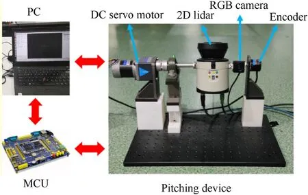
Fig.1.3D Laser scanning system.
As shown in Fig.1,the 3D laser scanning system consists of PC,MCU and pitching device.Based on the Robot Operating System(ROS),the PC collects and processes the image of the RGB camera,2D Lidar data,and encoder angle.The MCU is used to control the DC servo motor of the pitching device.The DC servo motor drives the 2D Lidar and RGB camera to swing,so that the target object or environment are scanned.Then the 2D Lidar data,the encoder angle and the image can be recorded,which are converted to construct the point cloud of the real environment.And the image is also used for target detection.3D laser scanning system adopts SICK 2D Lidar(LMS111-10100).The 2D Lidar parameters for 90% reflectance are shown in Table 1.Fig.2 shows the diagram of the 2D Lidar scanning range.

Table 1LMS111-10100 Lidar scanning parameters.
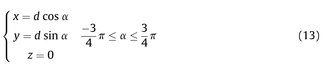
The 2D Lidar pitches around the center axis O and scan target objects in three-dimensional space.According to the geometrical relationship,the scanning range of the 3D laser scanning system is
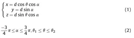
where x,y,z are coordinate values of the ground coordinate system,d is the detection distance of 2D Lidar,α is the scanning angle of 2D Lidar,θ is the pitching angle.
A 3D laser scanning strategy is designed for detecting objects with different motion states,as shown in Fig.3.The strategy is divided into MTRS and LMCS.Firstly,the color image information from the camera and the point cloud from the 2D Lidar are collected,and the motion state of the target object is estimated through the MTRS.Then the system changes the corresponding pitching motion parameters according to the LMCS.Finally,the DC servo motor adaptively adjusts the angle range and the pitching speed of the Lidar.
3.MTRS
In the case of using color cameras and 2D Lidar,the MTRS is designed to meet real-time requirements,as shown in Fig.4.MTRS is a cascaded deep neural network,which is divided into Yolov3-tiny and speed distance softmax network(SDSN).The color image and 2D point cloud of unknown environment are used as inputs.The classifications of target distance and speed are outputs,and the total number of classifications are nand n,respectively.
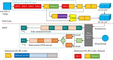
Fig.4.MTRS structure.

Fig.2.LMS100 Lidar scanning range.
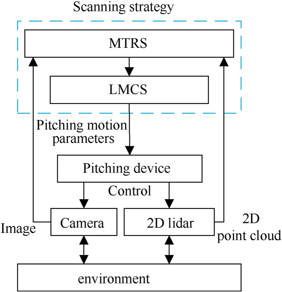
Fig.3.3D laser scanning strategy.
3.1.Yolov3-tiny
Yolo 3-tiny is a simplified version of Yolo3,whose backbone network uses a 7-layer-conv+max network to extract features.Yolo3-tiny requires a small amount of calculation,but the accuracy of remote target detection is not high.Focal loss adds coefficients to adjust the weight of the loss function for remote target,so the Yolo3-tiny is modified by focal loss function without affecting the real-time performance.For the binary cross entropy of loss function,the loss is modified to
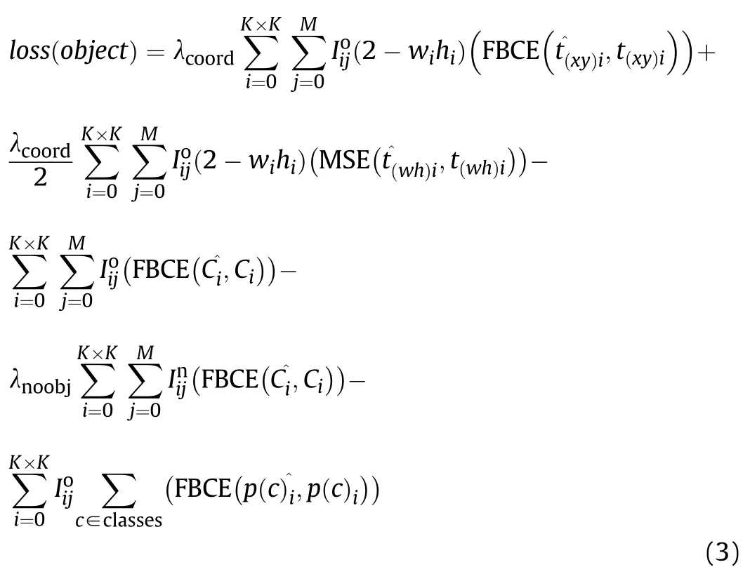
where λis loss coefficient from bounding box coordinate predictions,Idenotes whether the object appears in cell i and that the j anchor box is“responsible”for that prediction,tis the real coordinate vector of the bonding box center in cell i,tis the prediction coordinate vector of the bounding box center in cell i,tis the true length and width vector for bonding box in cell i,tis the prediction length and width vector for bonding box in cell i,w,hare the prediction length and width of bonding box in cell i,Cis the true confidence of the i cell,Cis the prediction confidence of the i cell,Idenotes whether object do not appear in cell i and that the j anchor box is not“responsible”for that prediction,λis the loss coefficient,p(c)is the real probability that the i cell contains the c target,and p(c)is the probability that the i cell contains the c target,MSE is quadratic loss function and the FBCE is

where pis the real label,pis the prediction probability,Cis the prediction confidence of the i cell,τ is the focal loss coefficient,and BCE is binary cross entropy loss function.
3.2.SDSN
3.2.1.SDSN structure
Fig.4 shows the SDSN structure,which is used to generate the classification of the target distance and speed.The network first extracts the 2D point cloud of the target based on the Yolov3-tiny target bounding box and the 2D Lidar point cloud.Thus,the scanning angle,distance of the target 2D point cloud and pitching angle can be achieved at this moment.Then the three features are fed into the fully connected network and the bidirectional LSTM network respectively to determine the classifications of the target distanceand speed.The fully connected network consists of fully connected layers and dropout layers.The bidirectional recurrent network consists of LSTM layers,Dropout layers and full connected layers.Their output is also softmax single-label multiclassification.For multiple objects,the minimum distance and maximum speed classifications are selected as control inputs.
Specifically,the Box selected layer is used to integrate the bounding box with the 2D point cloud.The coordinate of 2D point cloud on the image is obtained by the calibration matrix of Lidar and camera.Point m is(u,v)in the image coordinate system,and(x,y,0)in the Lidar coordinate system.The transformation relationship between Lidar and camera coordinate system is
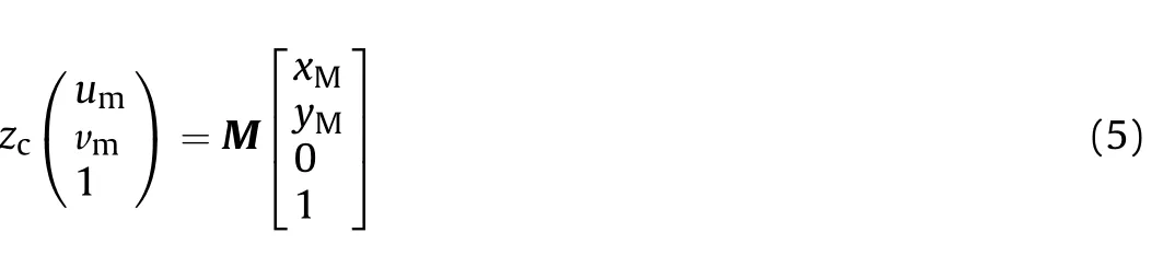
where zis the scale factor,and M is the union matrix of internal and external parameter.The target point cloud extraction equation is:
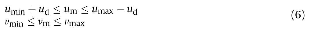
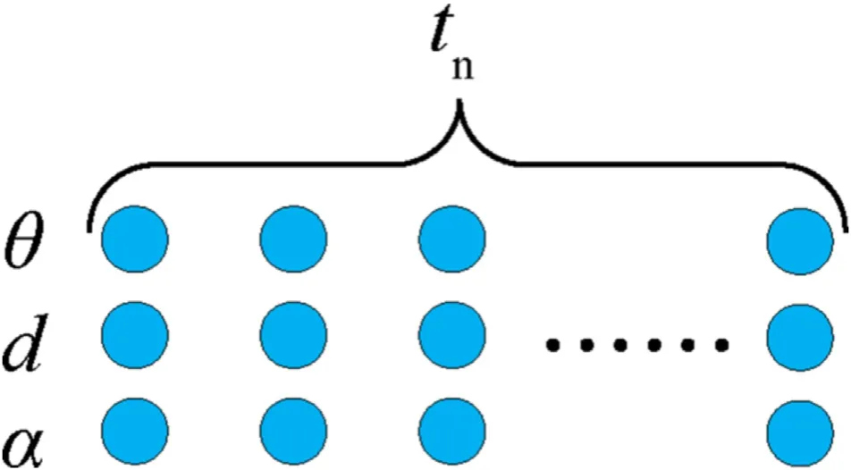
Fig.5.Input features of bidirectional LSTM network.
where u,u,v,vare the coordinates of the bounding box vertices,and uis the pixel deflation factor.The uis utilized to eliminate the point cloud,whose boundary does not belong to the target.In addition,the ACL layer is used to accumulate the sequence data required for bidirectional LSTM network.As shown in Fig.5,the feature sequence of ttime step is the input and the speed classification of the target is output.
3.2.2.SDSN loss
SDSN is a typical softmax multiclassification network,which generally uses cross entropy(CE)as the loss.However,the loss usually leads to overconfidence in the classification.The source of overconfidence is loss can be reduced by blindly increasing the vector module.In order to solve the problem,instead of the One Hot distribution,the training shall fit the uniform distribution.And for the problem of camera and Lidar calibration matrix error,focal loss is used to reduce the loss of indistinguishable samples again.The improved multiclassification loss function(FCE)is
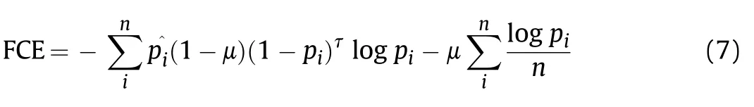
where pis the true label of class i,pis the predicted probability of class i,n is the total number of class,μ is the uniform distribution coefficient,and τ is the focal loss coefficient.
4.Design of LMCS
Based on the target motion parameters obtained in Section 3,it is necessary to design a corresponding LMCS to improve point cloud.Fig.6 is the diagram of the LMCS.Firstly,the Lidar pitching range and speed are determined based on the bionic Lidar pitching range model and the minimum matching speed model.Furthermore,the pitching motion of the Lidar is controlled accurately by the integral separate PID.

Fig.6.Lmcs.
4.1.Bionic Lidar pitching range model
Typical field of human eye is 124,which is shown in Fig.7.When looking at different objects,we adjust the view of our eyes to see them clearly according to the size and orientation of the objects.Similarly,the system imitates the characteristic of the human eye to take different scanning ranges according to different objects.Therefore,the bionic model can effectively reduce amount of useless information.As shown in Fig.7,The Lidar scanning range should cover the entire object.Therefore,based on the horizontal line,the bionic Lidar pitching range is
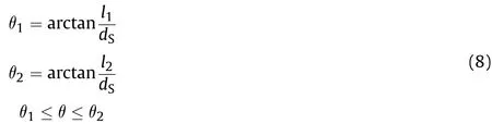
where lis the vertical height from the lowest point to the Lidar,lis the vertical height from the highest point to the Lidar,dis the distance of the object from the system,θis the angle between the line from the lowest point of the target object to the center of the Lidar and the horizontal line,θis the angle between the line from the highest point of the target object to the center of the Lidar and the horizontal line,and θ is the Lidar pitching angle.
4.2.Minimum matching speed model
4.2.1.Coordinate system
To calculate the minimum matching rotational speed for 2D Lidar pitching,the motion of the Lidar and target in 3D space shall be well defined.Three coordinate systems,namely ground coordinate system O,Lidar coordinate system A and target coordinate system B,are established and shown in Fig.8.
The initial position and orientation of the Lidar coordinate system A is the same as the ground coordinate system O.The Lidar rotates around the yaxis.The rotation matrix of ground coordinate system O relative to Lidar coordinate system A is
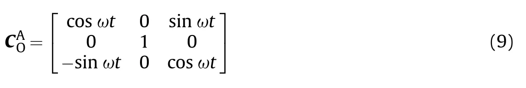
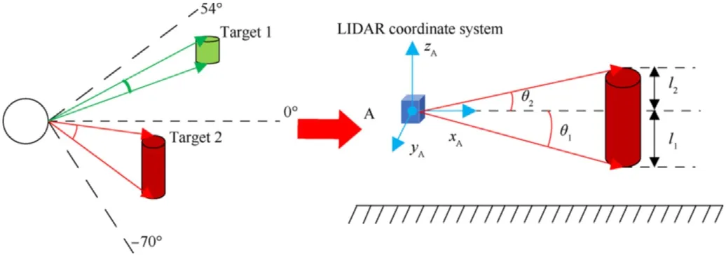
Fig.7.Bionic Lidar pitching range model.

Fig.8.Coordinate system description.
where ω is the Lidar pitching angle speed,and t is time.The initial position and orientation of target coordinate system B is arbitrary.And the target is moving in a straight line along the xaxis.The speed is
where vis the speed component of the target object in the xdirection.Similarly,the rotation matrix of the target coordinate system B relative to the ground coordinate system O is
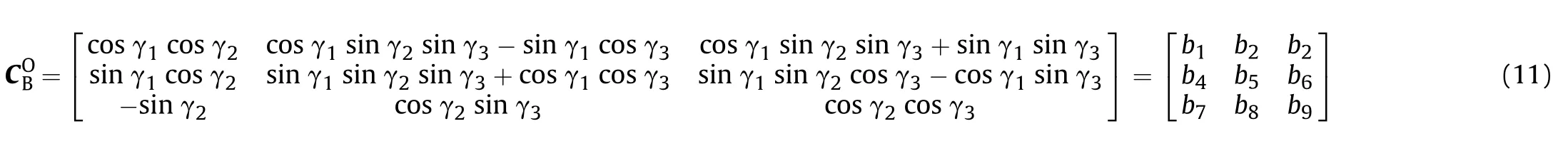
where γis the angle of rotation around the zaxis,γis the angle of rotation around the xaxis,and γis the angle of rotation around the yaxis.
4.2.2.Minimum matching speed calculation
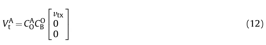
In the Lidar coordinate system,the Lidar and its scanning plane can be regarded as stationary.In the target coordinate system,the target is moving at a constant speed along the xaxis.The speed ofthe target in the target coordinate system can be converted to the speed in the Lidar coordinate system according to Eq.(12).As shown in Fig.9,from the perspective of Lidar coordinate system,the scanning plane is a three-quarters circle,and the target has a certain motion trajectory in Lidar coordinate system.The problem can be transformed into the intersection point between the motion trajectory and the scanning plane during the period of pitching motion.The motion speed of the target object can be converted to the Lidar coordinate system,the motion is:
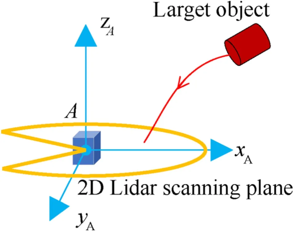
Fig.9.Schematic of Lidar capture target.
Based on the scanning range of the 2D Lidar,the parametric equation of the scanning plane is
where d is the detection distance of 2D Lidar,and α is the scanning angle of 2D Lidar.According to Eqs.(12)and(13),the coordinates of the target in the Lidar coordinate system is
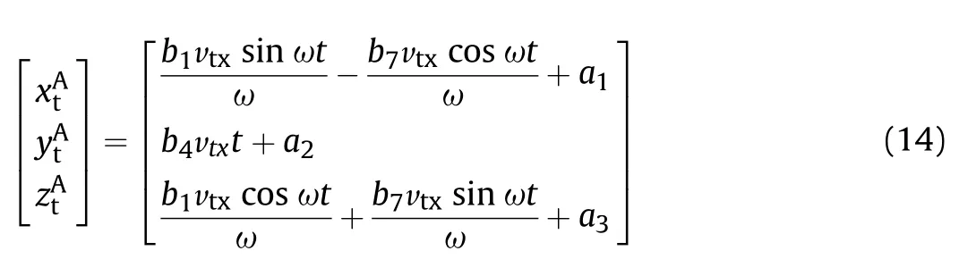
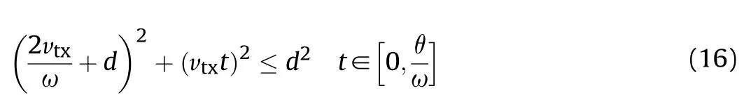
where a,aand aare integral coefficients.According to Eqs.(13)and(14),the inequality for existence of intersections is:

where t is the time the target object remains in the scanning range.The initial position of the target is set to(d,0,0).Eq.(17)is simplified by Scaling algorithm to
The appropriate matching speed formula is
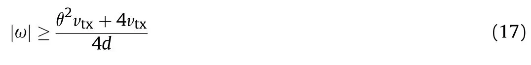
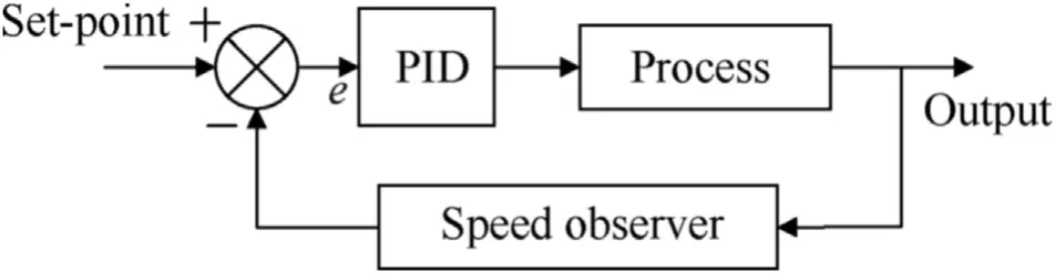
Fig.10.Integral separate speed PID.
4.3.Integral separate speed PID
An integral separate PID control algorithm modified by a speed observer is proposed,as shown in Fig.10.First,the speed observer is used to extract the pitching speed.Then,the integral separate PID is applied to realize the accurate control of Lidar pitching motion.The speed observer is
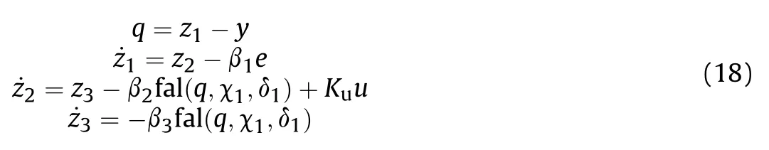
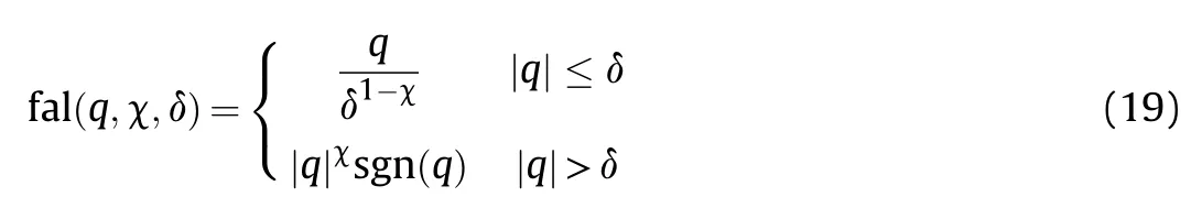
where y is the input signal,z,z,zare the observer state variables,β>0(i=1,2,3),χand δare the observer coefficients,and u is the input signal of the observed system.fal(q,χ,δ)is saturation function whose function is to suppress signal jitter:
The input signal is pitching angle.According to Eqs.(18)and(19),the expansion amount zis derived,which realizes the estimation of the pitching speed.Based on the speed observer,the integral-separation PID is adopted.When the error is large,the integral item is cancelled to avoid large overshoot.Otherwise,the integral item is introduced to eliminate the static error and improve the accuracy.The improved PID control law is
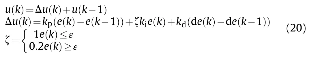
where e(k)is the error of zfrom the set value,de(k)is the error of zfrom the derivative of the set value,u(k)is the controller output,k,k,kare the proportionality coefficient,integral coefficient and derivative coefficient,ζ is the switching coefficient of the integration term,and ε is the error threshold.
5.Experiments
This section provides experimental analysis and validation of MTRS,LMCS and 3D laser scanning strategy.Firstly,the accuracy of MTRS is verified with the human target.Then the PID algorithm is used to control the Lidar pitching motion,and the corresponding system response curve is obtained to evaluate the control performance.Finally,the two strategies are combined to verify whether the 3D laser scanning strategy can effectively improve point cloud.Fig.11 is the point cloud reconstructed from the 3D laser scanning system,with the scanning time of 18 s.
5.1.MTRS experiment
5.1.1.Yolov3-tiny experiment
Based on the MTRS proposed in Section 3,Yolov3-tiny is used toidentify the moving object in the scene.Firstly,we construct a dataset targeting people,and collect various types of samples in the laboratory,outdoor,dark,daytime and multiple objects.The network training parameters are shown in Table 2.

Table 2Yolov3-tiny training parameters.
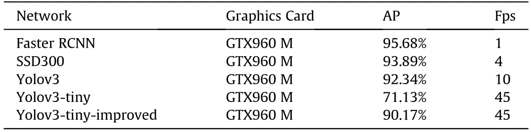
Table 3Network comparison.

Fig.11.3D reconstruction of point cloud.
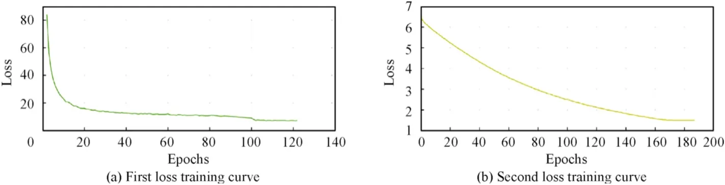
Fig.12.Yolov3-tiny loss training curve.
The network training is divided into two stages.In the first stage,the last two layers of the network are frozen and the original loss function is used for training.Then the last two layers of the network are thawed for training.The second stage uses the improved loss function for the second training to derive the final weights.The first and second stages loss training curves are shown in Fig.12.
Table 3 shows the accuracy and frame rate comparison of Faster RCNN,SSD300,Yolov3,Yolov3-tiny first training(Yolov3-tiny)and second training(Yolov3-tiny-improved).The Yolov3-tiny-improved can satisfy the real-time and accuracy requirements of strategy execution.
Fig.13 shows the results of Yolov3-tiny identification at different locations in the laboratory scenario.In each image,Yolov3-tiny generates the bounding box of target object accurately.The average identification time of each frame is 0.022 s.
5.1.2.Calibration matrix of lidar and camera experiment
Based on the target motion parameter model in Section 3.2,the 2D Lidar and camera are first calibrated.A calibration method based on point and line features is used to derive the internal and external parameter union matrix of the camera relative to the Lidar:
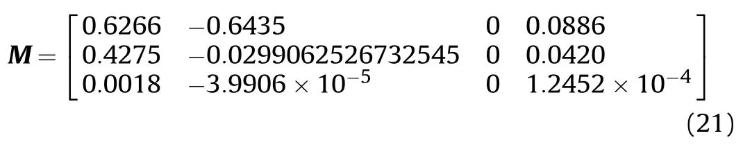
The 2D point cloud is mapped to the color image as shown in Fig.14.
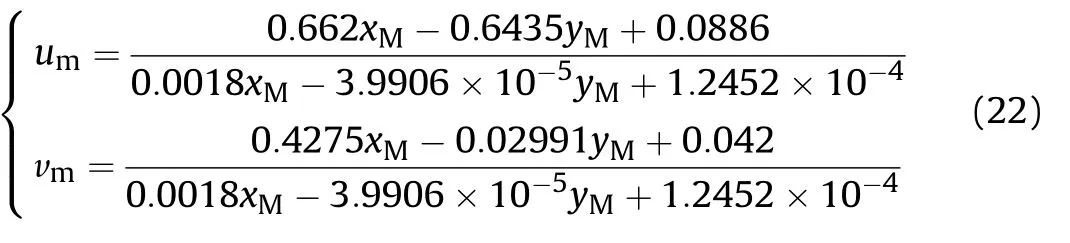
Therefore,according to Eq.(5),the conversion formula is
5.1.3.SDSN experiment
Based on the experimental results of Sections 5.1.1 and 5.1.2,the SDSN network data set is constructed and trained.The network training parameters are shown in Table 4.
To investigate the effect of improved loss on network training,the fully connected network is compared using cross-entropy and improved cross-entropy respectively.The training loss curve is obtained as shown in Fig.15(a).
As the number of iterations increases,the decreasing trend of the improved loss is greater.Fig.15(b)shows the accuracy comparison curve of the test set.The FCE can effectively improve the accuracy of the model,improving the accuracy from 80.7% to 96.87%.And the average prediction time is 0.026 ms.
Similarly,the influence of loss function on bidirectional LSTMnetwork is compared.The training loss curve is obtained as shown in Fig.16(a).It can be seen that as the number of iterations increases,the loss of both CE and FCE decreases.However,as shown in Fig.16(b),the test set accuracy is not improved.And comparing FCE,the test set accuracy increases to 96.97%.And the average prediction time is 0.134 ms.
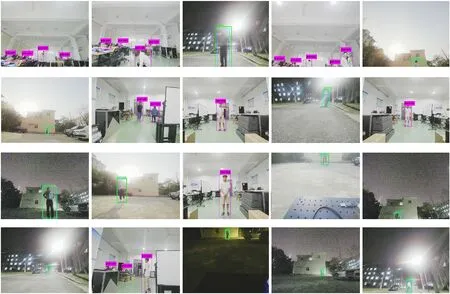
Fig.13.Yolov3-tiny results.
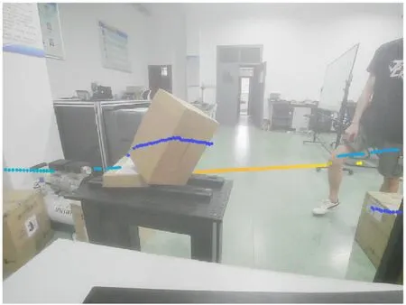
Fig.14.Calibration result of the camera relative to the Lidar.
5.2.LMCS experiment
5.2.1.Integral separate speed PID experiment
The PID algorithm with speed as control objects is adopted and the initial parameters are set as shown in Table 5.The sampling time is 0.05 s.The comparison curves of PID pitching speed and the ideal curve are shown in Fig.17.It can be seen that the PID pitching speed curve basically matches the ideal curve,with an average speed error of 0.6439/s.But there is apparent overshoot in each turn.
In order to avoid the overshoot,the integral separation PID control algorithm is adopted.The modified parameters are shown in Table 6.

Table 4SDSN training parameters.

Table 5PID parameters 1.
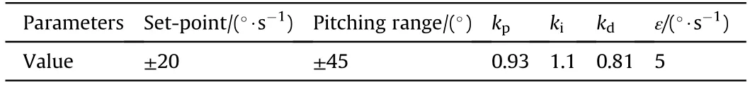
Table 6PID parameters 2.
The pitching speed of integral separated PID can be compared with the ideal curve as shown in Fig.18.The overshoot during turning has almost been removed and the average error is reduced to 0.4239/s.
For exploring the PID control performance on occasions of frequent acceleration,deceleration and range variation,different pitching speeds and ranges are set to change simultaneously,as shown in Fig.19.The PID control algorithm can still respond quickly to reach the target speed and range.The maximum response time is 0.13 s.In conclusion,the PID control algorithm can control thepitching motion of the 2D Lidar accurately.
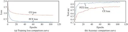
Fig.15.Training curve of fully connected network.
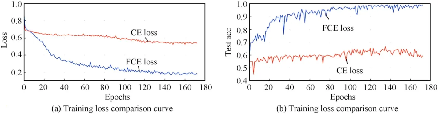
Fig.16.Training curve of bidirectional recurrent network.
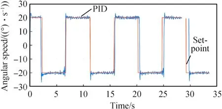
Fig.17.Speed PID square wave response curve.
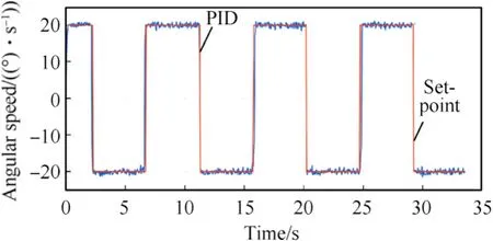
Fig.18.Integral separation of PID square wave response curve.
5.2.2.Bionic Lidar pitching range model experiment
This section verifies the influence of pitching range on the scanning results.Fig.20(a)shows the mismatch scanning results.It can be seen that the Lidar spends a large portion of its entire pitching motion cycle scanning for useless information.These point cloud does not contain the target.The target point cloud of a certain period of time will be lost,and the set range is too small to detect the complete target.Fig.20(b)shows the pitching range adjusted by the range model in Section 4.1.After the target being detected,the system adaptively adjusts the pitching angle,so that the target can be detected throughout the Lidar pitching cycle,which means that useful information is being collected continuously.
5.2.3.Minimum matching speed experiment
To verify whether the minimum matching speed can effectively improve the 3D laser scanning system,the target leaves the detection range of the 3D laser scanning system at different speeds.Then different Lidar pitching speeds are taken and the point cloud generated are compared to draw a conclusion.The target speeds and pitching speeds are shown in Table 7.

Table 7Pitching speed parameters.
By comparing Fig.21(a)and(c),the Lidar pitching speed has a great influence on the target point cloud.For a target with speed of 3 m/s,the pitching speed of 5/s is too slow,resulting in excessive deformation of the target point cloud.However,the fast pitching speed of 24/s produces a relatively sparse point cloud.Fig.21(b)shows dense and clear target point cloud be generated by the minimum matching speed.Therefore,for the 3D laser scanning system,the corresponding minimum matching speed should be adopted to improve the quality of the point cloud.
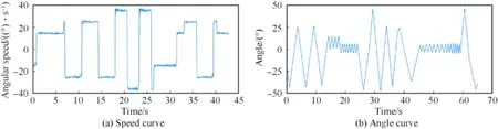
Fig.19.Pitching motion curve.

Fig.20.Influence of range on scanning results.
5.3.Scanning strategy experiment
Based on the overall 3D laser scanning strategy,the scanning capture experiment of target movement in real environment is carried out.By combining the MTRS prediction time and pitching motion response time,the average strategy execution time is 0.1521 s.The evaluation indexes of point cloud scanning results are shown in Table 8.
Simulation experiments are performed under outdoor.According to Eqs.(8)and(17),the Lidar pitching motion parameters are set,as shown in the Table 9.
Set the different speed of 1 m/s,3 m/s and 5 m/s,and select the corresponding pitch motion parameters to compare the evaluation index,as shown in Tables 10—12.As the target speed increases,the number of complete target point cloud frames and density decreases.As the pitching speed increases,the TAP also increases,but the point cloud density decreases.And combined with the random motion for a fixed time in Table 13,the evaluation indexes of the adaptive scanning strategy are optimal.Therefore,it can be concluded that the scanning strategy can eliminate velocity mismatch distortion,improve point cloud integrity and increase point cloud density while ensuring the TAP.
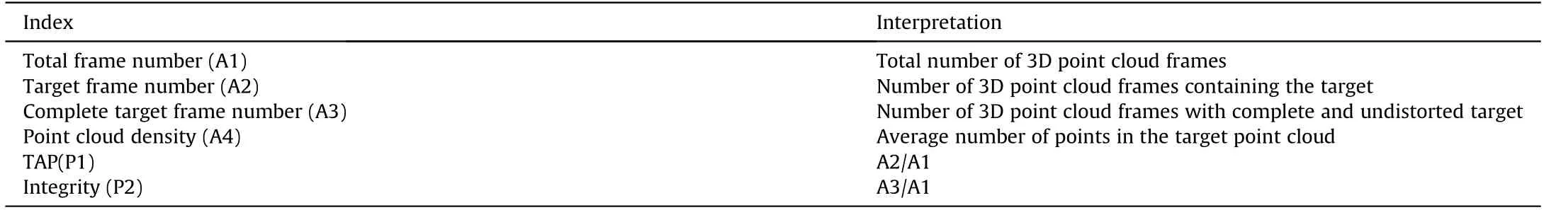
Table 8Evaluation indexes.
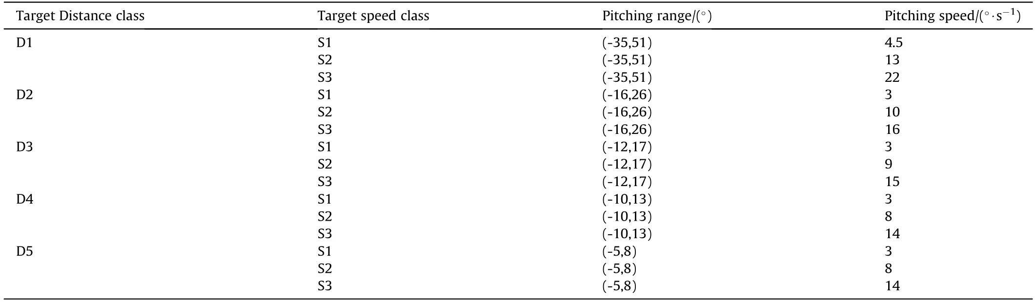
Table 9Pitching motion parameters.
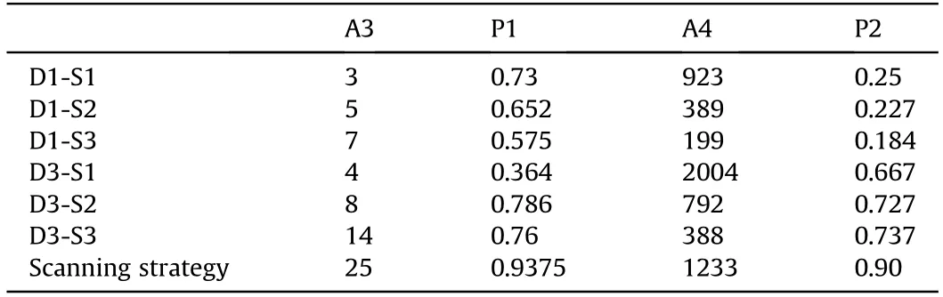
Table 10Evaluation indexes of 1 m/s.
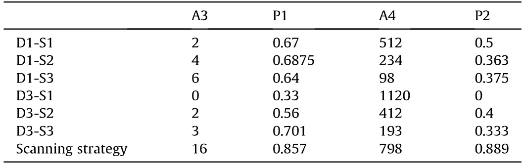
Table 11Evaluation indexes of 3 m/s.
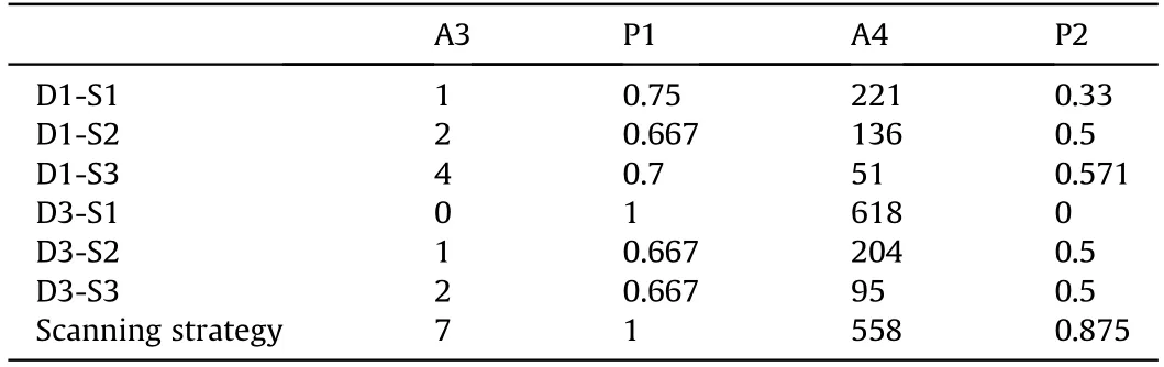
Table 12Evaluation indexes of 5 m/s.
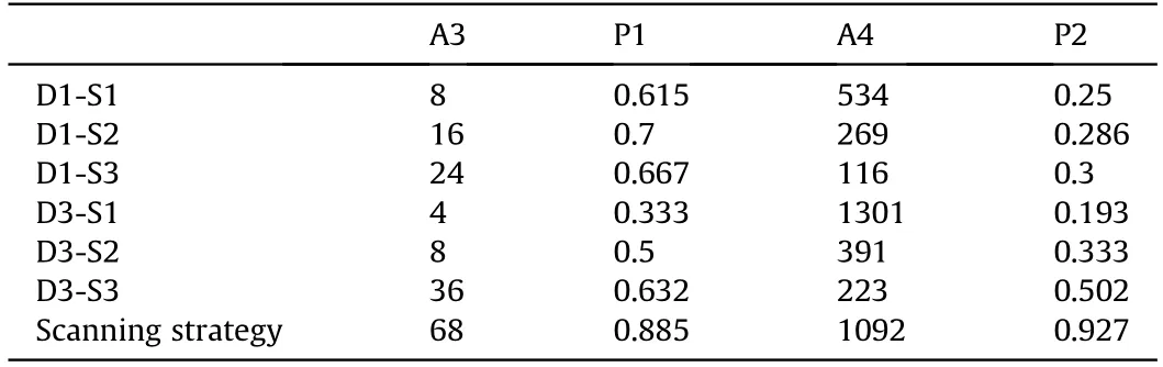
Table 13Evaluation indexes of random motion.
6.Conclusions
In this paper,a 3D laser scanning strategy is designed for 2DLidar pitching device,and the strategy is divided into MTRS and LMCS.It combines the characteristics of the device and uses cascaded deep neural networks to identify the target motion state.Then,based on the bionic range model and the minimum matching speed model,the system adaptive scanning is realized by the speed PID control algorithm.
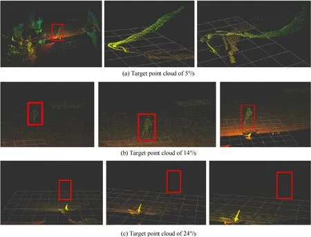
Fig.21.Influence of speed on scanning results.
(1)For MTRS,the proposed cascade neural network is experimented.Experiments show that Yolov3-tiny can improve the target recognition accuracy from 71.13% to 90.17% by using the improved loss function while ensuring the frame rate.SDSN uses the improved cross entropy loss function to improve the distance class detection accuracy from 80.7%to 96.87% and the speed class detection accuracy to 96.97%.
(2)For LMCS,the improved PID control algorithm can meet the control requirements of frequent acceleration and deceleration with variable range in real time,and the average speed error is 0.4239/s.The bionic range model can effectively reduce the collection of useless information,and the minimum matching speed model can effectively reduce the deformation phenomenon of the target point cloud.
(3)Finally,the overall scanning strategy is experimented to simulate different motion states in real scenes and the average strategy execution time is 0.1521 s.The results show that the scanning strategy can eliminate speed mismatch distortion,improve point cloud integrity and increase point cloud density while ensuring the TAP.
The authors declare that they have no known competing financial interests or personal relationships that could have appeared to influence the work reported in this paper.
This research was funded by National Natural Science Foundation of China(Grant No.51805146),the Fundamental Research Funds for the Central Universities(Grant No.B200202221),Jiangsu Key R&D Program(Grant Nos.BE2018004-1,BE2018004)and College Students'Innovative Entrepreneurial Training Plan Program(Grant No.2020102941513).

- Defence Technology的其它文章
- Damage analysis of POZD coated square reinforced concrete slab under contact blast
- Autonomous maneuver decision-making for a UCAV in short-range aerial combat based on an MS-DDQN algorithm
- The properties of Sn—Zn—Al—La fusible alloy for mitigation devices of solid propellant rocket motors
- The surface activation of boron to improve ignition and combustion characteristic
- Numerical investigation on free air blast loads generated from centerinitiated cylindrical charges with varied aspect ratio in arbitrary orientation
- Natural convection effects on TNT solidification inside a shaped charge mold