
Experimental study on propagation characteristics of rotating detonation wave with kerosene fuel-rich gas
2022-08-30 14:33:32JiaxiangHanQiaodongBaiShijianZhangFangWangChunshengWeng
Defence Technology 2022年8期
Jia-xiang Han,Qiao-dong Bai,Shi-jian Zhang,Fang Wang,Chun-sheng Weng
National Key Laboratory of Transient Physics,Nanjing University of Science and Technology,Nanjing,210094,China
Keywords:Rotating detonation wave Kerosene fuel-rich gas Initiation process Propagation mode
ABSTRACT In this study,kerosene fuel-rich gas produced by the combustion in the gas generator was used as the fuel and oxygen-rich air was used as the oxidant to investigate the propagation characteristics of the rotating detonation wave(RDW).The initiation of the kerosene fuel-rich gas and propagation process of the RDW were analyzed.The influences of the oxygen content in the oxidizer,kerosene mass flow rate of the gas generator,and temperature of the kerosene fuel-rich gas on the propagation process of the RDW were studied.The experimental results revealed that the propagation velocity of the RDW could be improved by increasing the three parameters mentioned above with the kerosene mass flow rate as the strongest factor.The minimum oxygen content that could successfully initiate and maintain the stable propagation of the RDW was 32%,achieving the RDW velocity of 1141.9 m/s.The RDW mainly propagated as two-counter rotating waves and a single wave when the equivalent ratios were 0.62-0.79 and 0.85-0.87,respectively.The highest RDW velocity of 1637.2 m/s was obtained when the kerosene mass flow rate,oxygen content,and equivalent ratio were 74.6 g/s,44%,and 0.87,respectively.
1.Introduction
Continuous rotating detonation engine(CRDE) is a new type of engine that utilizes a rotating detonation wave(RDW) to generate thrust in a rotating detonation combustor (RDC).After an RDW passes through combustible mixtures,the high-temperature and high-pressure products generated expand,and are discharged from the end of the RDC at a high speed,thereby generating thrust.CRDEs have broad application prospects and offer advantages,such as high thermal cycle efficiency,fast heat release rate,compact structure,and wide working range.Therefore,CRDEs have attracted extensive attention in the field of hypersonic propulsion technology.
The formation and propagation characteristics of the RDW with hydrogen as the fuel have been widely studied[1-3].The effects of the oxygen volume fraction,mass flow rate,and equivalent ratio on the propagation of continuous RDW have been studied in a circular RDC [4].Moreover,experimental studies on the combustion characteristics and working principle under poor fuel conditions have been conducted [5].The effects of the combustion chamber configurations on the RDW propagation mode [6],relationship between high-frequency tangential instability and continuous rotating detonation[7],and flow field structure in a stable working mode [8] have been investigated.In addition,there have been numerical studies on the H/air RDW flow field and propagation characteristics of the shock wave at the head of the combustor[9],and mechanism of chemical dynamics of a CRDE [10].
Kerosene,which is the optimum fuel used in hypersonic propulsion system,has the advantages of high calorific value,satisfactory combustion performance,convenience of use and maintenance,non-toxicity,and strong controllability,among others.However,the ignition of liquid kerosene remains a challenge because of the difficulty of atomization and uneven mixing process.Rotating detonation using kerosene as the fuel has been experimentally investigated by adding hydrogen,oxygen,or heated air to the reactants to improve the activity of combustible mixtures,thereby minimizing the challenges associated with liquid hydrocarbon fuel initiation.Stable rotating detonation was successfully achieved using liquid kerosene as the fuel with hydrogen [11],syngas additives[12],and excess oxygen[13,14].Further,preheated liquid hydrocarbon fuel with heated air[15,16]was also applied to facilitate rotating detonation.The effects of the total pressure,equivalence ratio,and total inlet temperature on the working performance of kerosene/air rotating detonation have also been studied [17-19].Furthermore,the reactivity of liquid hydrocarbon fuel has been studied,and improved through vaporization,cracking,or precombustion to mitigate the challenges associated with its initiation.
A mixture of ethylene-acetylene-hydrogen gas has been used as a substitute of precombustion-cracked kerosene to investigate the rotating detonation characteristics [20-22].The detonation delay time and propagation characteristics of an RDW have also been studied using methane-hydrogen-carbon dioxide as the fuel and air as the oxidant[23].Furthermore,the effects of the fuel ratio[24],refueling method,and refueling distance [25] on the distribution of pyrolysis products have been studied to realize kerosene/air rotating detonation without adding hydrogen and oxygen.The influence of the channel and oxidizer injection slot width on the rotating detonation characteristics of the precombustion-cracked kerosene has also been investigated [26-28].An experimental study has been carried out on the process of rotating detonation combustion using the scheme of the secondary detonation combustion of kerosene fuel-rich gas (KFRG) and oxygen-rich air after the primary combustion of liquid kerosene [29].Additionally,the influence of the nozzle configuration on the rotating detonation characteristics of pyrolysis gas in kerosene precombustion was studied [30],and a two-dimensional numerical simulation was conducted to study the initiation process of kerosene,which was partially cracked by preheating and subsequent ignition [31].
Owing to the complex composition of KFRG,its rotating detonation propagation characteristics are different from those of existing conventional fuels;thus,a fundamental understanding of the rotating detonation propagation characteristics of KFRG is required.To date,only a few studies have investigated the influence of the width of the inlet ring,width of the combustion chamber,equivalent ratio,and oxygen content of the oxidizer on the rotating detonation using KFRG as the fuel.Further,research on the characteristics of RDW of KFRG is currently in its initial stage.
In this study,a precombustion method of kerosene was adopted to form KFRG,thereby reducing the difficulty of initiating liquid kerosene.The initiation of KFRG and propagation characteristics of the RDW were experimentally studied.The influences of the oxygen mass fraction,kerosene mass flow rate,and gas temperature on the propagation of the RDW of KFRG were further explored.The results were compared with those of the rotating detonation of liquid kerosene.This paper reports the results of the investigation of multi-component mixtures in the rotating detonation phenomenon.The experimental results can be used in the research of combined air turbine rocket detonation engine for future studies.
2.Experimental apparatus and measurement system
The experimental system and experimental equipment photo for the rotating detonation of KFRG are shown in Fig.1.It includes a fuel/oxidant supply system,control system,data acquisition system,hot jet ignition system,KFRG generator,and RDC.The data acquisition system comprised a static pressure sensor,highfrequency dynamic pressure sensor (PCB),turbine flowmeter,and temperature sensor.
The KFRG generator comprised an injection section,combustion chamber,and nozzle.Kerosene and precombustion oxygen were injected into the combustion chamber,burned to form the KFRG,and subsequently passed through the nozzle into the KFRG collection chamber.The KFRG pressure in the combustion chamber was controlled by changing the nozzle throat diameter.Jet fuel no.3 was used in the experiment.
The inner and outer diameters of the RDC were 94 mm and 110 mm,respectively.The width and length of the combustion chamber were 8 and 180 mm,respectively.The KFRG was injected into the rotating combustion chamber through 80 circular holes uniformly distributed on the inner wall with a total injection area of 40.19 mm.The combustible mixture was ignited by a hot jet.
High-frequency dynamic pressure sensors were installed on the wall surface of the hot jet tube (PCB0) and RDC (PCB1,PCB2,and PCB3).The pressure sensors installed on the circumferential plane were aligned with the ignition position and evenly distributed at an angle of 120,as shown in Fig.2.The sampling frequency was set to 500 kHz.
Static pressure sensors were installed on the oxygen gas collecting chamber,combustion chamber,KFRG collecting chamber,air collecting chamber,and outer wall surface of the RDC,labelled as P1,P2,P3,P4,and P5,respectively.Temperature sensors were installed on the gas generator combustion chamber,and KFRG collecting chamber,labelled as T1 and T2,respectively,as shown in Fig.1.
Fig.1.(a) Schematic of the rotating detonation experimental system for KFRG;(b).Photo of experimental equipment.
Fig.2.Installation position of the high-frequency dynamic pressure sensors.
The time sequence of the experiments is shown in Fig.3.The data acquisition system was operational throughout the experimental process.After the stabilization of the process in the gas generator,the hydrogen/oxygen mixture in the hot jet tube was ignited to produce high-temperature and high-pressure jet flow into the RDC.The KFRG/oxygen-rich air mixture was subsequently ignited to form an RDW.
Fig.3.Time sequence of the experiments.
In this study,the mass fraction of oxygen in the oxidizer,kerosene mass flow rate,and gas temperature were used as the variables.The control variable method was used to design the experimental conditions.A total of 14 groups of experimental conditions were set to analyze the propagation characteristics of the RDW of the KFRG under various conditions.The ambient temperature and environmental pressure were 288 K and 1 atm,respectively.
3.Results and discussion
Table 1,Table 2,and Table 3 present the influence of the oxygen mass fraction in the oxidizer on the RDW velocity,kerosene mass flow rate on the RDW wave velocity and mode,and KFRG temperature on the RDW formation and propagation velocity,respectively.The detailed discussion of the results is presented in the subsequent sections.
Table 1.Experimental parameters and results with varying oxygen mass fraction.
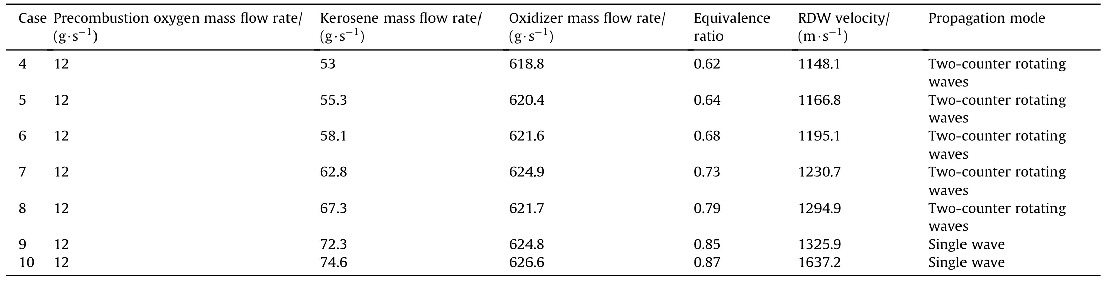
Table 2.Experimental parameters and results with varying kerosene mass flow rate at 44% oxygen mass fraction.
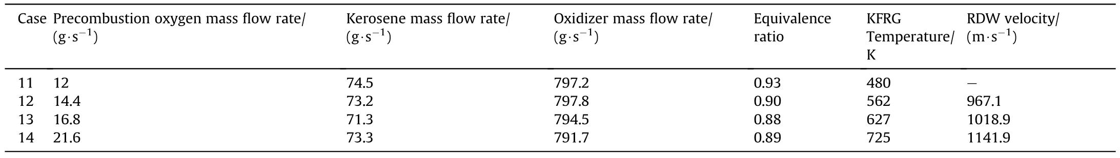
Table 3.Experimental parameters and results with varying gas temperature at 32% oxygen mass fraction.
3.1.Initiation of the RDW of KFRG
The RDW initiation of the KFRG was analyzed for case 2.Fig.4 shows the static pressure history of the gas generator and RDC.Fig.4(a) shows the pressure history of the gas generator oxygen chamber(P1)and combustor(P2).When oxygen was injected into the gas generator at 1.1 s,P1 gradually increased and reached an equilibrium point of 0.74 MPa at 1.8 s.At 2.6 s,the high-energy spark plug ignited,resulting in an ignition pressure peak owing to the fuel residue.At 3.2 s,P2 increased owing to the large amount of KFRG generated in the gas generator.At 4.0 s,P2 and P1 exhibited steady state pressures of 1.09 and 1.25 MPa,respectively.At 4.388 s,the hot jet tube was ignited,and the RDC operation began.The pressure of the rotating detonation in the RDC increased the P2 to 1.12 MPa.As the kerosene supply was terminated at 5.1 s,P2 slightly increased owing to the combustion of the residual kerosene,and subsequently sharply decreased.
Fig.4(b) shows the pressure history of the KFRG collecting chamber(P3),air collecting chamber(P4),and RDC(P5).The trend of P3 was similar to that of P2.Air was injected into the RDC at 2.6 s,and oxygen was added to the air chamber at 3.1 s.Subsequently,oxygen-rich air was formed,thereby P4 reached 0.39 MPa.At 4.388 s,hot jet was injected into the RDC.Owing to the back pressure of the rotating detonation,P4 and P5 reached 0.49 and 0.22 MPa,respectively.At 5.1 s,kerosene supply was shut down,thereby rapidly decreasing P4 and P5.
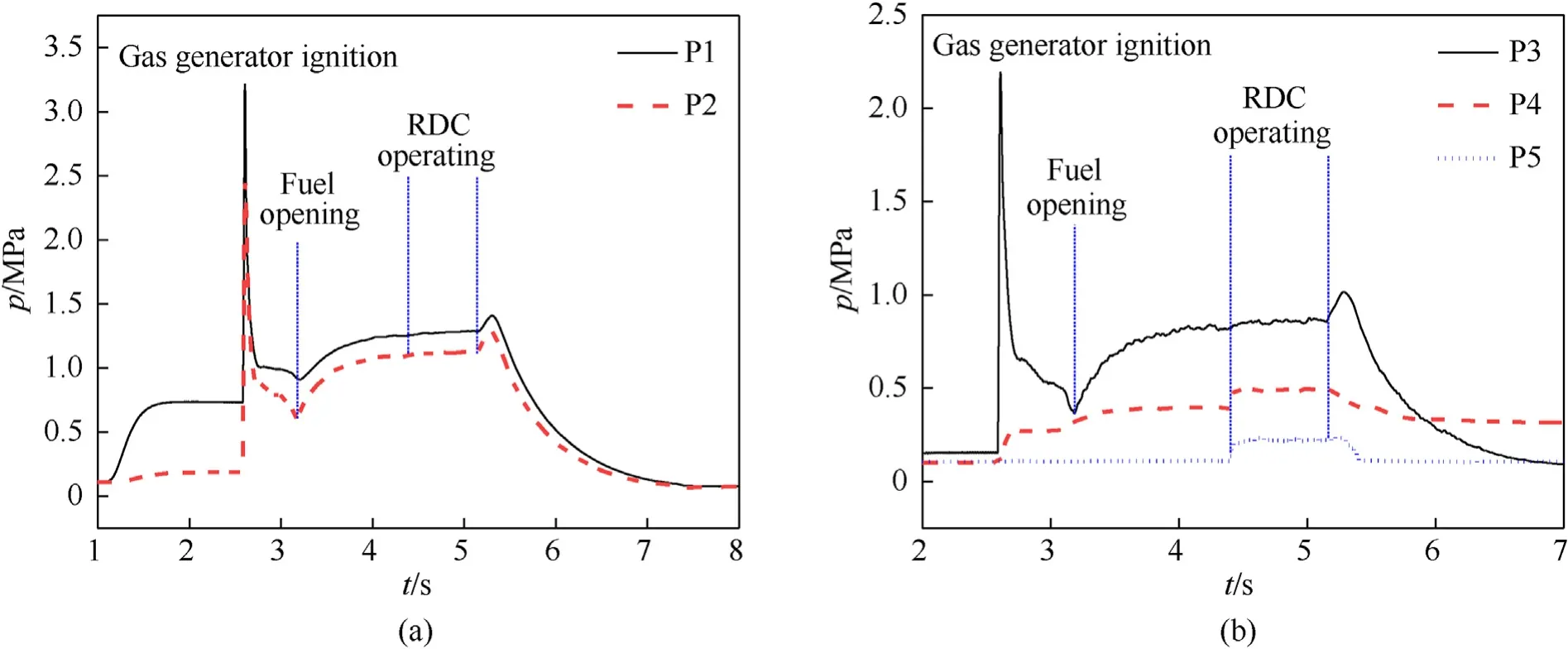
Fig.4.Static pressure history under case 2: (a) P1 and P2;and (b) P3-P5.
Fig.5 shows the high-frequency dynamic pressure history obtained at PCB0,PCB1,and PCB2 during the ignition process of the rotating detonation.In this study,the high-frequency dynamic pressure data acquisition was triggered 4 s after the signal acquisition,that is,the time corresponding to 0 s of the high-frequency dynamic pressure data corresponds to 4 s of the overall experimental signal acquisition data.The hot jet tube was ignited at 387.4 ms.After 0.9 ms,the hydrogen and oxygen mixture in the hot jet tube was ignited to produce a thermal jet.PCB0 captured the ignition pressure peak of 1.02 MPa.After Δt,PCB1 recorded a peak pressure of 0.99 MPa at 388.3 ms owing to the hot jet generated in the hot jet tube and injected into the RDC.After the injection of the hot jet into the RDC,the pressure peak oscillated irregularly.Here,deflagration combustion occurred in the combustor,and the RDW was not immediately formed.After t,under the combined action of the shock wave reflection,friction,and turbulence in the combustion chamber wall,and continuous injection of fresh KFRG/air combustible mixtures,the deflagration wave developed into a detonation wave.PCB1 captured a pressure peak of 0.72 MPa at 390.2 ms.Subsequently,an RDW was formed in the RDC and gradually stabilized,from which the deflagration to detonation transition(DDT)process was completed,indicating that tlasted approximately 2 ms.

Fig.5.High-frequency dynamic pressure of PCB0,PCB1,and PCB2 during the ignition process.
Fig.6 shows the RDW pressure at the ignition process in case 6,case 8,and case 9.The time for the formation of the RDW was identified as the delay time from the formation of the hot jet to the formation of a stable RDW,which was equal to 1.1 ms,1.6 ms,and 2.4 ms for case 6,case 8,and case 9,respectively.As the kerosene mass flow rate was increased,the tneeded for RDW formation from the DDT gradually increased because of the increased product volumes of the KFRG.As the mass ratio of the fuel injected into the RDC increased,the mass proportion of the oxidizer decreased,and the overall reactivity of the combustible premixed gas decreased.Thus,the DDT process required a longer time for completion.
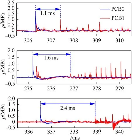
Fig.6.Rotating detonation delay time in case 6,case 8,and case 9.
3.2.RDW propagation process of KFRG
The analysis of the RDW propagation process of the KFRG revealed the significant effect of the equivalence ratio on its propagation mode.With the equivalence ratio of 0.62-0.79,a mixed propagation mode dominated by two-counter rotating waves and supplemented by a single wave was noted.With the equivalence ratio of 0.85-0.87,a single-wave RDW propagation mode was observed.The characteristics of the rotating detonation under different propagation modes are analyzed as follows.
3.2.1.Mixed RDW propagation mode
A mixed RDW propagation mode indicates that single-wave and two-counter RDW propagation modes alternately appear in one experimental cycle.Based on case 2,the propagation of the RDW of the KFRG was analyzed with an equivalence ratio of 0.76.In the single-wave propagation mode,the RDW rotated and propagated in one direction within the RDC,and the pressures at PCB1 and PCB2 alternately and regularly increased.In the two-counter RDW propagation mode,two RDWs propagated towards each other in the RDC,and the two waves collided twice per cycle.The PCB pressure near the collision point became similar to that in the single-wave mode,and the PCB at other positions captured two pressure peaks within one cycle.Fig.7 shows the high-frequency dynamic pressure with respect to time.The dynamic RDW pressure peak captured by PCB1 constantly fluctuated owing to two reasons: the uneven composition of KFRG in RDC,and changes in the RDW propagation between a single-wave and two-counter rotating wave modes.Under a single-wave propagation mode,the pressure peak was relatively stable and fluctuated at approximately 1.2 MPa.Under the two-counter rotating wave propagation mode,and the collision point at PCB1,a high-pressure peak was generated.However,for a collision points different from PCB1,the pressure peak was low.
Fig.8 illustrates the pressure at PCB1 and PCB2 in the singlewave propagation mode.At 486.6-493.95 ms,the RDW propagated for 25 cycles in the RDC with the pressure peak in the order of a→b→c→d,which is a typical codirectional rotating mode.As viewed from the RDC exit end,i.e.,counterclockwise,the rotating direction was from PCB1 to PCB2.According to the time and distance of the RDW propagating for 25 cycles,its average propagation velocity was 1191 m/s,as calculated using Eq.(1) and Eq.(2).


where L is the total propagation distance of the RDW,K is the number of detonation wave propagation periods,and D is the outer diameter of the RDC,D=0.11 m.
The transient propagation and average frequency of the RDW was calculated using Eq.(3) and Eq.(4),respectively.
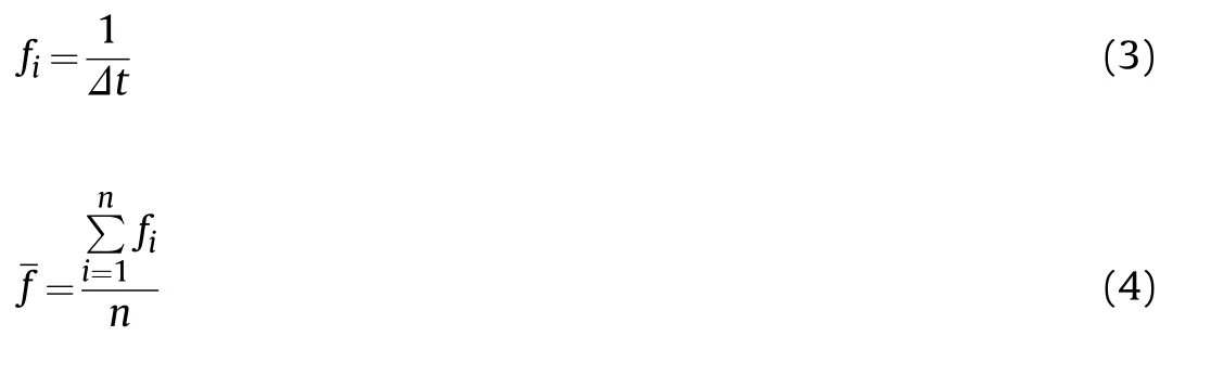
where f is the dominant frequency and n is the number of cycles.In Fig.8,the transient frequency of a Δt cycle was 3846 Hz,and the average dominant frequency of the RDW propagation for 25 cycles was 3486 Hz.
Based on the analysis of the RDW pressure peak sequence,calculated wave velocity,and dominant frequency,RDW followed a single-wave propagation mode during this period.The number of waves can be verified by Eq.(5) [32]:

where n is the number of RDW fronts;θ is the radian angle between PCB1 and PCB2 with a value of 2π/3;and tand tare the interval between two pressure peaks in one cycle.Here,n=1,that is,the number of wavefronts was 1,and the RDW propagated following a single-wave mode.The average pressure peak of the RDW propagating in the single-wave mode was 0.94 MPa.
Fig.9 shows the diagrams obtained by the fast Fourier transform(FFT)and short-time Fourier transform(STFT)of the pressure data at PCB1.The sampling time corresponds to the entire RDC operation.The dominant frequency of the RDW propagating in RDC was 3229.9 Hz,as seen in Fig.9(a).There was another peak at 6513 Hz,which was close to the secondary harmonic frequency of 6459.8 Hz.The average propagation velocity of the RDW was estimated as 1115.6 m/s,as follows:
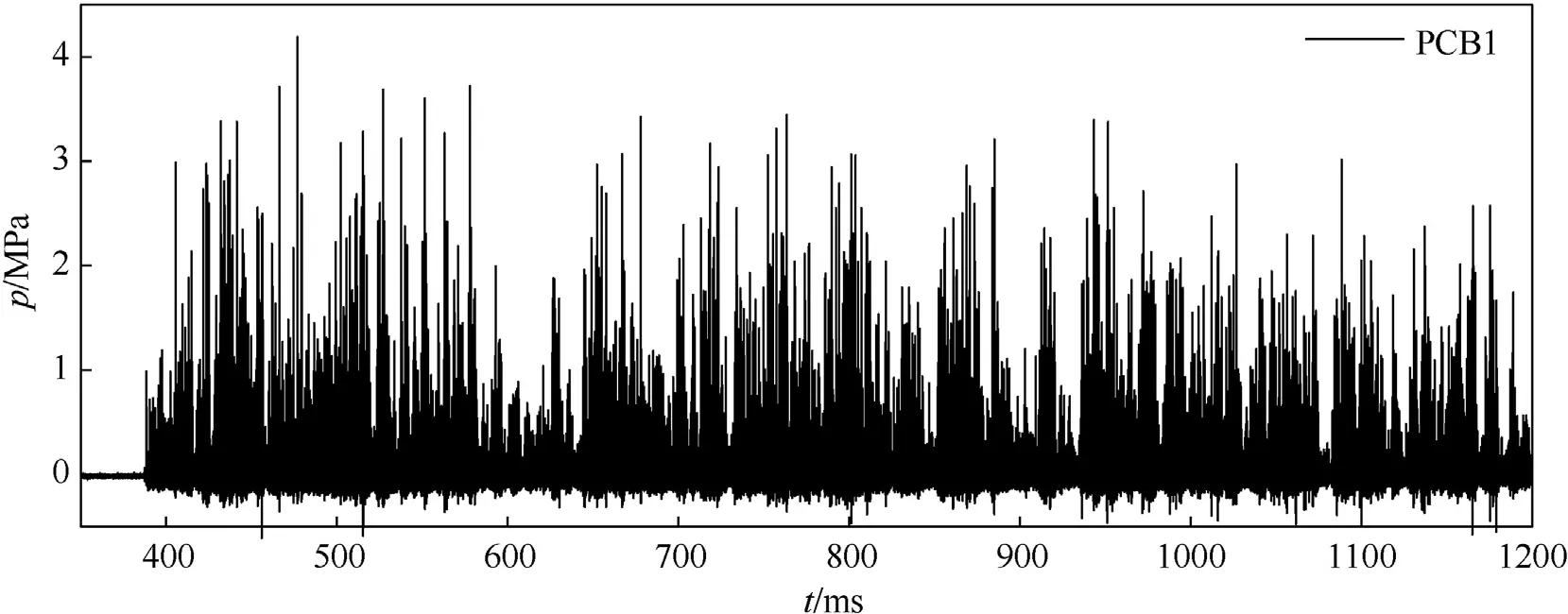
Fig.7.High-frequency dynamic pressure curve of PCB1.
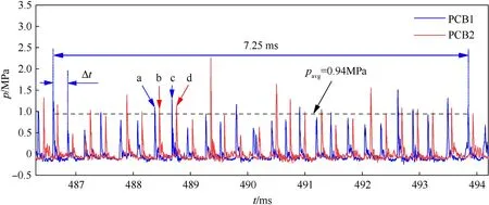
Fig.8.High-frequency dynamic pressure at PCB1 and PCB2 in single-wave propagation mode.
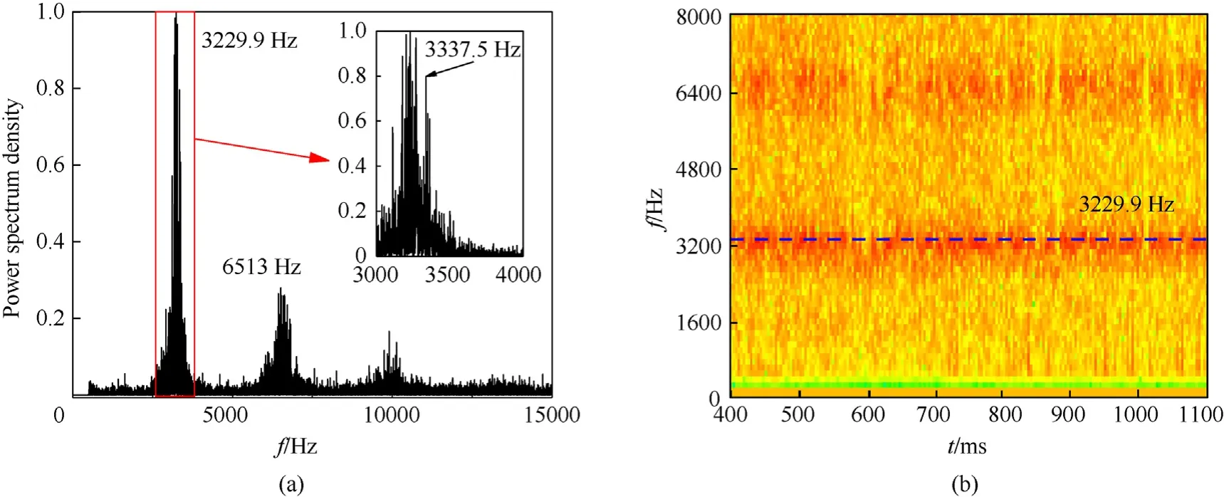
Fig.9.Frequency domain analysis diagram of RDW at PCB1: (a) FFT results;(b) STFT results.

where f is the dominant frequency.A relatively low RDW velocity was noted owing to the uneven mixing of kerosene and oxygen in the KFRG generator,which resulted in the uneven composition of the KFRG generated by the combustion.Moreover,this can be ascribed to the uneven mixing of the KFRG and oxidizer,resulting in the RDW velocity and pressure loss.
By magnifying the curve in the red box of the FFT result in Fig.9(a),a slightly lower peak can be observed at 3337.5 Hz,whose frequency was higher than the dominant frequency of 3229.9 Hz.Using Eq.(6),the average propagation velocity was 1152.8 m/s,which was equivalent to the RDW velocity in the single-wave mode with a difference of 3%.This indicates the presence of multiple propagation modes in the RDC.As the single-wave frequency was higher than the double-wave frequency,the dominant frequency corresponded to that of the double wave mode,and the subfrequency is that of the single-wave mode.Moreover,according to the power spectrum density,the detonation wave in this working condition mainly rotates following a double-wave mode with a small number of single-wave modes.After detonation,the dominant and secondary harmonic frequencies were approximately 3200 and 6400 Hz,respectively,as seen in Fig.9(b)consistent with the above analysis.
Under all conditions in this experiment,there are mainly two propagation modes of the RDW formed by KFRG,stable singlewave,and two-counter rotating waves modes.The stable single propagation wave mode is described above.The pressure peaks captured by PCB1 and PCB2 appear alternately,and the rotating direction is determined according to the occurrence order.The number of wave heads in the RDC was verified according to Eq.(5).In the two-counter rotating propagation wave mode,the pressure peak near the collision point(PCB1)was similar to that in a singlewave mode;however,the peak pressure was significantly higher.Two pressure peaks were measured at other positions(PCB2,PCB3)in each cycle,which were lower than that in the single-wave mode.
As can be seen from Fig.10,the propagation mode of the RDW is constantly transformed because of initiation,and oscillating peak pressure captured by PCB1 and PCB2 in the working period.When the peak value at PCB1 was higher,the two-counter rotating wave propagation mode and collision point were located near PCB1.Similarly,if the pressure peak at PCB2 was higher,the two-counter rotating wave propagation mode and collision point were located near PCB2.If the two pressure peak values were similar,a singlewave propagation mode was achieved.According to Eq.(5) and the PCB pressure,there was no two-codirectional RDW propagation mode,that is,two RDWs rotate and propagate in the same direction within the RDC,in this case.The two-counter detonation rotating wave propagation mode appeared frequently during the working period of the RDC,and the collision point was located near PCB1.Meanwhile,the single-wave mode propagation appeared less frequently.As shown in Fig.11,the RDW comprised a two-counter rotating wave propagation between 433.5 ms and 439 ms,which produced a high-pressure peak at the collision point of two-counter rotating waves.In addition,lower and similar pressure peaks were obtained by the RDW at the other positions.PCB1 captured a highpressure peak of 2.12 MPa,and PCB2 captured two low pressure peaks of approximately 0.3 MPa.Therefore,the collision point of the two-counter rotating waves was near PCB1.
Fig.10.High-frequency dynamic pressure curves at PCB1 and PCB2.
Fig.11.High-frequency dynamic pressure curves at PCB1 and PCB2: two-counter rotating wave propagation mode.
Fig.12.Propagation of two counter rotating waves when the collision point is located in PCB1: (a) PCB1 and PCB2 pressure curve;(b) Two-counter RDW propagation process.
The propagation process of two counter rotating waves is shown in Fig.12.In Fig.12(a),the counter rotating waves Aand Bwhich were formed after the previous cycle,collided at PCB1 at 444.7 ms when PCB1 captured a pressure peak of 2.3 MPa,which was significantly higher than that of the normal single wave.As shown in Fig.12(b),the leading shock waves of the two RDW fronts transmitted into the detonation product region of the other waves after their collision.Here,the wave degenerated into shock waves Aand B,and the wave velocity and pressure peak values correspondingly decreased.After the collision,the two transmitted shock waves continually propagated in the original direction.When fresh combustible mixtures were injected into the RDC,transmitted shock wave Breformed into RDW B.When RDW Breached PCB2 after traversing the circumference for 120,the pressure peak was 0.3 MPa.Subsequently,RDWs Aand Bcollided again at the position opposite to PCB1.Transmitted shock wave Agradually increased to Aand reached PCB2 after traversing the circumference for 60.Here,the pressure peak was slightly lower than Bbecause the transmitted shock wave was not instantly strengthened into a stable RDW after the collision process of the two waves.After the double-wave collision,the transmitted shock wave entered the post-wave reaction zone of the opposite RDW;thus,the pressure peak value of RDW in the two-counter rotating wave propagation mode was lower than that of single wave.With the exhaustion of the detonation products,the height of the fresh combustible mixture layer gradually increased.The RDW propagated to this region prior to the filling of the fresh fuel layer in the double-wave propagation mode.This consistently decreased the fuel layer height in the double-wave mode than that in the singlewave mode.Additionally,this resulted in a poor mixing process.
In a double-wave collision process,the collision point consumes the energy of the detonation wave;thus,the two-counter rotating wave propagation mode had a weak detonation state.In engineering applications,the collision propagation of RDWs should be avoided.After RDWs Aand Bcollided at 0,RDW Bpassed through PCB2 after rotating for 120,and RDW Apassed through PCB2 after rotating for 240.The two waves collided again at 0,thereby ending the double-wave propagation in the RDC for one cycle.In Fig.12(a),within one cycle,PCB1 captured the pressure peak during collision,and PCB2 captured the pressure peak when two counter rotating waves passed successively.The time intervals t,t,and tof the three pressure peaks were similar at 92,104,and 92 μs,respectively.Every interval corresponds to the time required for the RDW to rotate for 120of the RDC circumference.The blue box in the figure shows that the collision point was offset away from PCB1;hence,PCB1 captured two pressure peaks in a short time interval.In the two-counter rotating wave propagation process,the collision points of the two counter rotating waves constantly shifted.Most of the collision points in this working condition were stable at PCB1 owing to the differences in the intensity and velocity of the two waves after collision.
The propagation mode of the RDW changed from two-counter rotating wave mode to single-wave mode,as shown in Fig.13.From 478 to 479.5 ms,the collision point of RDW continuously changed at PCB1 and PCB2,and the propagation subsequently became unstable and attenuated into a deflagration wave.After 2 ms,the RDW was reformed as fresh fuel was injected into the RDC.At 481.8 ms,the two waves collided at PCB2,and PCB1 captured two lower pressure peaks,which were the two counter RDWs after the collision.In the next cycle,PCB1 captured the pressure peak of 1.2 MPa at 482.3 ms for 2/3rd of the cycle,indicating that the detonation wave has rotated for 240after collision at PCB2 and has passed through PCB1.Thereafter,a pressure peak was captured for each PCB in each cycle,indicating a single counterclockwise-rotating wave in RDC observed from the exit of the combustion chamber.Consequently,the propagation of the RDW changed from the two-counter rotating wave mode to an unstable single wave in a counterclockwise rotating mode.The propagation gradually stabilized after several cycles at 486.3 ms.During the shift of the propagation mode and after the collision of the two-counter rotating waves,a portion of the RDW entered the hot jet tube,where there was no fresh combustible mixture after ignition,eventually causing detachment and attenuation of the RDW.The attenuated RDW was completely annihilated when it collided with a strong wave that rotated counterclockwise.
The RDW propagated in a single-wave mode,as shown in Fig.14.The average pressure peak of the RDW was 0.94 MPa,which was lower than the peak pressure at the collision point in the twocounter rotating wave mode and higher than the peak pressure of each RDW.According to the time interval between the two peak points,the velocity range of the RDW propagation was calculated to be 987-1439 m/s.The velocity of the RDW remained unstable and fluctuated considerably in each cycle,which may be attributed to the uneven composition of the KFRG,and uneven mixing of the fuel and oxidant injection at the RDC head.
As shown in Fig.15,the RDW propagation mode switched from the single-wave mode to two-counter rotating wave mode at 493-506 ms.At 493 ms,the RDW propagated following singlewave mode that rotated counterclockwise as observed from the end of combustion chamber.The RDW propagated in the RDC at 494 ms,as magnified in the black box.When the RDW passed through PCB2,a pressure peak of 0.95 MPa was collected,followed by three low-pressure peaks of approximately 0.2 MPa.The product gas with high temperature behind the detonation front ignited the fresh combustible mixtures and formed three deflagration waves,which induced the RDW propagation modal conversion.In the subsequent two cycles,the three deflagration waves were gradually superimposed and strengthened to form a new RDW.The propagation mode switched into the two-counter rotating wave mode,and the pressure peak decreased.The collision point constantly varied during the modal conversion process,and the position of the collision was determined according to the high-pressure peak generated during the collision of the two waves.At 495.9 ms,the collision point was at PCB2.At 499.2 ms,the collision point changed to PCB1 until at 504 ms,when the collision point became stable and the mode conversion was terminated;the RDW mode changed from the single-wave to a stable two-counter rotating wave mode.

Fig.13.High-frequency dynamic pressure curves at PCB1 and PCB2: two-counter rotating wave mode to single-wave mode.
Fig.14.High-frequency dynamic pressure/wave velocity curves at PCB1 and PCB2: single-wave mode.
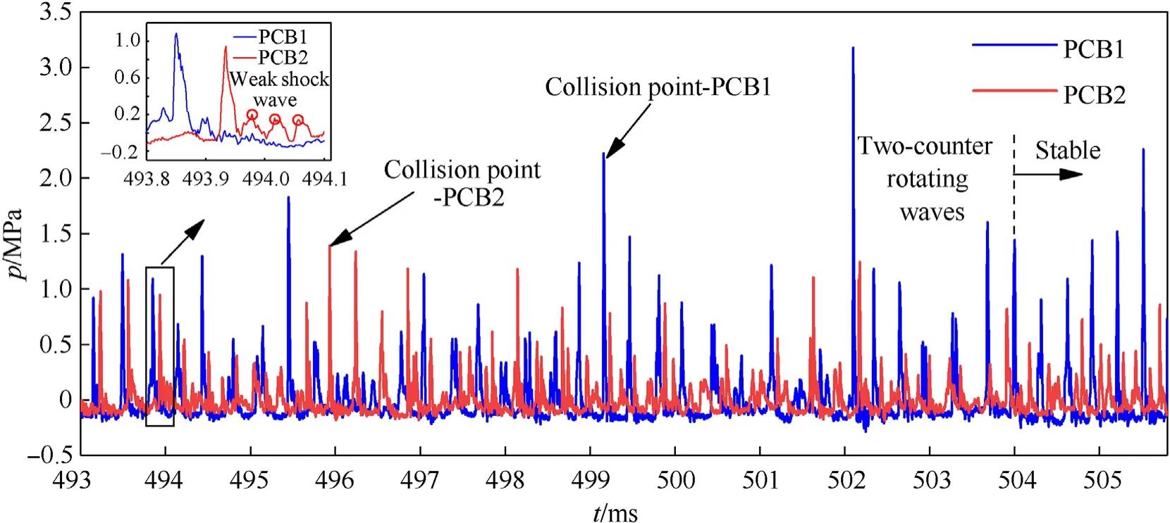
Fig.15.High-frequency dynamic pressure curves at PCB1 and PCB2: single-wave mode to two-counter rotating wave mode.
When the RDW passed through the location of the hot jet tube,multiple deflagration waves were generated owing to the RDC wall reflection and fresh combustible mixtures.During the propagation,these deflagration waves were constantly superimposed to form a reverse reflected shock wave,which gradually developed into a reverse RDW.After a period of unstable collision propagation,the single-wave mode switched to a relatively stable two-counter rotating wave mode.At 494.5 ms,the peak pressure of 1.25 MPa was captured by PCB1,and two low-pressure peak signals were captured at PCB2 in the two cycles before and after it.Therefore,the RDW propagating in the opposite direction to the original single wave was generated near PCB1,where the hot jet tube was located during injection.This confirmed the correctness of the above viewpoint.
As shown in Fig.16,the RDW propagation in the RDC at 564-581 ms underwent five stages: two-counter rotating wave,unstable mode,single-wave,unstable mode,and two-counter rotating wave modes.Throughout the RDC cycle,the RDW propagation mode was constantly switching.The instability of the RDW propagation occurred during the entire RDC operation was partly related to the decoupling and reinitiation phenomena shown in Fig.17.After the decoupling phenomenon,reinitiation was realized in a relatively short time.The detonation and reinitiation can be attributed to the detonation wave attenuated to the transmitted shock wave and high pressure at the collision area of the two waves,which blocked the injection of fresh combustible mixtures,after the collision of two waves.Furthermore,the unstable operation of the gas generator led to the uneven composition of the KFRG and unsteady mass flow rate of gas.Therefore,the transmitted shock wave in the RDC cannot be immediately enhanced into an RDW.Instead of propagating as a deflagration wave for several periods with the normal injection of the fresh combustible mixtures into the RDC,the wave underwent a DDT process and gradually reinforced to form RDW,thereby maintaining self-sustenance and stable propagation.As the generation of the KFRG and injection of the fuel oxidant in the RDC are dynamic processes,the RDW propagation process appeared as modal switching or a detonation discontinuity in the unstable mode.
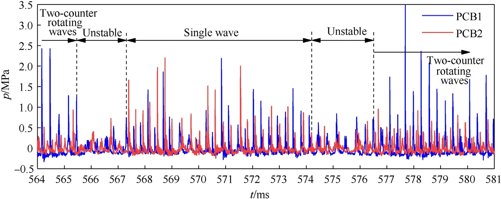
Fig.16.High-frequency dynamic pressure curves at PCB1 and PCB2: mode switching.
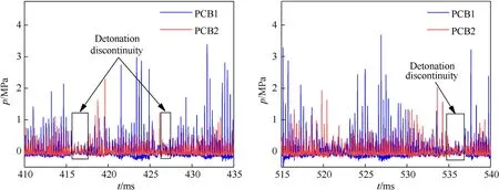
Fig.17.High-frequency dynamic pressure curves at PCB1 and PCB2: detonation discontinuity.
To eliminate errors,the experiment was repeated for case 2.The experimental results were stable under the same working conditions.The main frequencies of the RDW in the three experiments were 3249 Hz,3229.9 Hz,and 3221 Hz,respectively,and the calculated wave velocities were 1122.2 m/s,1115.6 m/s,and 1112.5 m/s,respectively.The RDW propagation modes were mixed mode with two-counter rotating waves as the main mode and single-wave as the auxiliary mode.The median value of the wave velocity was taken as the RDW propagation velocity for the followup analysis,and the fluctuations of the RDW velocity were within 0.6%.The results obtained by the experiments were stable and reproducible.
Table 4 shows the product composition and mass fraction of the KFRG after the enriched combustion.The data were calculated by the CEA software.The theoretical C-J velocity of the KFRG was calculated to be 1967.2 m/s.According to Eq.(2) and Eq.(6),the calculated RDW propagation velocity was 60.5% and 56.7% of the theoretical value,respectively.The RDW had the highest wave velocity in the single-wave mode,which greatly deviated from the calculated and theoretical wave velocity.The reasons for this deviation are as follows.First,the theoretical calculated value had anerror owing to the complex composition of KFRG.Second,KFRG had an uneven distribution owing to the combustion of the KFRG generator.Third,the uneven mixing of KFRG and oxidizer resulted in a loss in the propagation velocity and pressure of the RDW.
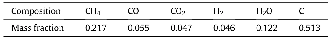
Table 4.Theoretical results of the KFRG composition.
3.2.2.Single-wave propagation mode
Based on case 10,the RDW propagated stably in a single-wave propagation mode during the experiment,and the pressure peak appeared alternately and regularly.Fig.18(a) shows the frequency diagram obtained by the FFT analysis at PCB3 with the sampling time covering the entire working process of the RDC.The dominant frequency of the RDW propagating in the RDC was 4740 Hz.According to Eq.(6),the calculated average propagation velocity of the RDW was 1637.2 m/s.Meanwhile,the theoretical RDW propagation velocity was 2048 m/s;the experimental value was 79.9% of the theoretical value,which was significantly higher than the RDW velocity in case 2.Fig.18(b) shows the STFT analysis at PCB3.The dominant frequency of the RDW propagation was approximately 4800 Hz.According to dynamic pressure and Eq.(5),RDW propagated in a single-wave mode under this condition,and the wave velocity was significantly higher than that of the two-counter rotating wave mode.
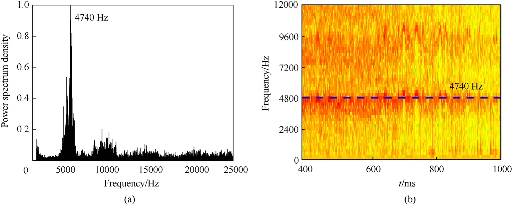
Fig.18.Frequency domain analysis diagram of the RDW in case 10: (a) FFT results;(b) STFT results.
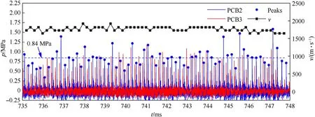
Fig.19.High-frequency dynamic pressure/wave velocity curve of PCB1 and PCB2.
Fig.19 shows the RDW dynamic pressure and velocity at 735-748 ms.The wave velocity distribution was in the range of 1644.8-1918.9 m/s,with an average value of 1768.7 m/s.This value was higher than that obtained in the FFT analysis,indicating the highly stable propagation of the RDW during this period.The average pressure peak pressure at PCB2 was 0.84 MPa.
3.3.Influence of different factors on the RDW propagation
3.3.1.Influence of the oxygen mass fraction in the oxidizer on the RDW propagation
The experiments were conducted under different conditions to investigate the influence of the oxygen mass fraction in the oxidizer on the RDW propagation.Table 1 shows the propagation velocity of the RDW with different oxygen mass fractions in the oxidizer.The RDW propagated mainly through the two-counter rotating wave mode,as indicated by the dominant frequency obtained by the FFT analysis of the dynamic pressure shows.The RDW wave velocity in this mode was calculated by Eq.(6).As shown in Table 1,the precombustion oxygen,kerosene,and air mass flow rates were fixed,whereas the oxygen mass fraction in the oxidizer was varied from 36% to 44%,and the equivalence ratio was decreased from 0.91 to 0.65.Stable continuous rotating detonation was achieved in the RDC.As the oxygen mass fraction was increased,the average propagation velocity of the RDW increased from 903.2 to 1166.8 m/s.
Fig.20 shows the dynamic pressure at PCB1 in case 1-case 3(mass flow of 36%,40%,and 44%,respectively).When the oxygen mass fraction was 36%,the delay time from the ignition of the hot jet tube to the RDW in the RDC was 20.3 ms,which was significantly higher than that when the oxygen mass fraction was 40%(2 ms) and 44% (1.6 ms).Therefore,under a low oxygen mass fraction,the initiation delay increased,suggesting the increased initiation difficulty.Under an oxygen mass fraction of 36%,the average pressure peak was only 0.3 MPa,indicating an unstable detonation mode.Thus,an increase in the oxygen mass fraction improved the activity of the combustible mixtures,which accelerated the detonation combustion reaction rate and reduced the loss of RDW velocity.The experimental results confirmed the results of existing studies [27].
3.3.2.Influence of the jet fuel mass flow rate on the RDW propagation
Table 2 shows the experimental parameters and results of the rotating detonation with the change in the kerosene mass flow rate for cases 4-10 with a fixed precombustion oxygen mass flow rate of 12 g/s,and oxygen mass fraction of 44%.As the mass flow rate of kerosene was increased from 53 to 74.6 g/s,the equivalence ratio also increased from 0.62 to 0.87,resulting in a stable RDW in the RDC.Based on the analysis of the PCB pressure and FFT results,when the equivalence ratio was 0.62-0.79,the RDW propagation mode was dominated by the two-counter rotating wave mode supplemented by single wave.When the equivalence ratio was 0.85-0.87,the RDW followed a single-wave propagation mode.The dominant frequency of the mixed and single-wave modes was employed in the FFT analysis for the wave velocity calculation of the RDW using Eq.(6).The RDW velocity distribution ranged from 1148.1 to 1637.2 m/s.As shown in Fig.21,the RDW velocity increased with the fuel mass flow rate.Under the single-wave mode,the RDW wave velocity increased substantially.When the velocity of the RDW increased with the equivalence ratio,the increase in the kerosene mass flow rate improved the velocity of RDW,which is consistent with a previous report [30].
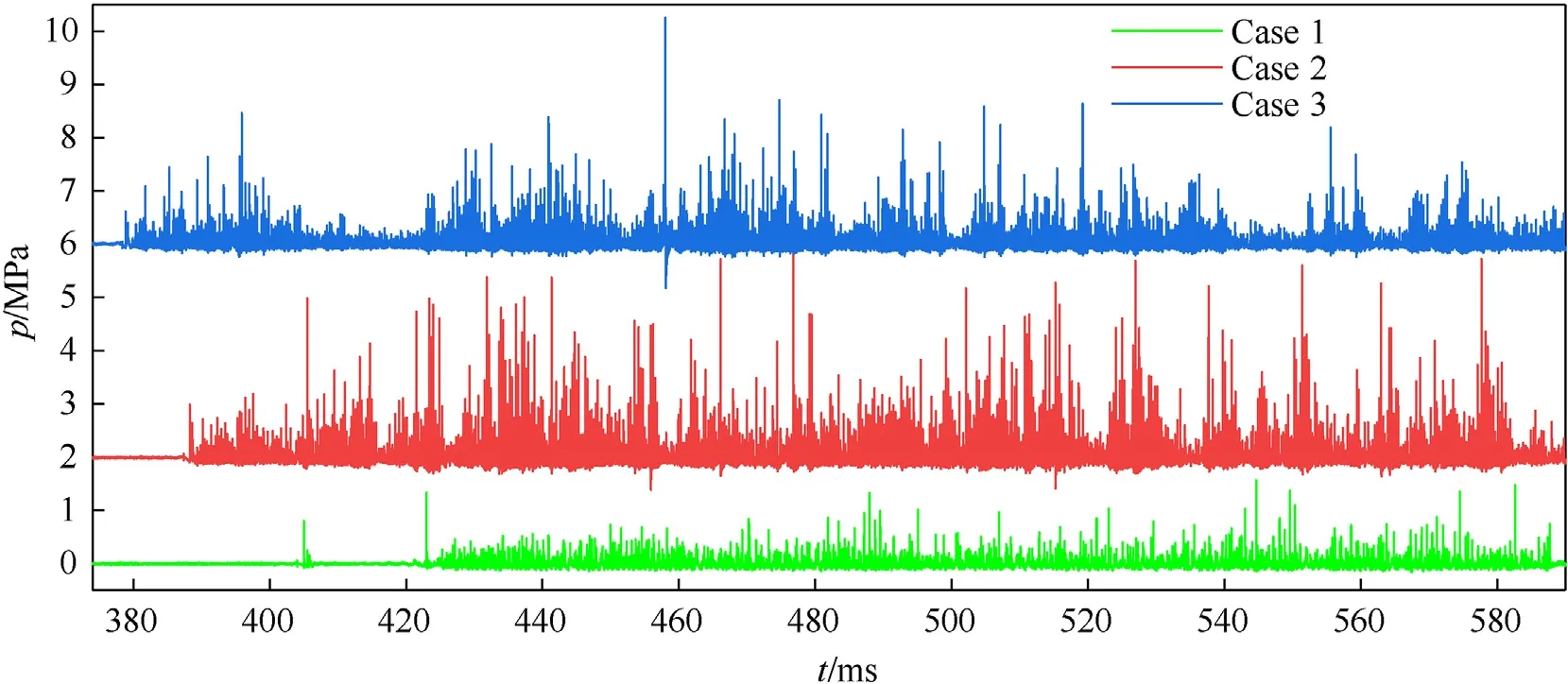
Fig.20.High-frequency dynamic pressure curve at PCB1 in case 1-case 3.
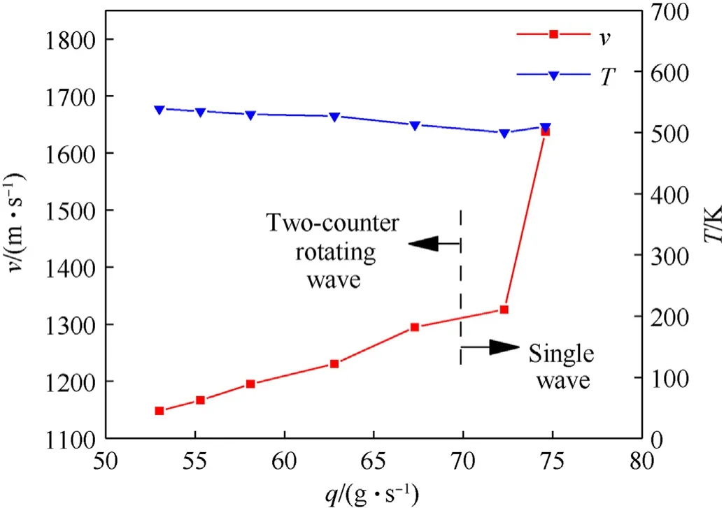
Fig.21.RDW velocity and temperature of the KFRG as a function of kerosene mass flow rate.
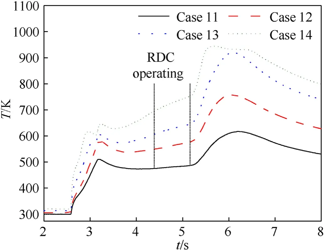
Fig.22.Temperature change of the KFRG collecting chamber.
With the increase in the kerosene mass flow rate,the temperature of the KFRG decreased slowly.This is attributed to fixed amount of heat released in the oxygen and kerosene reaction.As the kerosene mass flow rate was increased,the temperature of the product decreased.Simultaneously,the pyrolysis reaction of kerosene,which was known to be endothermic,decreased the temperature of the reaction product.Owing to the minimal temperature variation range of the KFRG,the influence of temperature can be ignored for case 4-case 10.
3.3.3.Influence of the KFRG temperature on the RDW propagation
Table 3 shows the experimental parameters and results of the RDW under different precombustion oxygen mass flow rates for cases 11-14.The temperature of the KFRG increased with the precombustion oxygen mass flow rate.In these cases,the mass flow rates of the kerosene and oxidizer were fixed,and the oxygen mass fraction was 32%.The precombustion oxygen mass flow rate increased from 12 to 21.6 g/s,the equivalence ratio decreased from 0.93 to 0.89,and the KFRG temperature increased from 480 to 725 K.
Fig.22 shows the change in temperature of the KFRG collecting chamber over time.At 2.6 s,the gas generator began to ignite.The oxygen was injected into the gas generator and reacted with the residual fuel in the combustor,causing the gas temperature in the collecting chamber to increase at 3.1 s.The kerosene was injected,and fuel-rich combustion was initiated in the gas generator.When the kerosene initially entered the gas generator combustion chamber,the temperature of the gas in the collecting chamber slightly decreased owing to the heat absorbed by the evaporation and pyrolysis of kerosene.The temperature of the gas gradually stabilized with the gas generator in a steady state.At 5.1 s,the kerosene injection ceased,and the oxygen supply was turned off sequentially.The oxidant volume increased,and the temperature briefly rose in the combustion chamber.After the oxygen was turned off,the temperature gradually decreased.
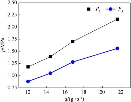
Fig.23.Pressure change curves of combustor and gas collecting chamber as a function of the precombustion oxygen mass flow rate.
Fig.23 shows the pressure curve of the combustor and KFRG collecting chamber with the change of the precombustion oxygen mass flow rate when the KFRG generator was operating.The fuel and oxidizer used by the gas generator were kerosene and precombustion oxygen,respectively.During the KFRG generator operation,the change in the kerosene mass flow rate had a weak influence on the pressure of the combustor and KFRG collecting chamber.In particular,the pressure change was only in the range of 0.8-0.9 MPa,and its influence on the gas temperature was weak.Unlike the influence of the kerosene mass flow rate on the gas generator,the change in the precombustion oxygen mass flow rate greatly affected the internal pressure.As the precombustion oxygen mass flow rate was increased from 12 to 21.6 g/s,the pressure in the combustion chamber increased from 1.18 to 2.16 MPa,and the pressure in the gas collecting chamber increased from 0.88 to 1.56 MPa.
As the temperature of KFRG was increased by increasing the precombustion oxygen mass flow rate,the composition of the KFRG varied.With the increase in temperature,the mass fraction of C decreased,which was difficult to initiate.The mass fraction of Hincreased,which was easy to initiate,thereby promoting the increase of the RDW velocity.Precombustion oxygen mass flow rate also has a great influence on the composition of KFRG from the analysis by the CEA software,as shown in Fig.24.The components with highest mass fraction in KFRG were C,whose mass fraction decreased with the increase of the precombustion oxygen mass flow rate,and CH,which also exhibited a decreasing law.CO,CO,H,and HO exhibited an increasing trend.The mass fraction of CO exhibited the most pronounced increase.The theoretical temperature of the kerosene combustion gas increased from 894 to 1000 K.
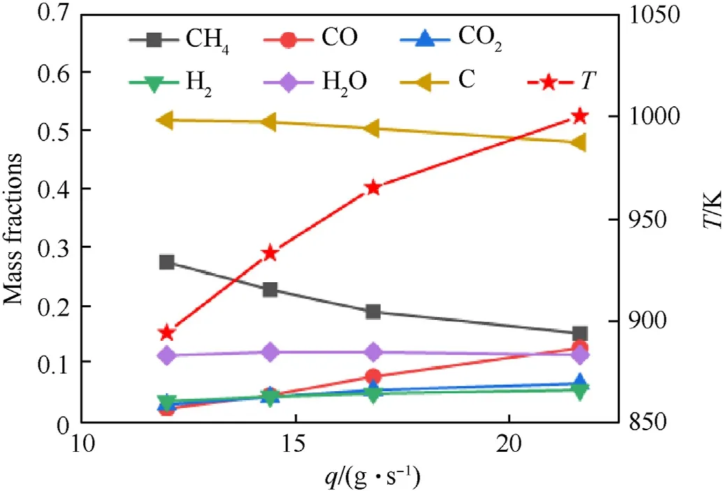
Fig.24.Theoretical composition and temperature of the product as a function of the precombustion oxygen mass flow rate.
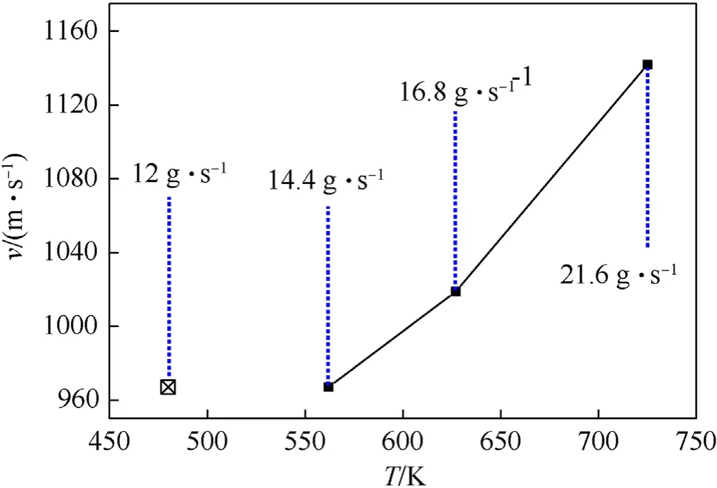
Fig.25.RDW velocity as function of the KFRG temperature.
Fig.25 shows the change in the RDW velocity with the gas temperature.In case 11,the KFRG failed to initiate,whereas in case 12-case 14,the KFRG achieved a stable self-sustaining RDW propagation.The minimum oxygen mass fraction of the RDC initiation was 32%,which was lower than the minimum oxygen mass fraction (39.2%) needed for liquid kerosene initiation [33].According to the PCB and FFT analysis,RDW propagation followed a single-wave mode.Based on Eq.(6),the wave velocity increased from 967.1 to 1141.9 m/s,indicating that the KFRG temperature had a significant influence on the RDW initiation and propagation.With the increase in the KFRG temperature,the activity of the combustible medium increased,the rate of chemical reaction accelerated,and the RDW wave velocity increased.Thus,temperature increase has a gain effect on the propagation of RDW.
4.Conclusions
In this study,the effects of the basic parameters on the rotating detonation KFRG were investigated.The following conclusions were drawn from the study.
(1) The use of KFRG as the fuel resulted in complex RDW propagation modes.The continuous switching of the single-wave and two-counter rotating wave modes was observed in most experimental conditions,and stable single-wave mode was noted in a few experimental conditions.When the oxygen mass fraction was increased from 36 to 44%,the propagation velocity of the RDW increased from 903.2 to 1166.8 m/s.When the mass flow rate of kerosene was increased from 53 to 74.6 g/s,the propagation velocity of the RDW increased from 1148.1 to 1637.2 m/s.When the equivalence ratio was within 0.62-0.79,the RDW propagation mode predominantly followed the two-counter rotating wave mode.Meanwhile,with the equivalence ratio of 0.85-0.87,the RDW followed a single-wave propagation mode.When the KFRG temperature was 480 K,the KFRG did not initiate the RDW formation.When the temperature increased from 480 to 725 K,the propagation velocity of the RDW increased from 967.1 to 1141.9 m/s.
(2) When the kerosene mass flow rate was 57.1 g/s,the gas generator oxygen mass flow rate was 12 g/s,the oxidant mass flow rate was 594.6 g/s,the oxygen mass fraction was 40%,and the equivalence ratio was 0.76.Thus,a stable RDW with a dominant two-counter rotating wave mode and auxiliary single-wave mode was obtained.The main frequency and velocity of the RDW were 3229.9 Hz and 1115.6 m/s,respectively.Correspondingly,when the kerosene mass flow rate was 74.6 g/s,the gas generator oxygen mass flow rate,oxidant mass flow rate,oxygen mass fraction,and equivalence ratio were 12 g/s,646.6 g/s,44%,and 0.87,respectively,thereby a stable single-wave propagation mode was obtained.The main frequency of this RDW was 4740 Hz,and its propagation velocity was 1637.2 m/s.
(3) The initiation of KFRG cannot be achieved with low oxygen mass fraction and KFRG temperature of KFRG.The propagation velocity of the RDW can be improved by increasing the oxygen fraction in oxygen-rich air,kerosene mass flow rate,and temperature of KFRG.Compared with liquid kerosene,KFRG can achieve rotating detonation at a lower oxygen mass fraction of 32%.
This study investigated the RDW propagation mode of KFRG,and its factors.Further research need to be carried out to study the influence of the geometric structure of the CRDE on RDW,which will lay a foundation for the engineering research of the rotating detonation engine.Further,the KFRG composition should be determined,and its effects on the RDW propagation should be analyzed in detail.The RDW propagation modes should be investigated with high-speed photography.Moreover,it is necessary to optimize the structure of the CRDE and explore the limit working range of it,the detonation methods at lower oxygen levels and even air conditions should be investigated.
The authors declare that they have no known competing financial interests or personal relationships that could have appeared to influence the work reported in this paper.

- Defence Technology的其它文章
- Adaptive robust control for triple avoidance -striking -arrival performance of uncertain tank mechanical systems
- Experimental study on WFeNiMo high-entropy alloy projectile penetrating semi-infinite steel target
- Numerical investigation of a muzzle multiphase flow field using two underwater launch methods
- Shock wave and bubble characteristics of underwater array explosion of charges
- A micro-chip exploding foil initiator based on printed circuit board technology
- On the higher-order thermal vibrations of FG saturated porous cylindrical micro-shells integrated with nanocomposite skins in viscoelastic medium