
Numerical simulation and experimental research on an inductively coupled RF plasma cathode
2022-02-15 11:08:20ZongqiXU徐宗琦PingyangWANG王平陽ZhiweiHUA華志偉ShiyuanCONG從拾源andShengnanYU余盛楠
Plasma Science and Technology 2022年1期
關(guān)鍵詞:平陽
Zongqi XU (徐宗琦), Pingyang WANG (王平陽), Zhiwei HUA (華志偉),Shiyuan CONG (從拾源) and Shengnan YU (余盛楠)
1 Institute of Engineering Thermophysics, School of Mechanical Engineering, Shanghai Jiao Tong University, Shanghai 200240, People’s Republic of China
2 Key Laboratory of Materials Modification by Laser, Ion and Electron Beams (Ministry of Education),School of Physics, Dalian University of Technology, Dalian 116024, People’s Republic of China
Abstract In this study,numerical simulation and discharge current tests were conducted on an inductively coupled radio frequency (RF) plasma cathode.Numerical simulations and experimental measurements were performed to study the factors influencing the electron extraction characteristics, including the gas type, gas flow, input power and extracting voltage.The simulation results were approximately consistent with the experimental results.We experimentally found that the RF input power mainly determines the extracted electron current.An electron current greater than 1 A was acquired at 270 W (RF input power), 2.766 sccm(xenon gas).Our results prove that an inductively coupled RF plasma cathode can be reasonable and feasible, particularly for low power electric propulsion devices.
Keywords: RF discharge, RF plasma cathode, electron extraction characteristics, RF power,electron current
1.Introduction
Cathodes are important structural components primarily used in electric propulsion applications to deliver an electron beam,particularly in Hall thrusters and ion thrusters.For example,cathodes restrict the lifetime of thrusters and determine whether satellites can complete space missions optimally.An object or a device that can emit electrons is called a neutralizer.Based on different electron emission principles,neutralizers can be divided into hot cathode, hollow cathode,and plasma cathodes, for example, radio frequency (RF)plasma cathode and electron cyclotron resonance (ECR) discharge cathode [1].
A hot cathode generally refers to a pure metal that emits electrons at a high temperature, with the advantages of stable emission, resistance to high-pressure ion bombardment, and lack of reactivation required after atmospheric exposure.Tungsten is typically used as an electron emitter owing to its high melting point,low work function,high emission and low evaporation rate.However, it can not only be processed into filaments or bands, but can also chemically react with oxides at high temperatures.With the development of science and technology, hollow cathodes [2] with thermionic emitters made from low-work-function materials (e.g.LaB6) or composites (e.g.porous tungsten impregnated with a low-workfunction composite of barium oxide, calcium oxide, and aluminum oxide) are being extensively used in plasma propulsion owing to their high current densities and low cathodefall voltage [3].However, some issues associated with the hollow cathodes have seriously affected their utilization,such as difficulty in acquiring the insert material, considerable amount of time required to preheat before operation and cooling after operation, discharge oscillation due to temperature drop [4], low electron release efficiency of the emitter during operation and poor resistance to poisoning.Therefore,hollow cathodes have the characteristics of high production cost, limited service lifetime and delayed ignition process.In recent years,there have been significant efforts on developing other electron sources as practical alternatives, while plasma cathodes have attracted much attention.Different plasma methods such as RF (capacitively coupled plasma [5] or inductively coupled plasma (ICP)) [6], micro-wave ECR)[3, 7, 8], and helicon [9, 10] have been employed in plasma cathode devices.Among plasma cathodes, microwave and helicon neutralizers are equipped with a complicated electron extraction device and require an external magnetic field that consumes additional power.Conversely, RF excitation is considered a preferable plasma generation method for cathode applications owing to its characteristics of simple structure,low-power loss and high plasma density, particularly in the ICP discharge mode [11].
Inductively coupled RF plasma cathode has been the focus of research for more than a decade both theoretically and experimentally.Watanabe et al [12] designed an ICP cathode for ion thrusters and presented a series of experimental studies on its performances.The emission electron current reached approximately 2.1 A with an RF power of 100 W, Xe mass flow rate of 2 sccm, and target voltage of 40 V.Subsequently,an emission electron current of 3.3 A was obtained in a combination test involving an anode-layer-type Hall thruster and an RF plasma cathode [13, 14].They also found a balance between the performances of plasma ignition and electron emission and determined the discharge vessel diameter [15].Scholze et al described the design of an inductive coupled RF plasma bridge neutralizer with a maximum electron current of 1.6 A at a Xe gas flow rate of 0.2 sccm and a power of 300 W [16].They developed a performance model to calculate the electrical parameters and provided the optimization ideas[17].Godyak et al[3]found that in the RF plasma discharge experiments, the maximum emission efficiency of the ICP was higher than that of microwave and helicon.Other studies concerning the RF ignition of hollow cathodes can also be found in their papers[18–20].Jahanbakhsh et al discussed the relationship between the electron extraction capacity and the gas flow rate,the size of the extraction aperture, and the absorbed RF power[10, 21].According to another theory, the anode spot has an impact on the electron extraction property [22, 23].A comparison of numerical and experimental results showed that the effects of target voltage, aperture diameter, gas flow rate and RF power were consistent [24].In addition, a ferromagnetic core was utilized for enhancing the power transfer efficiency of ICP by the Bogazici University Space Technologies Laboratory[25].Another corrosive gas,such as iodine vapor,was also considered as the working gas in the RF cathode [26, 27].
However,there are no investigations on the ion collectors which have an important influence on the electron extraction.In this study, we designed a type of inductively coupled RF plasma cathode with a cylindrical ion collector and analyzed the influences of the gas flow rate,RF power and bias voltage on the current extraction through simulations and experiments.In section 2, we describe the characteristics of the inductively coupled RF plasma cathodes in detail.Section 3 provides the description of a geometric model and presents results and discussion of the numerical simulations.Section 4 describes the experimental setups and presents the experimental results and corresponding discussions.Finally, in section 5, we summarize our findings and compare the two results.
2.Inductively coupled RF plasma cathode
Figures 1 and 2 show the RF plasma cathode designed for this investigation.The plasma chamber for the discharge is made into a cylindrical structure, and its inner diameter and length are 40 mm and 76 mm,respectively.The wall of the discharge chamber is made of alumina, which has the properties of insulation and high temperature resistance.The orifice plate is made of graphite and there is a 2 mm diameter orifice at the center of the plate for electron emission.Considering the skin effect of high-frequency transmission current, a 5 mm diameter copper pipe is wrapped around the discharge chamber as the induction coil.The cylindrical collector made of graphite is placed on the axis of the discharge chamber as an ion collector, and it has six small holes whose diameter is 1 mm along the periphery for gas to flow into the chamber.
Because the ignition of ICP obeys Paschen’s law, the orifice diameter is much smaller than the inner diameter of the chamber,and this helps sustain a sufficiently high pressure in the RF plasma cathode for the self-ignition of plasma.To maintain quasi-neutrality in the ICP discharge, an equivalent quantity of ions should be collected at the ion collector in the cathode when electrons are emitted from the orifice.Thus, a graphite collector, which is inserted into the chamber, is necessary for the steady operation of the RF plasma cathode.The shape of the ion collector has an important influence on the ion collection ability and further determines the values of the emitted electric current.
3.Method, results, and discussion of numerical simulations
3.1.Solution strategy
In this study, a 2D geometric model is employed to investigate the RF plasma cathode with xenon gas.Three coupled processes are considered in the model: particle transport,neutral gas flow and electromagnetic induction.They are described by typical drift-diffusion approximation equations,a set of N–S equations and Maxwell equations, respectively.A series of assumptions is made as follows to simplify the analysis.
(a) The induction currents are solved in the frequency domain.
(b) The electron energy distribution function (EEDF) is assumed to obey the Maxwellian distribution.
(c) The working gas is considered as an ideal gas.It is governed by the state equation and compressible.
(d) Because of the effective energy exchange between ions and neutral particles, their temperatures are equal.
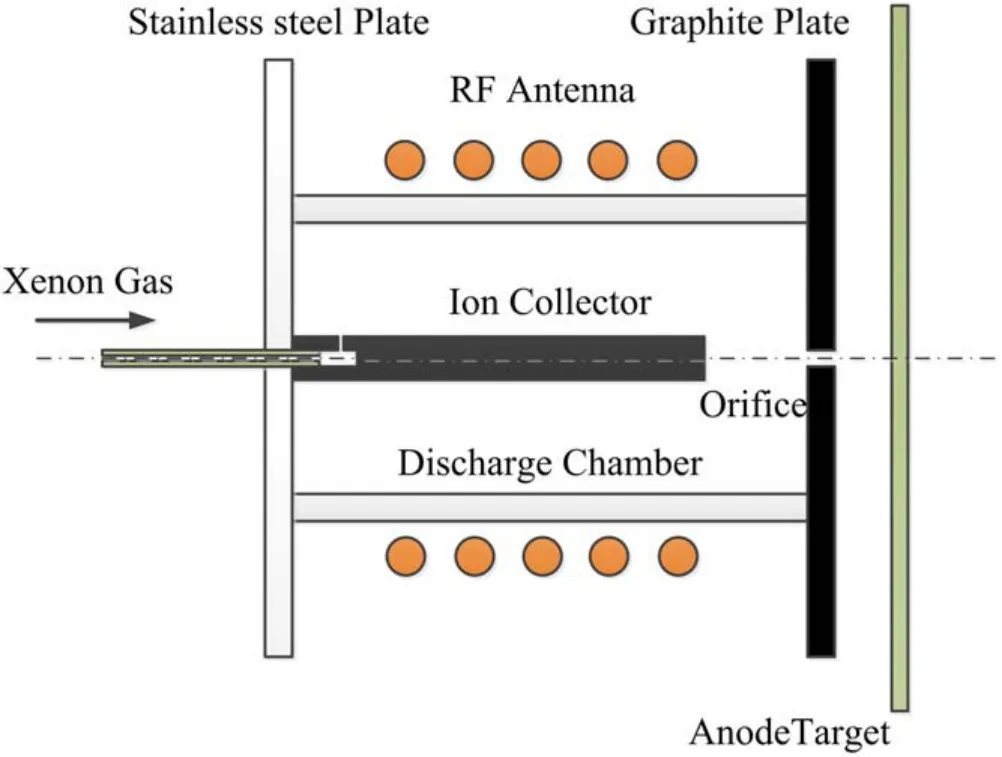
Figure 1.Schematic of RF plasma cathode.
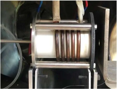
Figure 2.Side view of RF plasma cathode and target.
(e) The effect of a self-induced electromagnetic field is negligible
(f) The electronically excited xenon species are lumped into a single species.
The equations and boundary conditions are presented in the following subsections and solved numerically using the finite element method and the standard Galerkin method for space variation and back differentiation method for time variation.The commercial software package COMSOL Multiphysics is employed as the solver, which has been successfully demonstrated to be applicable for simulating gas discharge processes [28–30].Triangular and boundary layer meshes are employed in this model.To obtain a fast convergence of the calculation,the particle transport equations are discretized in a logarithmic form using the linear Lagrange shape function.To accelerate the model convergence, a transient solver is employed and the quasi-steady results are discussed [31].
3.2.Governing equations
Based on the aforementioned assumptions, the transport processes of the electrons and heavy particles are described by typical drift-diffusion approximation equations.The electron and electron energy transport equations are as follows[32]:
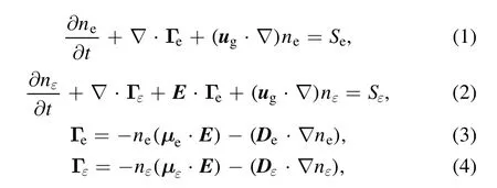
whereneandnεare the electron number density and electron energy density, respectively (i.e.nε=ne,whereis the mean electron energy, and the electron temperature isTe= 2εˉ3); Γeand Γεare respectively the el ectron flux and electron energy flux;eμandμεare,respectively, the electron mobility and electron energy mobility;DeandDεare,respectively, the electron diffusion coefficient and electron energy diffusion coefficient.According to the assumption of the Maxwellian distribution of the EEDF, the mobility and diffusion coefficients satisfy Einstein’s relationship, i.e.με=5μe3,De=μeTe,Dε=με Tε.Therefore, only the electron mobilityeμis required to be solved by the Boltzmann solver (i.e.BOLSIG+) [33].The collision source termSerepresents the production or loss of electrons, and the electron collision reactions with the heavy particles are summarized in table 1.The energy source termSεrepresents the complete energy change in the entire collision reaction.ugis the flow velocity of the neutral gas, andEis the electric field intensity.SeandSεare described as follows:
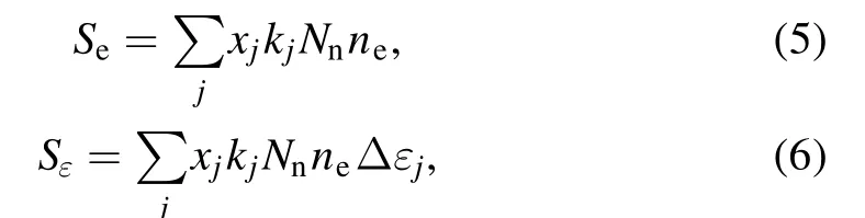
wherexjis the mole fraction of the species for reactionj;kjis the rate coefficient,calculated by the Boltzmann solver;Nnis the total number density of the neutral particle;jεΔ is the energy loss from the reactionj.
The heavy particles also have a similar transport equation as follows [31]:
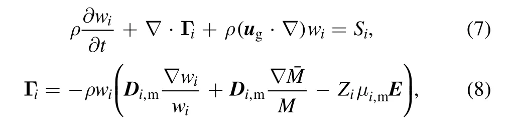
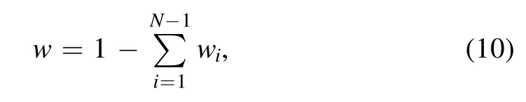
where ρ denotes the mass density of the working gas;wiis the mass fraction of the ith species;Siis a collision term of the heavy particles derived from the plasma chemical reactions in table 1;iΓ is the flux of the ith species,i,mμandDi,mare,respectively, the average mobility and diffusion coefficients of the ith species;Ziis the charge number of the ith species.The subscript m refers to the average over all components of the mixing working gas, including ground atoms, excited atoms,and ions.Moreover,Mˉ refers to the mean molar massof the mixing working gas [31], expressed as follows:
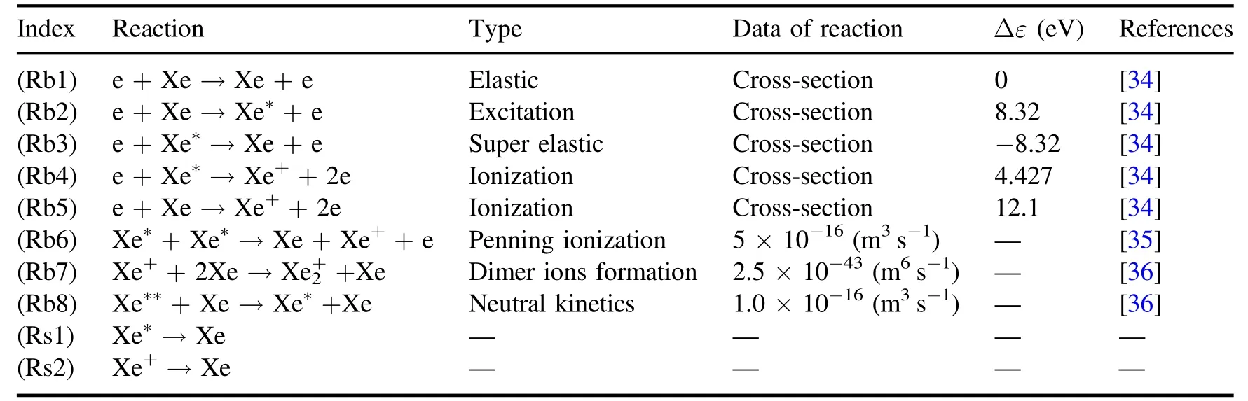
Table 1.Plasma chemistry processes used in the model.
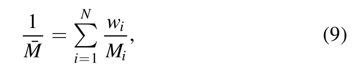
where N is the total number of species in the gas mixture;Miis the molar mass of the ith species.Among them, the state atom has the maximum proportion, and the mass fraction expression is
The electric field intensity is calculated by combining the particle transport equations with Poisson’s equation [31]
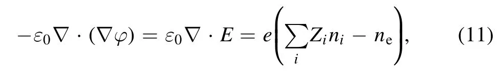
whereφ,ε0,ni,and e denote the plasma potential,permittivity of vacuum, ion number density, and elementary charge,respectively.
3.3.Gas flow equations
The flow of the neutral gas in the calculation domain is considered a laminar flow model, which is described by a set of N–S equations.The continuity and momentum balance equations are given as follows [37]:
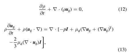
where p is the absolute pressure of the gas mixture;dμis the dynamic viscosity; I is the unit tensor.The pressure gradient force and viscous stress tensor are on the right-hand side of equation (13).The superscript T represents the matrix transposition.
3.4.Electromagnetic induction equation
For the nonmagnetized and nonpolarized plasma, the induction currents are computed in the frequency domain using the following equation:

Here, jkis the imaginary part(i.e.j2
k= ?1);ωis the angular frequency; A is the magnetic vector potential;0μis conductivity of vacuum.The plasma conductivity should be specified as a material property, typically from cold plasma approximation:
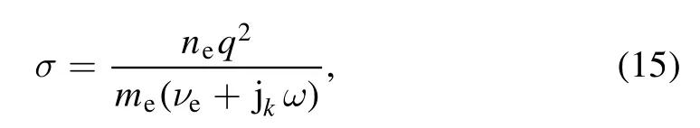
where q is the electron charge;meis the electron mass;eνis the collision frequency.
3.5.Geometric model description and boundary conditions
Because the designed cathode is symmetrical about its central axis, the calculation domain can be set one-half of its cross section.As detailed in figure 3, domain d.1 is the anode target; domain d.2 is the RF cathode wall; domain d.3 is the collector; domain d.4 is the RF antenna; boundary b.1 is the gas inlet; boundary b.2 is the plasma outlet; boundary b.3 is the inner wall;b.4 is the symmetric axis along the direction of z-axis; b.5 is the collector wall; b.6 is the anode target wall.The length and radius of the discharge chamber along the axis are 80 mm and 20 mm, respectively.The thickness is 4 mm.The gap between the anode target and the RF cathode tip is 10 mm.The length and width of the calculation domain are 104 and 55 mm.The diameters of the gas inlet and plasma outlet are respectively 1 mm and 2 mm.
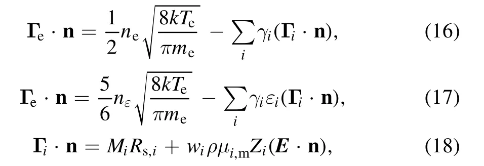
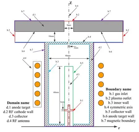
Figure 3.Geometric model of RF plasma cathode.
The fluxes of the electron, electron energy, and heavy particle have boundary conditions as follows [31]:where n is the normal direction of the boundaries; k is the Boltzmann constant;Teis the electron temperature;iεis the mean energy of the secondary electrons;iγis the secondary electron emission coefficient, which is determined by the incident ions and material surface properties.In our study,only the secondary electron emitted from the collector surface was considered because the ion bombardment dominantly occurs on the collector wall.Therefore, an empirical value= 0.25was set.Rs,idetailed in [38] is the rate of surface reaction on the wall in the first term on the right side of equation (18), and the second term is the ionic migration on account of the electric field acting toward the wall, which is satisfied if the expressionZ i(E·n) > 0.The collector is grounded, i.e.φ= 0,and the anode is connected to a power supply of which the detailed expression is as follows [31]:
whereJi,Je,andJdare, respectively, the current densities of the ion,electron and displacement,respectively;Idis the total discharge current applied to the anode target boundary.The symbol Ω refers to the integral boundary on it,and the surface area of the anode target will be automatically calculated after a symmetric rotation.
For the gas flow equations,the collector surface and inner wall are considered as no-slip condition.The gas inlet and gas outlet respectively have mass flow rate and fixed-pressure boundary conditions.For the electromagnetic induction equation,the normal direction of the calculation boundaries is parallel to that of the magnetic vector potential.The other boundaries in the calculated domain satisfy Maxwell’s equations.Table 2 presents all the boundary conditions.
3.6.Characteristics of plasma parameters
The RF power supply drives the antenna coil, external to the plasma and separated from it by the cathode wall.The RF current flowing in the coil launches an evanescent disturbance that decays over a distance of centimeters into the plasma[39].This induces RF current in the plasma and transfers energy to electrons.The plasma discharge is sustained after the RF electromagnetic is coupled with the electrons in the plasma.The energy transfer phenomenon is called ohmic heating or collisional heating [39].In low-pressure inductively coupled RF plasma additional electron heating mechanism exists that is collisionless heating, which is dominant due to the too low collision frequencies for efficient ohmic heating of electrons [40, 41].The heated electrons react with neutral particles by elastic, ionization, and excitation collisions.
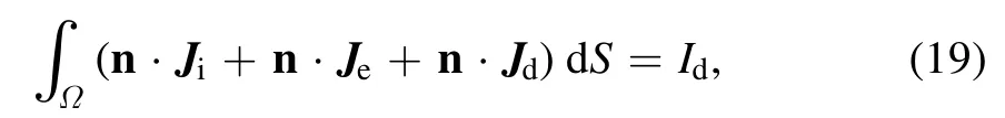
The RF current in the antenna also generates a weak induced magnetic field along the axial direction, which has a significant impact on the parameter distributions of the charged particles in the discharge chamber.Figure 4 shows the magnetic field profiles.
The maximum magnetic flux density appears in the central region near the RF coil, as shown in figure 4, where most of the electrons are trapped and the neutral particles have a high ionization rate.
The distributions of the various plasma parameters in the discharge chamber are acquired through numerical simulation,which is helpful for analyzing the performance of the RF plasma cathode.The main simulation conditions are as follows: xenon gas flow rate is 5 sccm; extracted voltage is 100 V;RF power is 100 W.Figure 5 shows the distribution of electron number density.The figure shows that the maximum electron number density occurs near the outlet of the discharge chamber and the induction coil,and the value is above 2.5 × 10¹⁸m?3.As mentioned before, this is because the electrons are bound in the central region of the discharge chamber by the induced magnetic field.Moreover, the electrons are also attracted by the anode target and emitted from the outlet of the discharge chamber.This indicates that a high plasma density can be acquired by ICP discharge; thus, sufficient electrons can be produced and extracted to form an electric current.
Figure 6 shows the electric potential distribution.Clearly,the potential changes sharply near the collector.Since the collector is biased negatively, a large potential gradient is more helpful for ions to be absorbed.The electric potential is maintained at approximately 100 V between the discharge chamber and the anode target.The electrons can be easy to be extracted under a potential condition.
3.7.Extracted current characteristics
Figure 7 presents the response time of the extracted current between the anode target and the collector.As shown in the figure, the current becomes stable in a short time, and the value is approximately 0.3369 A.This result indicates that thedesigned structure of the RF plasma cathode meets the requirement of acquiring a stable extracted current.

Table 2.Boundary conditions of model.The numbers (b.1–b.7) indicate the boundaries shown in figure 3.
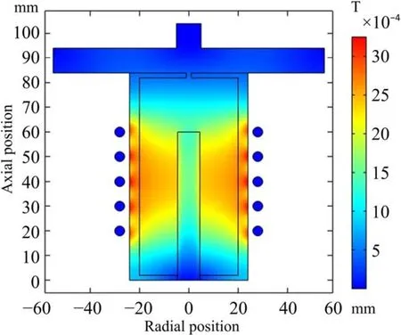
Figure 4.Distribution of the magnetic flux density in the calculation domain.
Figure 5.Distribution of the electron number density in the calculation domain.
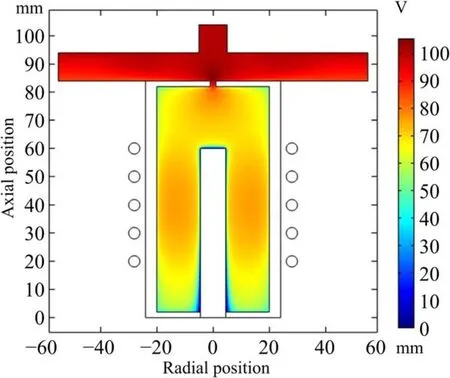
Figure 6.Distribution of the electric potential in the calculation domain.
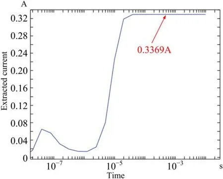
Figure 7.Response time of extracted current.
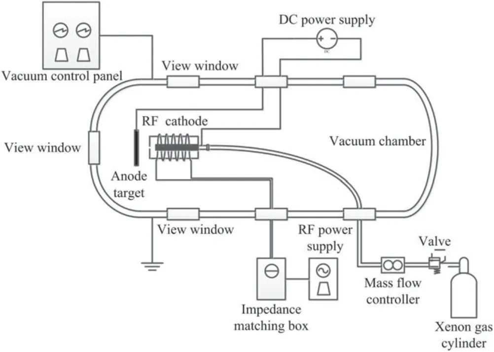
Figure 8.Experimental system of RF plasma cathode.
4.Method, results, and discussion of experiments
As described above, the operation of the RF plasma cathode comprises two parts: plasma generation and electron extraction.Experimental studies have been conducted to determine the relationships between the electron extraction and gas flow rate, RF power, and bias voltage.The mass flow controller used in the experiment is M3030 V/A (N2equivalent).The gas factor corresponding to Xe is 1.383.The experimental parameters are set as follows: the gas flow reading of the controller varied from 2.0 to 4.0 sccm at intervals of 0.5 sccm,and the RF input power varied from 50 to 300 W at intervals of 10 W.The bias voltage varied from 0 to 100 V at intervals of 10 V, and the electron current extracted by the target is measured.
4.1.Experimental setup
Figure 8 shows the experimental system.All the experiments are conducted in a vacuum chamber, whose diameter and length are 0.6 m and 1.2 m, respectively.The vacuum chamber reaches approximately 1.0 × 10?4Pa without any load using two turbo-molecular pumps and two rotary vane pumps.The RF cathode and the anode target are placed in the chamber, whereas an RF generator, an impedance matching box,and a DC power supply are attached from outside of the vacuum chamber.The anode target is located approximately 10 mm downstream of the orifice plate.The anode target and ion collector are biased positively and negatively by the DC power supply, respectively.The potential drop between the ion beam and the neutralizer in the actual operation is simulated by that between the ion collector and the anode target in the experiment.
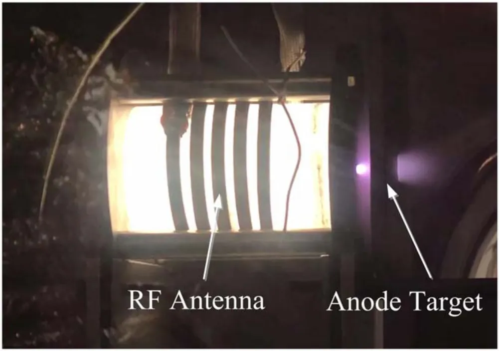
Figure 9.Image of RF plasma cathode at an PF power of 200 W,Xe mass flow rate of 2.5 sccm, and a bias voltage of 50 V.
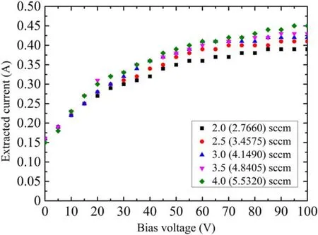
Figure 10.Current–voltage characteristics of RF cathode of an RF input power of 100 W.
The neutral xenon, which is employed as the propellant,is fed into the discharge chamber via the mass flow controller for cathode ignition.The induction coil is connected to the RF generation through the impedance matching box,in which the matching network reduces the reflected power to maximize the input power to a load.The xenon gas is coupled by the RF electric field, which is generated in the circumferential direction inside the coil,and finally,plasma is produced.The skin depth is low due to the high frequency (13.56 MHz).
When the plasma plume supplies electrons to the anode target, the extracted electron current rapidly appears in the circuit.Figure 9 shows the image of the device under operation.As shown in the figure, the extracted electron current has a maximum value near the outlet of the discharge chamber.
4.2.I–V characteristics
Figure 10 shows the current–voltage characteristics of the RF plasma cathode when the RF input power is 100 W.After the ignition of the ICP, a current of approximately 0.16 A is generated with no bias voltage.The extracted current increases quickly when the bias voltage varies from 0 to 50 V and is maintained nearly constant beyond 85 V.As the voltage is increased, the extracted electrons are accelerated to ionize the Xe atoms, and a plasma plume is formed betweenthe cathode and anode target.The electron current is built after the target absorbs electrons from the plasma plume.The upper limits of the extracted electron current are observed at different Xe mass flow rates.
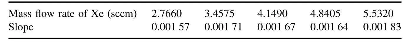
Table 3.Slopes of the fitted line in the bias voltage range of 30–85 V.
Figure 10 reveals that the extracted current increases with the variation in the mass flow rate from 2.0 to 4.0 sccm (Xe,2.7660–5.5320 sccm) at a constant RF power.However, the variable quantity of the extracted current ΔI decreases at the same mass flow rate.As shown in figure 10, the whole extracted currents have an almost linear behavior in the bias voltage range of 30–85 V.The values of the slopes are acquired via a linear fit.Table 3 presents the results.In addition,as the bias voltage increases further above 85 V,the extracted current remains nearly a constant.
As listed in table 3, the slopes are similar in the mass flow rate range of 3.4575–4.8405 sccm.This means that the growth rates of every extracted current are almost consistent.The minimum and maximum slopes correspond to the minimum and maximum mass flow rates of Xe, respectively.It is inferred that a small amount of gas is not conducive for increasing the increment of extracted current, which albeit increases rapidly after the gas flow rate reaches a certain value.
4.3.RF power and mass flow rate
Figure 11 shows the electron current extracted by the target as a function of the RF input power and mass flow rate (target voltage = 50 V constant).The cathode achieved approximately 0.18 A with 50 W of RF input power, and over 1 A with 260 W,2.0 sccm(Xe,2.7660 sccm).The stability of the cathode is tested for over an hour period.The result shows that after an initial automatic adjustment of matching network for some minutes,the electron current is constant without any change in the matching.
Figure 11 reveals that at constant bias voltage, by increasing the RF power from 50 to 300 W, the extracted current increases.However, the variable quantity of the extracted current ΔI decreases at a bias voltage of 50 V.As shown in figure 11, the whole extracted currents have a largely linear behavior in the RF power range of 80–260 W.The value of slope is approximately 0.003 89 via a linear fit.In addition,as the RF power increases further above 260 W,the extracted current is saturated.
5.Conclusion
Numerical and experimental parametric studies were conducted to investigate the effects of the gas flow rate, RF power and bias voltage on the plasma generation and electron extraction performance of an RF plasma cathode device.
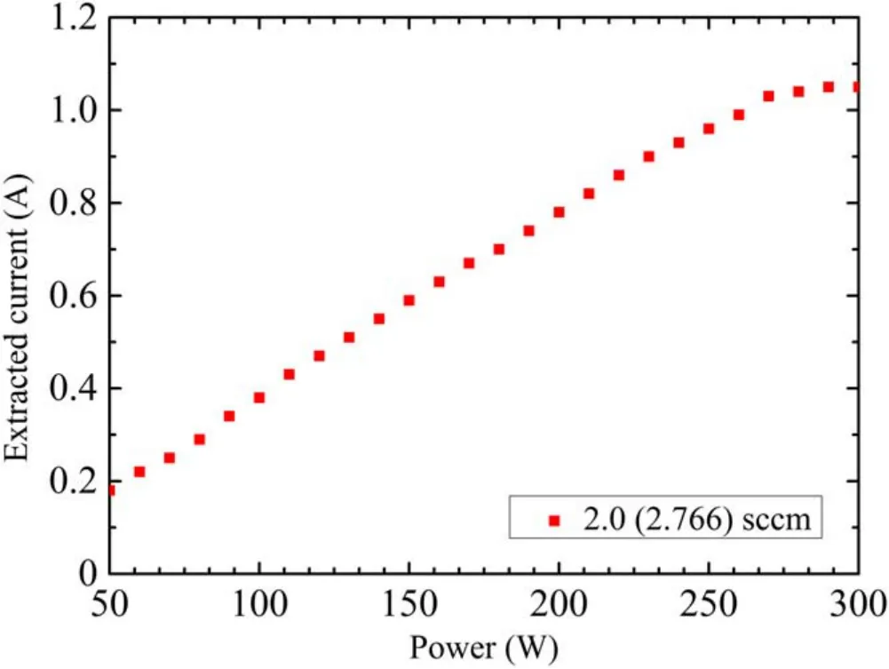
Figure 11.Current–power characteristics of RF cathode at a bias voltage of 50 V.
A comparison of figures 7 and 10 shows that the extracted current is approximately 0.34 A under the condition of 5 sccm Xe,100 V bias voltage and 100 W RF input power in the numerical simulation.In addition, in the experimental result, limited by the mass flow controller, the extracted currents are 0.43 A and 0.45 A at approximately 4.84 sccm Xe and 5.53 sccm Xe,respectively,with the other conditions kept the same.It can be considered approximately 0.44 A at 5 sccm in the experimental measurement.Therefore, compared with the experiment, the relative error in the simulation is approximately 22.7%.This is due to the low plasma density obtained in the simulation software during the low-pressure calculation.The presented experimental and simulated results are approximately consistent.
As shown in figure 11, an extracted current of 1.03 A from the cathode is achieved using 2.766 sccm xenon,270 W of RF input power at 13.56 MHz, and 50 V DC bias on the anode target.Increasing gas mass flow rate was conducive for increasing the extracted current.For the bias voltage and RF power,similar results were obtained.Moreover,the extracted current seems to have a limit value.
An RF plasma cathode is feasible as an electron source for electric propulsion devices.The optimization design of the cathode will be part of future work for further performance enhancement, as a replacement for the hollow cathodes.
Acknowledgments
This work is supported by Joint Fund for Equipment Preresearch and Aerospace Science and Technology (No.6141B061203).
ORCID iDs
猜你喜歡
Plasma Science and Technology(2022年7期)2022-08-01 11:34:02
Plasma Science and Technology(2022年7期)2022-08-01 11:33:42
東坡赤壁詩詞(2020年2期)2020-06-04 15:44:10
邊疆文學(2020年5期)2020-05-22 02:58:58
科學之友(2020年4期)2020-05-19 15:13:02
西夏研究(2020年1期)2020-04-01 11:54:40
中國三峽(2017年9期)2017-12-19 13:27:43
中華戲曲(2016年2期)2016-01-22 08:18:55
中國醫(yī)療美容(2015年4期)2015-04-27 02:24:03
溫州職業(yè)技術(shù)學院學報(2014年2期)2014-03-11 19:03:28
 Plasma Science and Technology2022年1期
- Plasma Science and Technology的其它文章
- Design of improved compact decoupler based on adjustable capacitor for EASTICRF antenna
- W fuzz layers: very high resistance to sputtering under fusion-relevant He+irradiations
- Discharge and post-explosion behaviors of electrical explosion of conductors from a single wire to planar wire array
- Influence of anode temperature on ignition performance of the IRIT4-2D iodine-fueled radio frequency ion thruster
- Experimental study on plasma actuation characteristics of nanosecond pulsed dielectric barrier discharge
- A novel double dielectric barrier discharge reactor with high field emission and secondary electron emission for toluene abatement