
Soil effect on the bearing capacity of a double-lining structure under internal water pressure
2022-11-30 09:51:16DongmeiZHANGXianghongBUJianPANGWendingZHOUYanJIANGKaiJIAGuanghuaYANG
Dong-mei ZHANG ,Xiang-hong BU ,Jian PANG ,Wen-ding ZHOU ,Yan JIANG ,Kai JIA ,Guang-hua YANG
1Department of Geotechnical Engineering,Tongji University,Shanghai 200092,China
2Key Laboratory of Geotechnical and Underground Engineering of Minister of Education,Tongji University,Shanghai 200092,China
3State Grid Tianjin Electric Power Company Construction Branch,Tianjin 300143,China
4Guangdong Research Institute of Water Resources and Hydropower,Guangzhou 510610,China
5School of Water Conservancy Engineering,Zhengzhou University,Zhengzhou 450001,China
Abstract: Water conveyance tunnels usually experience high internal water pressures and complex soil conditions.Therefore,shield tunnels with double-lining structure have been adopted because of their high bearing capacity.The effect of the interface between the segmental and inner linings on the bearing capacity has been widely investigated;however,the effect of soil on the internal water pressure bearing capacity has not been emphasized enough.Therefore,in this study,model tests and an analytical solution are presented to elucidate the effect of soil on the internal water pressure bearing capacity.First,model tests are conducted on double-lining models under sandy soil and highly weathered argillaceous siltstone conditions.The internal force and earth pressure under these different soil conditions are then compared to reveal the contribution of soil to the internal water pressure bearing capacity.Following this,an analytical solution,considering the soil–double-lining interaction,is proposed to further investigate the contribution of the soil.The analytical solution is verified with model tests.The analytical solution is in good agreement with the model test results and can be used to evaluate the mechanical behavior of the double-lining and soil contribution.The effect of soil on the bearing capacity is found to be related with the elastic modulus of the soil and the deformation state of the double-lining.Before the double-lining cracks,the sandy soil contributes 3.7% of the internal water pressure but the contribution of the soil rises to 10.4% when it is the highly weathered argillaceous siltstone.After the double-lining cracks,the soil plays an important role in bearing internal water pressure.The soil contributions of sandy soil and highly weathered argillaceous siltstones are 10.5% and 27.8%,respectively.The effect of soil should be considered in tunnel design with the internal water pressure.
Key words: Shield tunnel;Double-lining;Bearing capacity;Soil condition;Internal water pressure
1 Introduction
Water conveyance tunnels have gained wide pop‐ularity in engineering applications owing to the scar‐city of water resources in metropolitan areas.Due to long-distance water diversion and shortage of under‐ground space in urban areas,water conveyance tun‐nels are deeply buried and consequently experience high internal water pressure and complex surrounding soil conditions (Huang et al.,2019,2020;Zhang JZ et al.,2021).Therefore,a shield tunnel with doublelining structure has been proposed.The shield method presents advantages such as fast construction speeds and minimal disturbance to the surrounding soil (Li et al.,2021;Huang et al.,2022a,2022b).The doublelining structure is composed of segmental and rein‐forced concrete inner linings and demonstrates a higher bearing capacity compared with a monolayer-lined str?ucture (Takamatsu et al.,1992;Guo CX et al.,2019;Zhai et al.,2020).
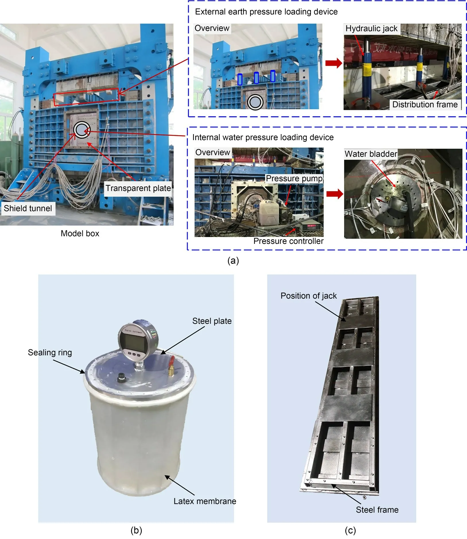
Fig.1 Loading system designed for the model test under internal water pressure conditions: (a) system composition;(b)water bladder;(c)distribution frame
The bearing capacity of a shield tunnel with a double-lining structure under internal water pressure has attracted considerable research attention and rese?archers have suggested that the interface between the outer segmental lining and the inner lining is a key factor influencing its bearing capacity(Su and Blood‐worth,2016;Liu et al.,2019).Before the inner lining is cast in-situ,the inner surface of the segmental lining can be treated with by a different construction method,such as chiseling,spreading waterproofing membrane,or embedding steel bars.Consequently,the ability of the lining–lining interface to transform shear and nor‐mal forces varies and exerts an influence on the bearing capacity of the double-lining.Some researchers have proposed lining–lining interface models to describe the mechanical property of the lining–lining interface.The lining–lining interface construction method influ‐ences the smoothness of the interface.International Tunnelling Association (ITA) (Working Group No.2,International Tunnelling Association,2000) suggested that only the normal force can be transmitted through the lining–lining interface when the interface is smooth.When the interface is uneven or dowelled jointing,both normal and shear forces can be transmitted through it.Further,Zhang et al.(2001a,2001b) and Yan et al.(2015)proposed radial and tangential springs to simu‐late the ability of the lining interface to transmit nor‐mal and shear forces.Based on the lining–lining inter‐face model,the mechanical behavior of the doublelining structure has been investigated (Song et al.,2018;Chen et al.,2020;Zhang XD et al.,2021).Wang et al.(2019a,2019b) conducted the model tests for double-lining possessing different interface types.The results indicated that when the lining–lining interface can transmit both the normal and shear forces,the maximum displacement of double-lining is smaller and failure occurs later.Yang et al.(2018)simulated the lining–lining interface using springs in their 3D finite element models.The results suggested that,as the compression stiffness of normal springs decreased,less internal water pressure was transmitted to the segmen‐tal lining.
The research described above has paid most atten‐tion to the effect of the lining–lining interface proper‐ty on the bearing capacity of double-lining and,so far,the effect of surrounding soil has been conventionally regarded as an external load.The stress distribution of soil under internal water pressure has been studied for that high minimum principal stresses of soil would lead to the hydraulic fracture of soil and to local water losses(Schleiss,1997;Simanjuntak et al.,2014;Zhou et al.,2015).In fact,the soil also provides resistance to constrain tunnel deformation under internal water pressure,but this effect of soil on bearing internal water pressure has been ignored.
In this study,considering the soil–double-lining interaction,the bearing capacity of the double-lining structure under internal water pressure is investigated through model tests and an analytical solution.First,double-lining model tests under sandy soil and highly weathered argillaceous siltstone conditions are con‐ducted.A double-lining model is specifically designed to simulate its performance under internal water pres‐sure.By comparing the behavior of the double-lining model under different soil conditions,the contribution of soil to the bearing capacity of the double-lining is analyzed.Subsequently,an analytical solution for the soil–double-lining interaction under internal water pres‐sure is proposed and verified against the model test results.The bearing contribution of soil to the internal water pressure is found to be closely related to the elastic modulus of the soil.
2 Design of the model test
2.1 Loading system and loading process
Figs.1 and 2 present the loading system designed for the model test.The loading system consisted of a model box with external earth pressure and internal water pressure loading devices.The model box was 1.8 m high,2.0 m wide,and 0.4 m thick internally.Two transparent Perspex plates with square shapes and a dimension of 0.8 m×0.8 m were placed in the middle of the model box to enable convenient observation dur‐ing the loading process.A circular opening was made in the middle of the transparent Perspex plate to facili‐tate the entry of water bladder into the tunnel.
Three hydraulic jacks were set above the soil to simulate the external earth pressure acting on the shield tunnel buried 50 m deep.A distribution frame with a high bending stiffness was designed to transform the point load into a distribution load.The internal water pressure loading device included a water bladder,water pressure pump,and automatic pressure controller.The water bladder was composed of an elastic latex mem‐brane,steel cover plates,and steel sealing rings.After the water bladder was filled with water,the internal water pressure was transmitted to the inner surface of the tunnel lining through the latex membrane.The water bladder was 420 mm in length,longer than that of the tunnel,to ensure that the water pressure was uniform along the tunnel.
The loading process involved two steps.First,external earth pressure was loaded through the hydrau‐lic jacks.The buried depth of tunnel crown was 50 m and the corresponding earth pressure was 900 kPa.In order to study the mechanical behavior of doublelining under different loads,the external earth pres‐sure was loaded to 360,720,and 900 kPa step by step.Each earth pressure step was kept stable for 30 min until the movement of soil stopped.The internal water pressure was increased by 0.01 MPa until the failure of the double-lining structure.Each water pressure step was kept for 5 min until the soil deformation reached stability.
2.2 Similarity relation
It has been established that a physical quantity is required to follow the similarity relation between a pro‐totype and a model.In this model test,the similarity ratios of geometryCLand unit weightCγwere selected as the basic similarity ratios.CLwas determined to be 1:20 by considering the boundary effect of the model box and the size of the tunnel model.In the 1gexper‐imental condition(gdenotes the acceleration of grav‐ity),the similarity ratio of unit weightCγwas deter‐mined to be 1:1.The similarity ratios for other quanti‐ties were similarly determined,and the values obtained are presented in Table 1.
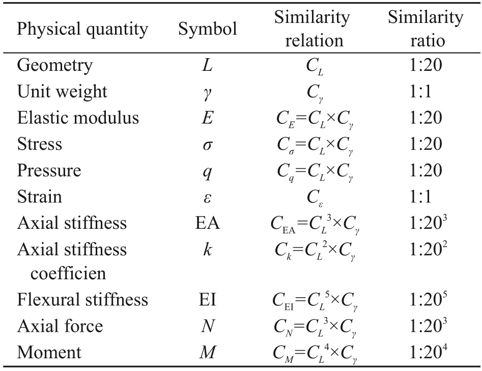
Table 1 Similarity ratios in this model test
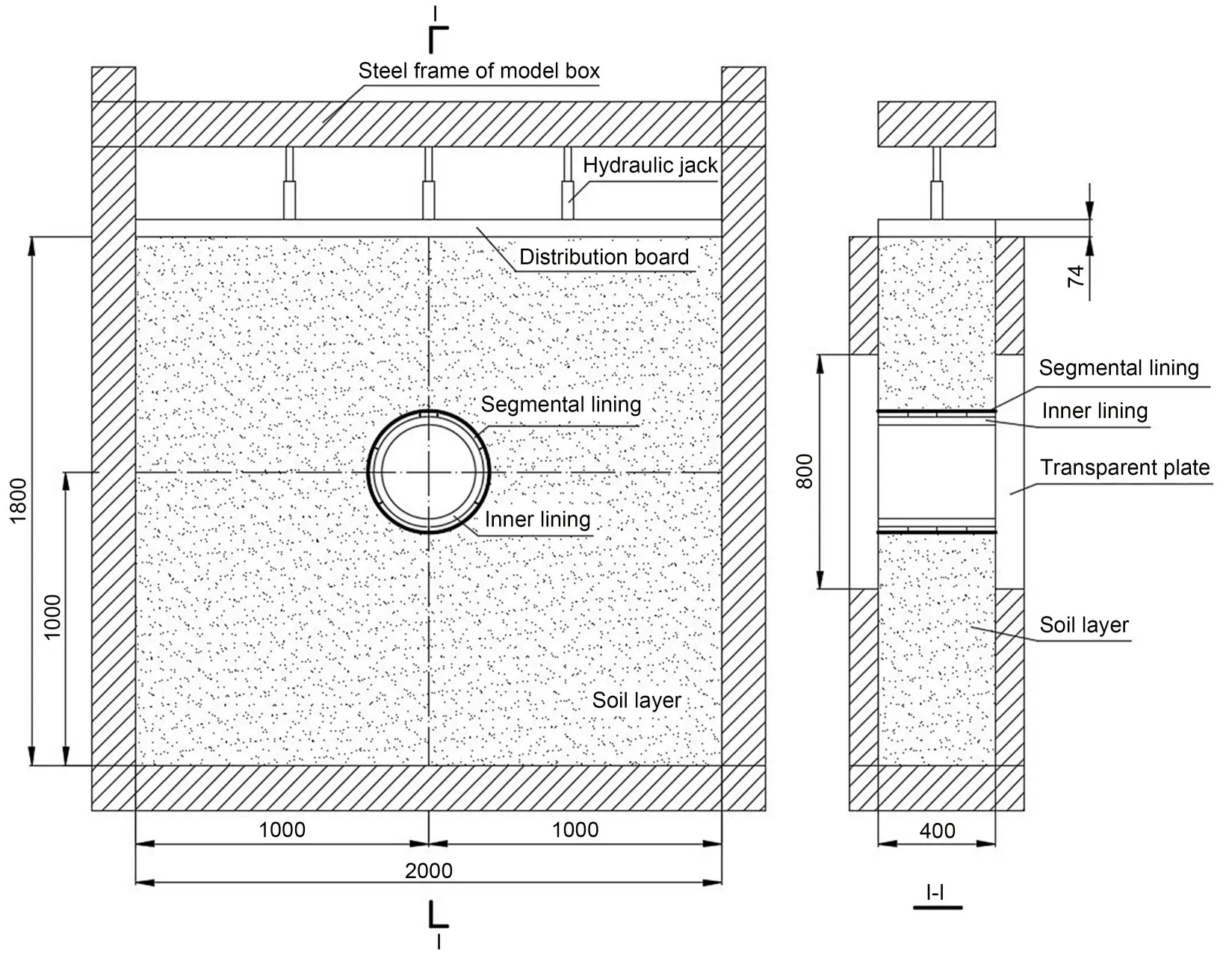
Fig.2 Schematic of the model box(unit:mm)
2.3 Modelling of double-lining
Fig.3 presents a cross-sectional view of the pro‐totype shield tunnel.As can be observed,the doublelining structure is composed of a segmental lining,an inner lining,and a waterproof membrane.The seg‐mental lining consists of one key block(F),two adja‐cent blocks (L1 and L2),and four standard blocks(B1–B4).The external radius of the segmental lining is 4.15 m,and the inner radius is 3.75 m.The con‐crete type used is C55,and the width of the segment is 1.60 m.The inner lining is cast in place using C50 grade concrete.The inner diameter of the inner lining is 6.4 m.A 1.2 mm-thick waterproof membrane is spread between the segmental and inner linings to enhance the waterproofing ability of the tunnel.

Fig.3 Prototype of the shield tunnel with a double-lining structure(unit:mm)
Fig.4 presents the 3D and cross-sectional views of the double-lining model.The model test was desig?ned to investigate the behavior of double-lining in the cross-section.The earth pressure,internal water pres‐sure,and the soil were kept identical along the longi‐tudinal direction.For the double-lining structure,the segmental lining was a staggered assembly with a 38°rotational shift to the adjacent rings.Therefore,four rings of tunnel of 0.4-m length are two cycles of the staggered installation of the segmental lining and can represent the double-lining structure.To simulate the mechanical response of the double-lining structure under internal water pressure,the lining material,joint configuration,and lining interface were specifically designed.
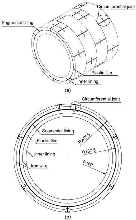
Fig.4 Schematic of the double-lining model: (a) 3D view;(b)cross-sectional view(unit:mm)
2.3.1 Similar materials for the linings
The concrete of the segmental and inner linings was simulated using gypsum mortar.Gypsum mortar is a mixture of gypsum,water,and diatomite.It is necessary for the concrete and gypsum mortar to sat‐isfy the similarity ratios of elastic modulus and com‐pressive strength.Therefore,uniaxial compressive strength tests were conducted on gypsum mortar spec‐imens containing different gypsum contents.The test results are presented in Fig.5.Based on the similarity ratio,a gypsum mortar mixed with water,gypsum,and diatomite in a ratio of 1.0:1.4:0.1 was adopted for the segmental lining and one with a ratio of 1.00:1.35:0.10 was adopted for the inner lining.The mechanical para?meters of the segmental and inner linings are presented in Table 2.
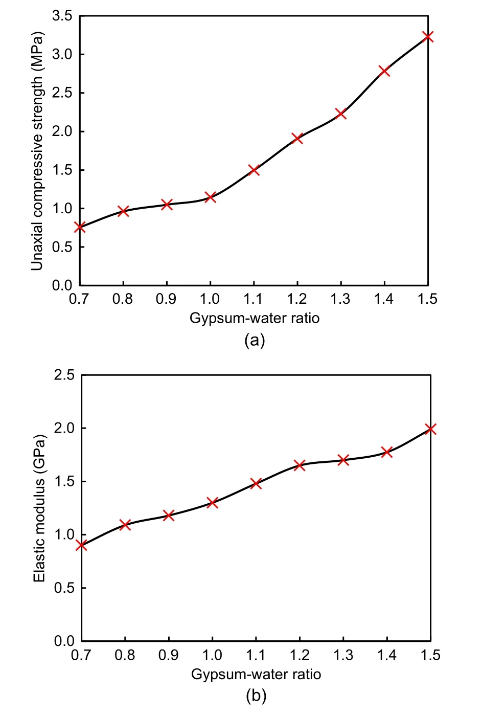
Fig.5 Test results for the gypsum mortar: (a) uniaxial compressive strength;(b)elastic modulus
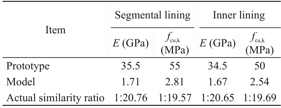
Table 2 Mechanical properties of the double-lining
Iron wire was used to simulate the rebar in the segmental and inner linings.In the presence of inter‐nal water pressure,the lining is expected to crack under the action of the tensile force produced in the lining.After the lining cracks,the rebar primarily bears the tension.Therefore,the arrangement of the iron wire was that the similarity ratio of axial stiffnessCEA(1:203) was obeyed.The elastic modulus of the iron wire and rebar is 200 GPa.The reinforcement ratio of the segment in the prototype is 0.9%.Therefore,two iron wires with diameters of 0.8 mm were arranged in each segmental lining.The reinforcement ratio of the inner lining in the prototype was 2.3%.Accordingly,16 rings of iron wires with diameters of 1.0 mm were set in the inner lining of the model.
2.3.2 Modelling of the segmental joint
Simulating a segmental circumferential joint is one of the primary challenges faced during the execu‐tion of the model test.Wang et al.(2019a,2019b)and Guo R et al.(2019) proposed the creation of grooves at the joint position in the gypsum mortar ring.This method could effectively simulate the bending stiff‐ness of the joint.However,it is not reasonable to sim‐ulate the tension capacity of the joint accurately.Under the effect of internal water pressure,the joint is under tension and bears the existing load through bolts.In this condition,the gypsum mortar ring with grooves cracks and cannot withstand the tension.To overcome this shortcoming,a novel approach for modelling the segmental joints was proposed.As shown in Fig.6,the joint model was composed of two iron pieces,two iron rods,two screws,and an iron wire.To simulate the mechanical behaviour of a real joint,the bending stiffness and tension stiffness of the joint should satisfy a similar relation between the model and prototype.The iron rods were set at the hole of the iron plates to simulate the bending stiffness of the joint.The geo‐metric size of the iron rod was determined through a similar relation of bending stiffness,and the bending stiffness of the joint was obtained by numerical simu‐lation.The diameter and length of the iron rod were 1.6 and 25.0 mm,respectively.The iron wire was set to simulate the tension capacity of the joint,fixed at the external surface of segment by a screw.The iron wire of the model and the bolt of the prototype should satisfy a similar relation of tension stiffness coefficient,as shown in Eq.(1).
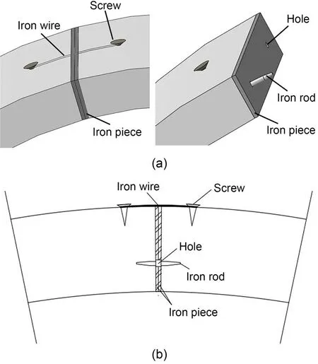
Fig.6 Detailed illustration of the circumferential joint:(a)3D view;(b)cross-sectional view
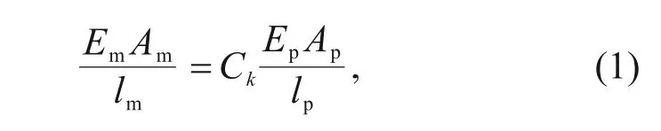
whereE,A,andlrefer to the elastic modulus,area,and length,and subscripts m and p refer to the iron wire and bolt,respectively.A=πD2/4,andDrefers to the diameter.Ckrefers to the similarity ratio of the ten‐sion stiffness coefficient and is equal to 1:202.In this study,Ep=Em=200 GPa,Dp=36 mm,andlp=435 mm.Thus,the iron wire was adopted asDm=0.6 mm andlm=30 mm.
2.3.3 Modelling of the lining–lining interface
According to ITA(Working Group No.2,Inter‐national Tunnelling Association,2000),the doublelining structure can be divided into a double-shell structure and the composite structure based on the lining–lining interface smoothness.For the doubleshell structure,the interface is relatively smooth,and only the normal force can be transmitted through the interface.For the composite structure,the interface undergoes chiselling,grooving,or embedding rebars.Both the normal and shear forces can be transmitted through the interface.For the shield tunnel subjected to internal water pressure,laying a waterproof mem‐brane between the inner and segmental linings is gen‐erally essential.The surface of the waterproof layer then becomes smooth,and the tunnel can be con‐sidered as a double-shell structure.Therefore,in the model test,a smooth plastic film was set inside the seg‐mental lining to simulate the interface with a water‐proof layer,as shown in Fig.7.
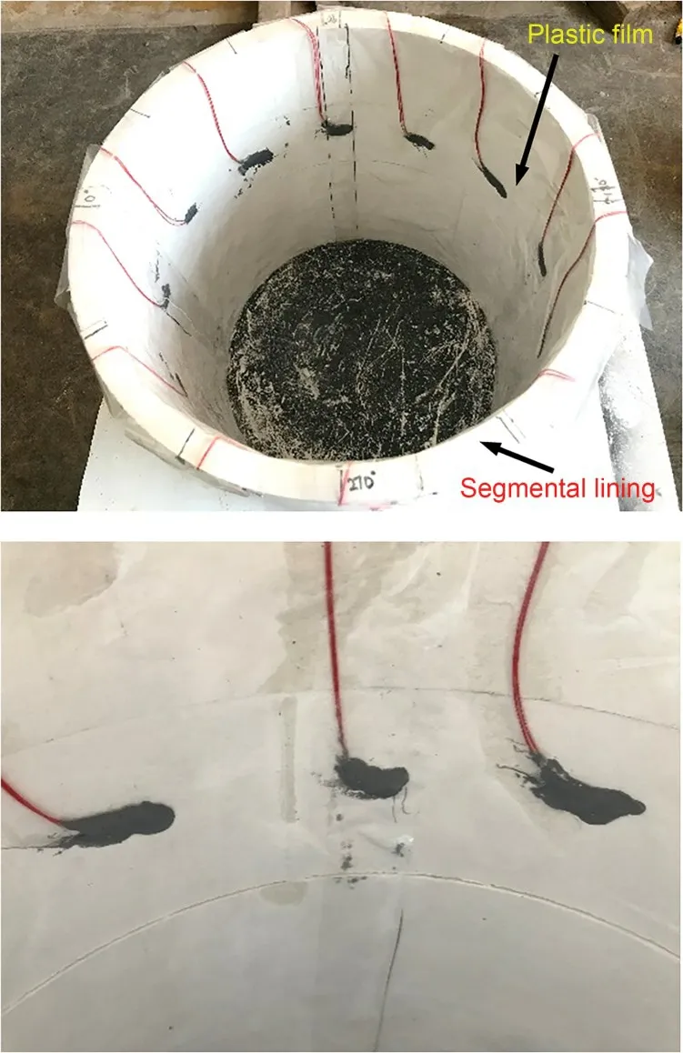
Fig.7 Modelling of the lining–lining interface
2.4 Modelling of soil
Under the effect of internal water pressure,the shield tunnel deforms outwards,and soil provides the necessary resistance to constrain the resulting tunnel deformation.The tunnel lining and the surrounding soil collectively bear the internal water pressure.The soil resistance is closely related to the elastic modulus of the soil.The elastic modulus must satisfy the similar‐ity ratio.To investigate the influence of the soil condi‐tion on the bearing capacity of the double-lining struc‐ture,two types of soils were prepared: sandy soil and highly weathered argillaceous siltstone.Sandy soil was simulated using a material composed of barite powder,plastic foam,glass sand,and glycerol.Plastic foam,glass sand,and glycerol were mixed in a volume ratio of 1.0:1.0:0.5.Following this,barite powder was combined with the mixture in a mass ratio of 1:1.The highly weathered argillaceous siltstone condition was simulated using river sand.Through geotechni‐cal tests,the elastic modulus of sandy soil and highly weathered argillaceous siltstone were determined to be 2.5 and 50.0 MPa,respectively,which corresponded to the respective values of 50 MPa and 1 GPa in the prototype.
2.5 Layout of measurement
To evaluate the mechanical behaviour of doublelining tunnels under the effect of internal water pres‐sure,the lining internal force and earth pressure acting around the tunnel were measured,as shown in Fig.8.For this,strain gauges were arranged at 12 different sections around the circumference and are denoted as S1–S12.The strain gauges were installed on the outer and inner surfaces of the double-lining and lining–lining interface at every section.These strain gauges were used to calculate the internal force acting on the segmental and inner linings.Additionally,earth pres‐sure cells were installed at 45° intervals on the soil–lining interface and are denoted as P1–P8.
3 Test results and analysis
In this section,the internal force and earth pres‐sure under different soil conditions were compared to investigate the effect of soil on the bearing capacity of the double-lining structure.Also,the failure mode of the double-lining structure under high internal water pressure was analysed.The bending moment and axial force can be obtained using Eq.(2).
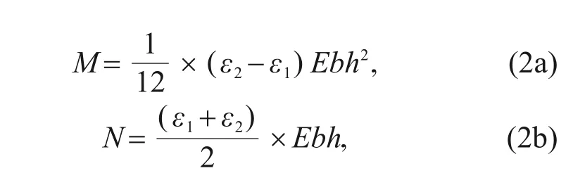
whereMandNare the bending moment and axial force,respectively;ε1andε2are the strains at the exter‐nal and inner surfaces of the segmental and inner lin‐ings,respectively;bandhare the width and thickness of the segmental and inner linings,respectively.
3.1 Internal force
3.1.1 Bending moment
Fig.9 illustrates the variation of bending moment with the internal water pressure under the sandy soil and highly weathered argillaceous siltstone conditions.As can be observed,the variation of bending moment due to a change in the internal water pressure was min‐imal under both the sandy soil and highly weathered argillaceous siltstone conditions.For the segmental lining,the variation of bending moment was mostly less than 50 kN·m,except at the invert under sandy soil conditions.For the inner lining,the largest varia‐tion can be observed at the invert under highly weath‐ered argillaceous siltstone conditions,which exceeded 100 kN·m.The variation of bending moment at other positions was within 100 kN·m.Thus,it can be con‐cluded that the bending moment changes slightly dur‐ing internal water pressure loading regardless of the soil condition.
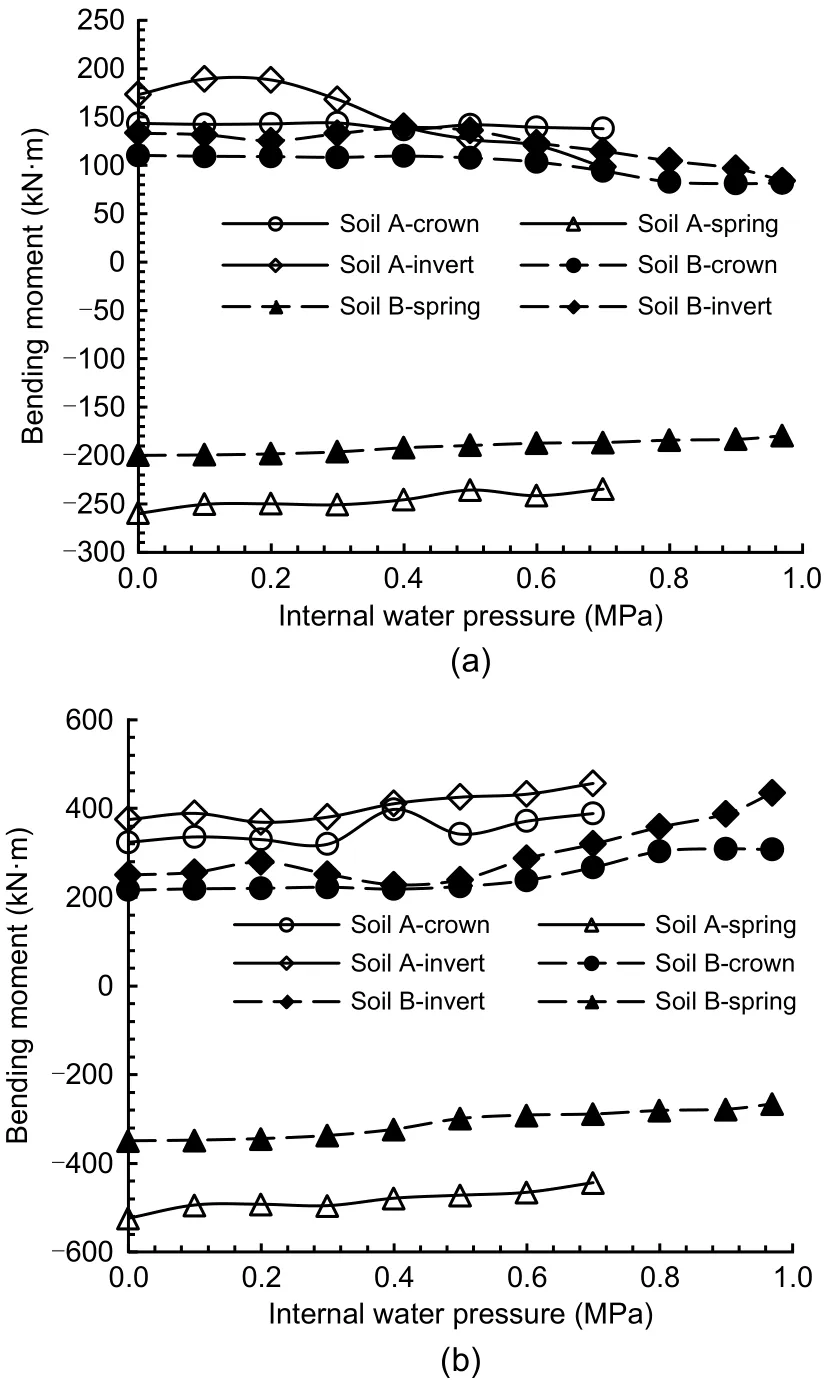
Fig.9 Bending moment under different soil conditions:(a) segmental lining;(b) inner lining.Soil A: sandy soil;Soil B:highly weathered argillaceous siltstone
3.1.2 Axial force
Fig.10 illustrates the variation of axial force with the internal water pressure under sandy soil and highly weathered argillaceous siltstone conditions.It can be observed that the variation trend followed by the axial force under the sandy soil and highly weathered argillaceous siltstone conditions was similar.When the earth pressure loading was completed and internal pressure was not applied,the axial force acting on the lining was compressed.With an increase in the inter‐nal water pressure,the axial force acting on the seg‐mental and inner linings decreased and developed into tension.The tensile strength of concrete is signifi‐cantly lower than its compressive strength.Thus,ten‐sile cracks may appear at the double-lining structure.The magnitude of compression at the crown and invert was relatively small compared with that at the spring before the loading of internal water pressure.There‐fore,the lining at the crown and invert is more prone to crack formation under the effect of internal water pressure.
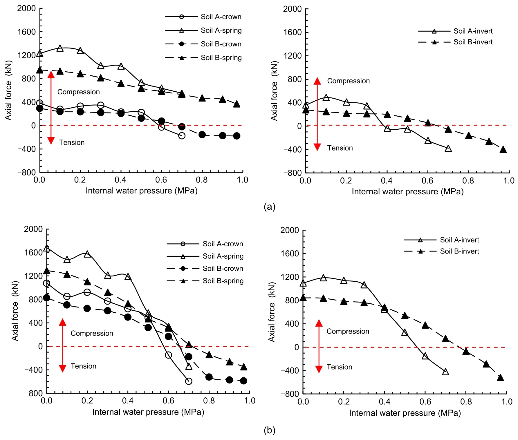
Fig.10 Axial forces under different soil conditions:(a)segmental lining;(b)inner lining
However,the variation rate of axial force under the sandy soil condition was found to be larger than that under the highly weathered argillaceous siltstone condition.Considering the segmental lining as an example,the axial force acting at the crown under the sandy soil condition changed from 381.4 to ?176.5 kN with an increase in the internal water pressure.The decrement of the axial force was 557.9 kN under the sandy soil condition,which was 18% larger than that observed under the highly weathered argillaceous silt‐stone condition.As the elastic modulus of soil decre?ases,the surrounding soil provides less resistance and,consequently,more internal water pressure is borne by the double-lining.In general,under internal water pressure,the axial force acting on the double-lining decreased significantly,whereas the bending moment changed only slightly.The double-lining deforms out‐wards under the internal water pressure.The radial dis‐placement of double-lining is nearly the same along the circumferential direction.Thus,the double-lining is under tension and no bending deflection occurrs.The axial force changes significantly while the bending moment changes slightly.The variation rate of the axial force can reflect the sharing ratio of internal water pressure for the double-lining under different soil conditions.The variation rate of axial force for the double-lining structurekNis defined in Eq.(3),and it was 3218 kN/MPa under the sandy soil condition,and 2111 kN/MPa under the highly weathered argilla‐ceous siltstone condition,which indicated that the sharing ratio of internal water pressure for the doublelining decreased by 35.40%.
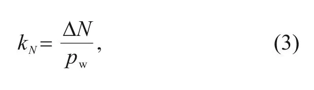
where ΔNis the variation of axial force acting on the double-lining,andpwis the internal water pressure.
By comparing the variation of axial force between the segmental lining and inner lining,it can be con‐cluded that the axial force decrement for the inner lin‐ing is significantly more than that for the segmental lining.Under the highly weathered argillaceous silt‐stone condition,the axial force decrement for the seg‐mental lining at the crown was 473 kN and that for the inner lining was 1418 kN.The axial force decre‐ment for the inner lining was 3.0,2.8,and 2.1 times more than that for the segmental lining at the crown,spring,and invert,respectively.The axial force decre‐ment is used to measure the sharing ratio of internal water pressure between the segmental and inner lin‐ings,as shown in Eq.(4).The sharing ratio between the segmental and inner linings was 1.0:2.7 and 1.0:2.6 under the sandy soil and highly weathered argillaceous siltstone conditions,respectively.The sharing ratio between the segmental and inner linings is not rele‐vant to the soil condition;however,it is relevant to the lining stiffness.The segmental lining demonstrates low axial stiffness owing to the existence of joints.The inner lining plays an important role in internal water pressure bearing.Thus,the inner lining is more prone to damage under the effect of internal water pressure.
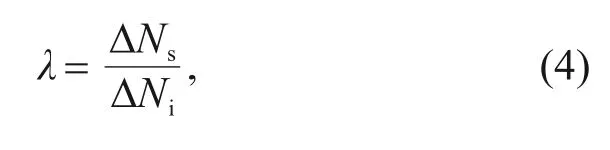
whereλrefers to the sharing ratio of internal water pressure between the segmental and inner linings,and ΔNsand ΔNirefer to the axial force decrement observed for the segmental and inner linings,respectively.
3.2 Earth pressure
3.2.1 Variation in earth pressure under the highly weathered argillaceous siltstone condition
The variation of earth pressure under the highly weathered argillaceous siltstone condition was anal‐ysed.Fig.11 presents the development of earth pres‐sure during external soil loading.It can be observed that the earth pressure increased as the external soil load was imposed.The overburden increased to 20,40,and 50 m in three steps.The corresponding earth pressure increments at the crown are denoted as Δ1,Δ2,Δ3,respectively.The quantitative relationship can be presented as Δ1≈Δ2≈2Δ3≈340 kPa.After the com‐pletion of loading,the earth pressure reached 815 kPa at the crown and 883 kPa at the invert.The earth press?ures at the left and right springs were 377 and 469 kPa,respectively.The lateral earth pressure coefficient was 0.45 in the model test.
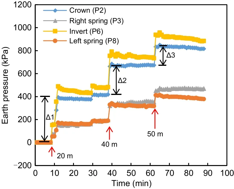
Fig.11 Variation of earth pressure with external soil load
Fig.12 presents the variation of earth pressure with the increase of internal water pressure.From the figure,it can be observed that the double-lining struc‐ture has undergone the following three stages under the effect of internal water pressure.First,when the internal water pressure was less than 0.4 MPa,the double-lining structure was in the elastic stage.The earth pressure increased almost linearly with the inter‐nal water pressure.Second,when the internal water pressure reached 0.4 MPa,the double-lining cracked and subsequently entered the damage stage.The earth pressure still followed a linear trend;however,the rate of increase of earth pressure in the damage state was visibly larger than that observed in the elastic state.Finally,when the internal water pressure incre?ased to 0.97 MPa,the double-lining structure entered a failure stage.At this stage,the joint opening increased sharply and the joint eventually fractured.The seg‐mental lining deformed outward continuously at a con‐stant internal water pressure and,consequently,the double-lining structure lost its bearing capacity.
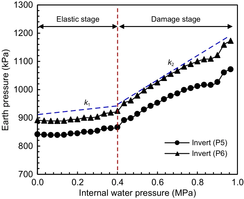
Fig.12 Variation of earth pressure with internal water pressure
To compare the soil resistance when the doublelining is in the elastic and damage states,the variation rate of earth pressure with internal water pressure,ki,is defined as shown in Eq.(5),and the results are pre‐sented in Table 3.The variation rate of earth pressure in the damage stage was approximately 3.0 times of that in the elastic stage at the crown and invert,and it was 2.0 times of that in the elastic stage at the left and right springs.When the double-lining cracks,the axial ten‐sile stiffness of the double-lining is reduced.Therefore,the surrounding soil has to bear more internal water pressure.Moreover,the axial forces at the crown and invert are less than those at the spring.Thus,the tensiledamages at the crown and invert are more severe.Consequently,the variation rate of earth pressure incr?eases more significantly at the crown and invert.
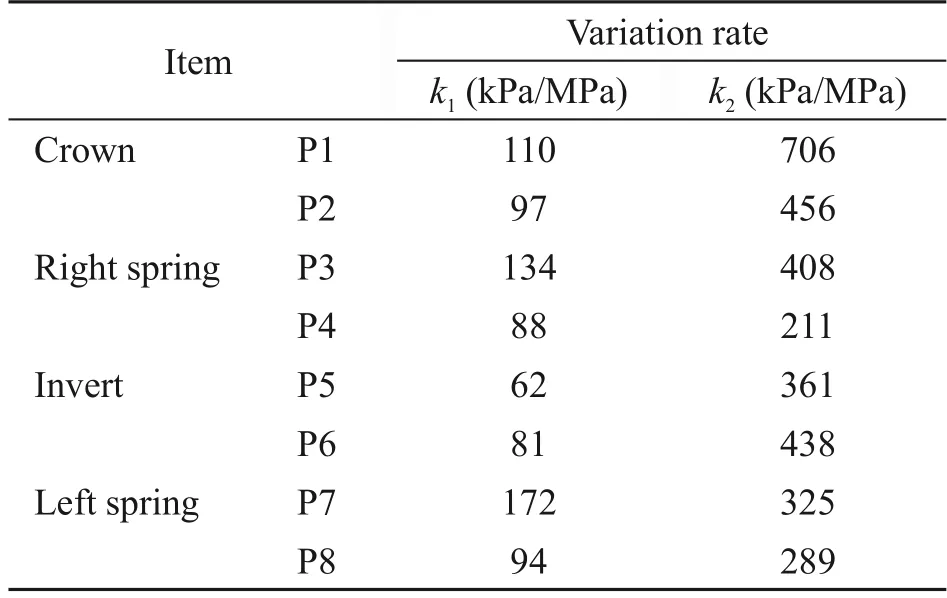
Table 3 Variation rate of earth pressure with internal water pressure
wherei=1,2 refers to the elastic and damage stages,respectively;ΔSiand Δpwirefer to the increments in earth pressure and internal water pressure during the corresponding stage represented byi.
3.2.2 Comparison of earth pressure under different soil conditions
Fig.13 illustrates the variation in earth pressure under the sandy soil and highly weathered argillaceous siltstone conditions.During the loading process of internal water pressure,the double-lining under the sandy soil condition experienced the following three stages: elastic stage,damage stage,and failure stage.When the internal water pressure reached a crack‐ing point of 0.33 MPa,the double-lining was in the damage stage,and the variation rate of earth pressure increased.When the internal water pressure reached 0.70 MPa,the joint opening increased sharply and the double-lining failed.However,the increment in the earth pressure under the sandy soil condition was obvi‐ously less than that under the highly weathered argilla‐ceous siltstone condition.This result indicates that the soil resistance effect demonstrated in the highly weath‐ered argillaceous siltstone condition is significantly higher than that demonstrated in the sandy soil condi‐tion,which improves the overall internal pressure bear‐ing capacity of the soil-lining structure.
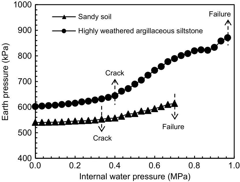
Fig.13 Earth pressure under different soil conditions
To investigate the contribution of soil and its influence on the bearing capacity of the double-lining,the contribution of soil to the internal water pressure is defined as the ratio of the increment in the earth pressure to the internal water pressure,as shown in Eq.(6).Fig.14 presents the change in the contribution of soil to the internal water pressure.It can be observed that the contribution of soil to the internal water pres‐sure increased slowly during the elastic stage,where‐as it increased rapidly during the damage stage.Dur‐ing the elastic stage,the highly weathered argillaceous siltstone condition contributed 10.4% of the internal water pressure,while the contribution of the sandy soil was only 3.7%.Compared with sandy soil,the contribution of highly weathered argillaceous siltstone was enhanced by only a small margin.Therefore,the cracking point of the double-lining rose slightly from 0.33 to 0.40 MPa.During the damage stage,the con‐tribution to the bearing capacity reached 27.8% for highly weathered argillaceous siltstone and 10.5% for sandy soil.Thus,the contribution of the highly weath‐ered argillaceous siltstone condition was substantially higher than that of the sandy soil condition.Conse‐quently,the ultimate bearing capacity of the doublelining structure increased from 0.70 to 0.97 MPa with a large amplitude when the soil type changed from sandy soil to highly weathered argillaceous siltstone.Thus,the contribution of soil to the internal water pressure increased when the elastic modulus of soil improved,which is beneficial to the joint bearing capacity of the soil-lining.
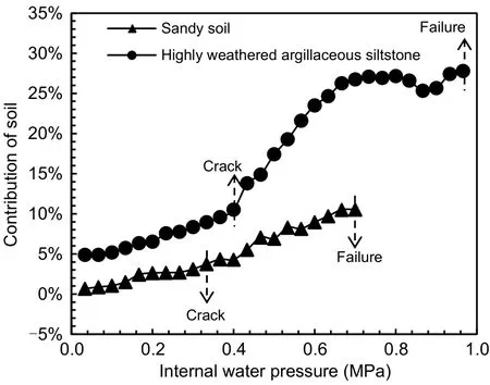
Fig.14 Contribution of soil under different soil conditions
whereηrefers to the contribution of soil to the inter‐nal water pressure,and ΔSrepresents the increment in earth pressure during internal water pressure loading.
3.3 Failure mode
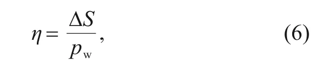
As the internal water pressure increased,tensile cracks continued to appear in the double-lining.The failure characteristics of the double-lining structure were similar under both the sandy soil and highly weathered argillaceous siltstone conditions.The doublelining model after failure under the highly weathered argillaceous siltstone condition is analysed.Fig.15 shows the crack distribution in the double-lining struc‐ture for the final failure state.As can be observed,for the segmental lining,cracks appeared at the crown,spring,and invert.Multiple longitudinal cracks occur?red at the crown and invert,whereas the number of cracks at the left and right springs was relatively small.For the inner lining,the crack distribution was similar to that of the segmental lining.Cracks were primarily concentrated at the areas of the crown and invert.Dur‐ing the loading of internal water pressure,cracks first appeared at the crown,then at the invert,and finally at the left and right springs.Figs.16 and 17 present the corresponding images for the segmental and inner lin‐ings after failure,respectively.The crack widths at the crown,right spring,invert,and left spring are denoted asD1,D2,D3,andD4,respectively.For the segmental and inner linings,the crack width relationship can be expressed asD1≈D3>D4>D2.Thus,it can be concluded that the damage at the crown and invert was more severe.The development of cracks was closely related to the internal force acting on the tunnel,which has been introduced in Section 3.1.The axial force at the crown and invert changed to tension earlier than that at the spring.Consequently,cracks first occurred at the crown and invert.As the internal water pressure increased,the crack number and width at the crown and invert correspondingly increased,and the result‐ing damage was more severe.
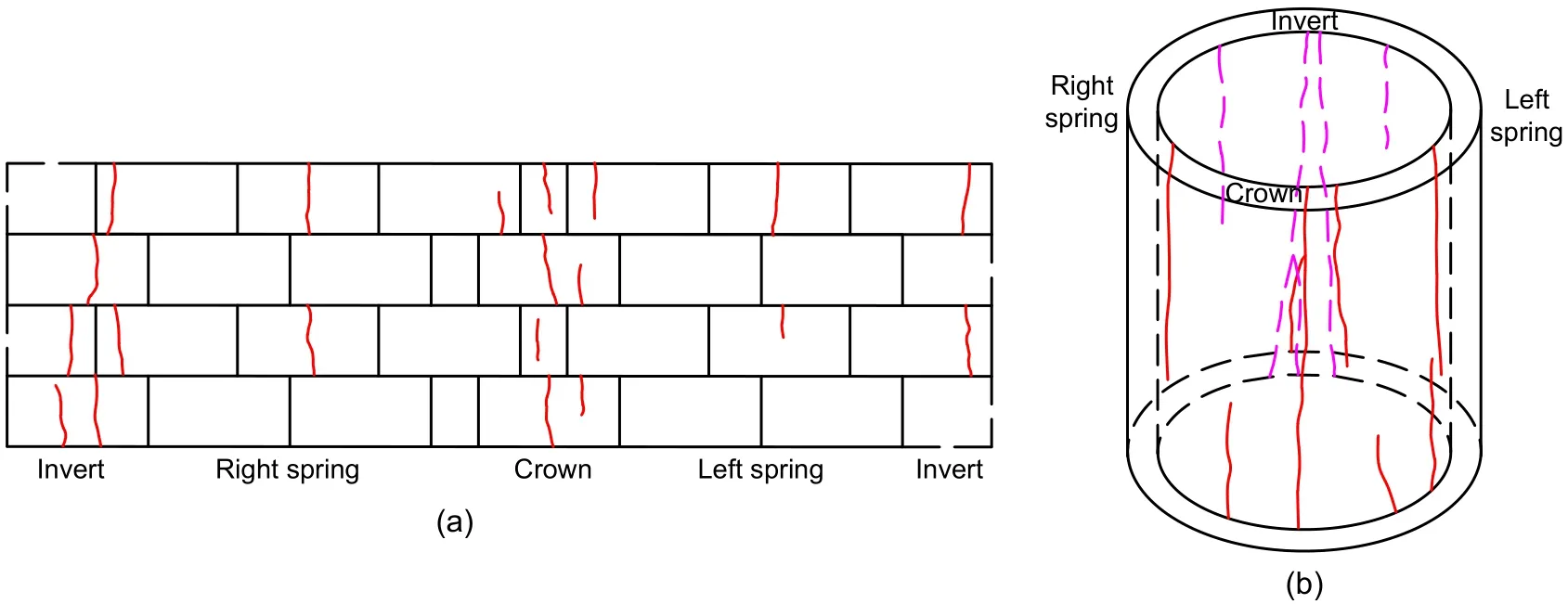
Fig.15 Crack distribution in the double-lining structure:(a)segmental lining;(b)inner lining
From Figs.16 and 17,it can be observed that the crack width at the inner lining was larger compared with that at the segmental lining.Additionally,the cracks on the inner lining were mostly longitudinal cracks.This can be attributed to the fact that the inner lining bears a higher proportion of the internal water pressure,which causes severe damage to the inner lin‐ing structure.
The double-lining structure failed in the final stage owing to the occurrence of a joint fracture.As can be observed from Fig.16,the joint fractured and was incapable of withstanding any more tension.More‐over,the cracks in the segmental lining mostly app?eared near the joint of the adjacent ring.It can be seen that the cracks in the inner lining usually occurred near a segmental joint.This phenomenon indicates that the segmental joint possesses lower axial stiffness and ten‐sile strength.Thus,the segmental joint can be thought of as a weak-point in the double-lining structure.
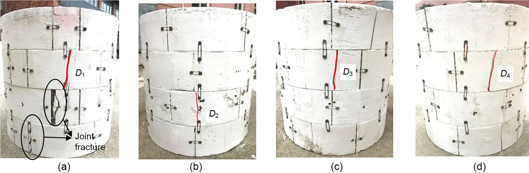
Fig.16 Object image of the segmental lining after failure:(a)crown;(b)right spring;(c)invert;(d)left spring
In summary,we can conclude that cracks are mostly distributed at the crown and invert near a seg‐mental joint,and more severe damage appears on the inner lining.Thus,the crack width at the crown and invert of the inner lining and close to the segmental joint must be emphasized during the design phase.
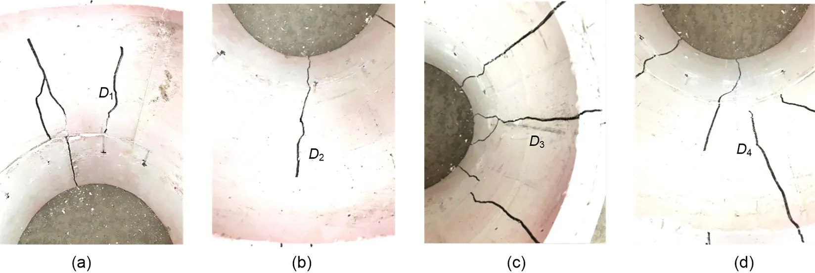
Fig.17 Object image of the inner lining after failure:(a)crown;(b)right spring;(c)invert;(d)left spring
4 Analytical solution
The model test results indicate that the contribu‐tion of soil to the internal water pressure is crucial to the bearing capacity of the double-lining.The contri‐bution of soil is related to the elastic modulus of the soil.To show further the variation of the soil contribu‐tion to the internal water pressure with the elastic mod‐ulus of the soil,an analytical solution for the doublelining under the effect of internal water pressure is pro‐posed.For this,the segmental and inner linings are assumed to be thick-walled cylinders.The axial stiff‐ness of the segmental lining is affected owing to the existence of joints and the axial stiffness of the inner lining reduces after cracking,which is considered in the analytical solution.
4.1 Analytical model for the interaction between soil and double-lining
4.1.1 Mechanical model
Fig.18 depicts a mechanical model of the doublelining under the effect of internal water pressure.The double-lining is embedded in an infinite elastic layer of soil.As mentioned earlier,the segmental and inner linings are assumed to be thick-walled cylinders.The elastic modulus and Poisson’s ratio of the soil,seg‐mental lining,and inner lining are denoted asE0,E1,E2,v0,v1,andv2,respectively.Moreover,the outer and inner radius of the segmental lining are denoted asr0andr1,respectively,while the inner radius of the inner lining is denoted asr2.
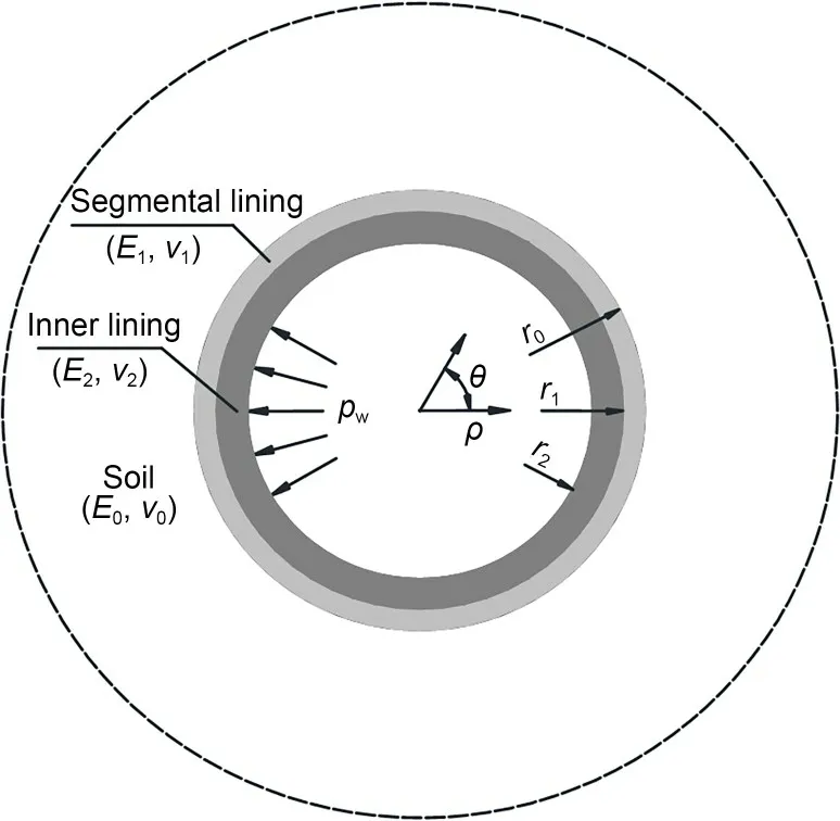
Fig.18 Mechanical model of the double-lining under internal water pressure.ρ is the radius;θ is the angle
4.1.2 Derivation of the analytical solution
It is known that the internal water pressurepwis borne by the segmental and inner linings and the soil layer.As shown in Fig.19,the pressures transmitted to the segmental lining and soil are assumed to beP1andP2,respectively.
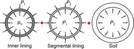
Fig.19 Load distribution for the tunnel and soil layer
The inner lining,segmental lining,and soil layer can be solved using the Lame solution.According to the Lame solution,the radial displacement function is given as
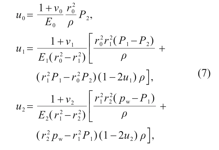
whereu0,u1,andu2refer to the radial displacement of the soil layer,segmental lining,and inner lining,respectively.
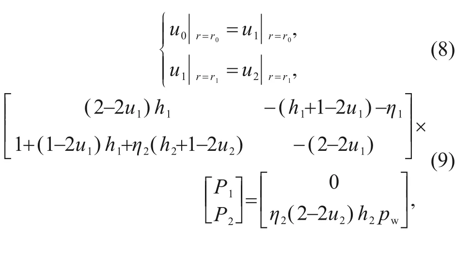
The radial displacements at the lining–lining interface and soil–lining interface satisfy displacement coordination,as shown in Eq.(8).Further,Eq.(8)can be transformed into a matrix form,and the interface pressure can be solved,as shown in Eq.(9).
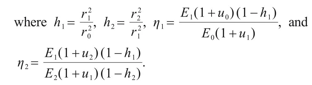
Then,the stress of segmental and inner linings can be solved according to the Lame solution.The maximum circumferential normal stress occurs at the inner surface of the inner lining,which can be used to determine the cracking load of the double-lining,as shown in Eq.(10).
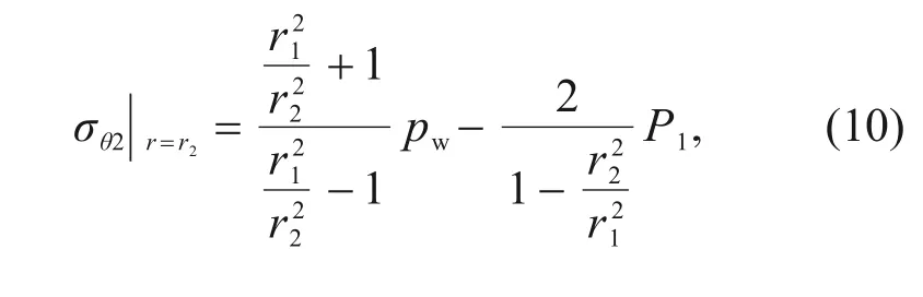
whereσθ2refers to the circumferential normal stress acting on the inner lining.
4.1.3 Elastic modulus of the segmental and inner linings
As mentioned earlier,the segmental lining is assumed to be a homogeneous thick-walled cylinder.However,the axial stiffness of the circumferential joint is different from that of the segment.Thus,an equiva‐lent elastic modulus was calculated to represent the axial stiffness of the entire segmental lining.As shown in Fig.20,the segmental lining can be regarded as a tandem system composed of segments and joints under tension.The circumferential displacement of the seg‐mental lining is equal to the sum of the circumferen‐tial displacement of the segment and that of the joint,as shown in Eq.(11).Therefore,the equivalent elastic modulus of the segmental lining can be derived as shown in Eq.(12).
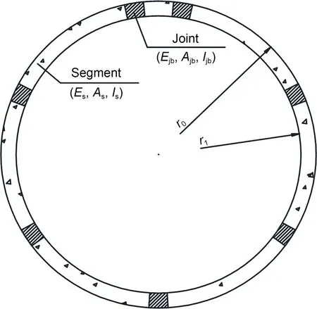
Fig.20 Schematic of the segmental lining
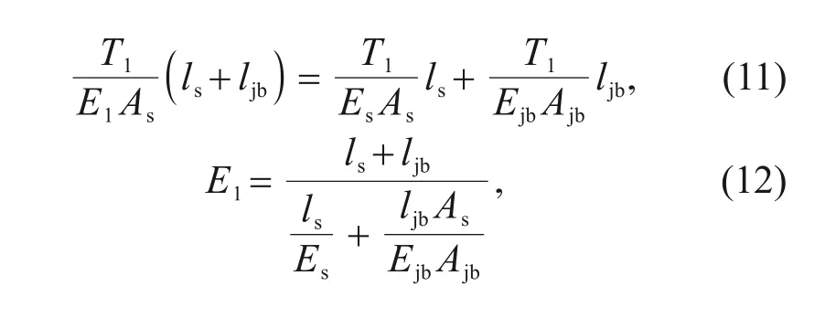
whereT1represents the tensile force acting on the seg‐mental lining;Es,As,andlsdenote the elastic modulus,area,and length of the segment,respectively;Ejb,Ajb,andljbrepresent the elastic modulus,area,and length of the joint bolt,respectively.
After the inner lining cracks,its axial stiffness red?uces.The Comité Euro-International du Beton (CEB)model was proposed to describe the mechanical behav‐iour of reinforced concrete subjected to tension in terms of an average strain (CEB,1985;Stramandinoli and La Rovere,2008).The average strain of reinforced concrete with cracks is shown in Eq.(13).Therefore,the axial stiffness of the inner lining after cracking can be derived by Eq.(14).
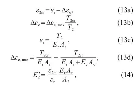
whereε2mrepresents the average strain on the inner lining;εrrepresents the strain in the rebar at a cracked section;Δεcrepresents the contribution of concrete between cracks due to its bond with the rebar;Δεc,maxrepresents the contribution of concrete at the begin‐ning of the cracking process;T2represents the tensile force acting on the inner lining;T2crrepresents the ten‐sile force of the inner lining when cracking;A2repre‐sents the area of the inner lining;ErandArdenote the elastic modulus and area of the rebar in the inner lin‐ing,respectively;EcandAcrepresent the elastic modu‐lus and area of concrete in the inner lining,respec‐tively;refers to the elastic modulus of inner lining after cracking.
4.2 Verification of the analytical solution
The analytical solution is verified with the model test conducted under the highly weathered argillaceous siltstone condition.The earth pressures obtained from the model test and analytical solution are compared,as shown in Fig.21.As can be observed,the earth pres‐sures obtained from the model test and analytical solu‐tion are similar,with an average deviation of 7.86%.The cracking point derived by the analytical solution lies at 0.35 MPa,which is close to the cracking point of 0.40 MPa obtained from the model test.
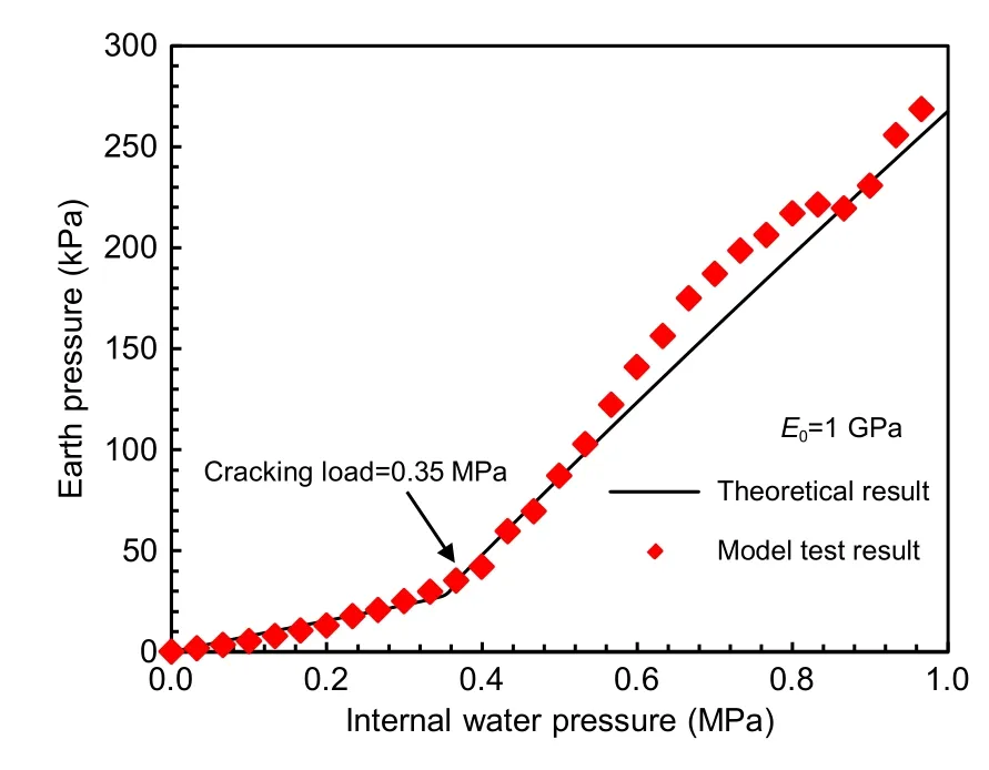
Fig.21 Comparison between model test and theoretical results
4.3 Effect of soil on the tunnel capacity
The variation in the contribution of soil to the internal water pressure with the internal water pressure is illustrated in Fig.22.When the double-lining is in the elastic stage,the soil contribution remains stable.After the inner lining cracks,the soil contribution rises and becomes steady with the increase in internal water pressure.For a tunnel lining subjected to internal water pressure,there exist two safety control standards to be followed during the design.First,the cracking point of the lining is selected as a safety control standard.Sec‐ond,the inner lining is allowed to crack,and the radial displacement of the double-lining is selected as a safety control standard to limit the crack width and joint opening.Therefore,both soil contributions,under the elastic and damage stages,are useful in the design of double-linings.
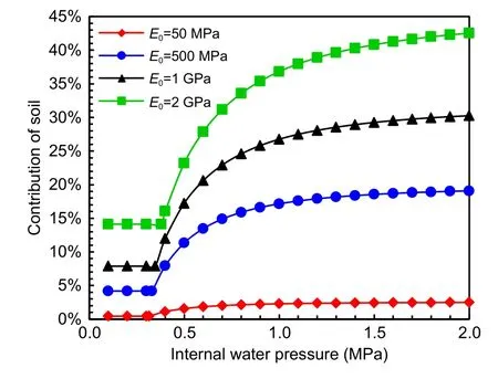
Fig.22 Variation of soil contribution with internal water pressure
The variation in the soil contribution to the inter‐nal water pressure with the elastic modulus of soil is presented in Fig.23.As the elastic modulus of the soil increases,the soil contribution rises;however,the rate of increase declines.When the elastic modulus of soil is 50 MPa,the soil contribution under the elastic stage is only 1%,and the soil has little effect on the bearing capacity of the double-lining.The soil contribution under the elastic stage reaches 19.2%when the elastic modulus of soil is 3 GPa.When the double-lining is designed based on the strength control standard,it is suggested that the soil contribution should be consid‐ered as the elastic modulus of soil with a value greater than 3 GPa.When the elastic modulus of soil is below 3 GPa,the soil contribution can be used as a reserve of structural safety.Soil contributes to 2.5%of the inter‐nal water pressure during the damage stage when the elastic modulus is 50 MPa.When the elastic modulus increases to 500 MPa,the soil contribution reaches 19.1%.When the double-lining is designed using the deformation control standard,the soil contribution must be calculated as the elastic modulus of soil with a value greater than 500 MPa.
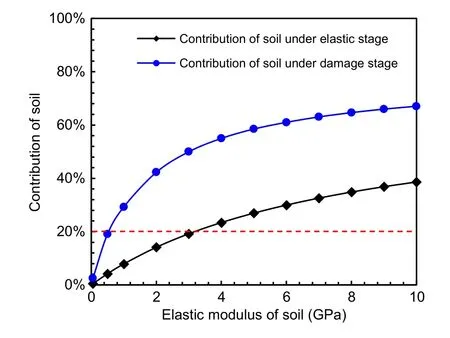
Fig.23 Variation of soil contribution with the elastic modulus of soil
4.4 Discussion of soil contribution
The results of model tests and analytical solution showed that the contribution of soil on the tunnel bear‐ing capacity increases with an increase of the soil elas‐tic modulus.Consequently,the internal water pressure controlled by double-lining decreases,and the doublelining design can be optimized.Since the inner lining plays a vital role on bearing internal water pressure,the thickness of the inner lining is selected as the opti‐mized design parameter.Under the designed internal water pressure,the thickness of inner lining can be optimized based on the strength or deformation safety control standard.
Fig.24a shows the thickness of inner lining given the variation of the soil contribution based on the str?ength safety control standard.It can be observed that the thickness of the inner lining decreases linearly as the soil contribution increases.Taking the internal water pressures of 0.3,0.4,and 0.5 MPa as the exam‐ple,when the soil contribution increases from 0 to 50%,the thickness of the inner lining decreases from 0.53 to 0.22 m,from 0.69 to 0.29 m,and from 0.86 to 0.36 m,respectively.The thickness of the inner lining is decreased by about 59%.Furthermore,the reduc‐tion in the thickness of the inner lining is independent of the internal water pressure.The soil contribution can decrease the thickness of the inner lining very signifi‐cantly.In addition,when the soil contribution increases to approximately 90%,the thickness of the inner lin‐ing can be reduced to zero,which means the segmen‐tal lining is enough to bear internal water pressure and there is no need for an inner lining.Fig.24b shows the variation of thickness of the inner lining with soil contribution based on the deformation control stan‐dard.In this case,the inner lining is allowed to crack,and a joint opening of 2 mm is selected as the defor‐mation control standard.The thickness of the inner lining decreases linearly with soil contribution as well.When the soil contribution increases to 80%,the inner lining is no longer necessary.
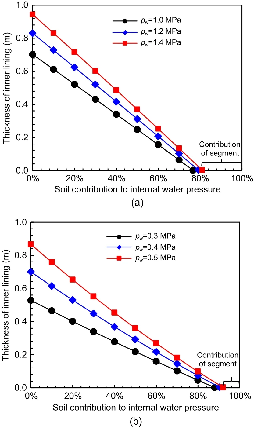
Fig.24 Thickness of inner lining given the variation of soil contribution: (a) strength control standard;(b) deformation control standard
5 Conclusions
In this study,model tests are conducted to inves‐tigate the mechanical responses of double-lining struc‐tures under the conditions of sandy soil and of highly weathered argillaceous siltstone.The soil contribution and its influence on the bearing capacity of the doublelining structure are analyzed.An analytical solution for the double-lining structure is proposed to further inves‐tigate the variation in the soil contribution to the inter‐nal water pressure with the elastic modulus of the soil.The following conclusions can be drawn from the results of the model test and the analytical solution.
(1)The double-lining model is designed in terms of similar material,circumferential joint,and lining–lining interface.The double-lining model is similar to the prototype in its tension stiffness and can simulate the mechanical behaviour of double-lining during the elastic and damage stages.
(2)The proposed analytical solution takes into account the axial stiffness of the segmental lining influ‐enced by the circumferential joint and the reduced axial stiffness of the inner lining after cracking.The average error between the model test and the analytical solution is approximately 7.9%,which verifies the accuracy of the proposed analytical solution.The ana‐lytical solution can reflect the interaction between soil–double-lining and the contribution of soil.
(3)Before the double-lining cracks,the contribu‐tion to the bearing capacity of the tunnel is 3.7%for the sandy soil;it increases to 10.4%for the highly weath‐ered argillaceous siltstone.As a result,the double-lining cracks when the internal water pressure is 0.33 MPa under sandy soil,while it cracks at 0.40 MPa under highly weathered argillaceous siltstone.
(4)After the double-lining cracks,the soil plays a more vital role in bearing internal water pressure.The contribution increases to 10.5%for the sandy soil,and 27.8% for the highly weathered argillaceous silt‐stone.Thus,the ultimate bearing capacity of doublelining rises from 0.70 to 0.97 MPa when the soil con‐dition changes from sandy soil to highly weathered argillaceous siltstone.
(5)The contribution of soil to the bearing capacity increases with the elastic modulus of soil.As the elas‐tic modulus of soil increases to 3 GPa in the elastic stage and 500 MPa in the damage stage,the contribu‐tion of soil reaches about 20%,which should be con‐sidered at the design stage.
Acknowledgments
This work is supported by the Innovation Program of Shanghai Municipal Education Commission(No.2019-01-07-00-07-456 E00051),the National Natural Science Foundation of China (Nos.51978517,52090082,and 52108381),and the Shanghai Science and Technology Committee Program(Nos.21DZ1200601 and 20DZ1201404).
Author contributions
Dong-mei ZHANG designed the research.Xiang-hong BU,Jian PANG,and Wen-ding ZHOU conducted the model test for double-lining and processed the corresponding data.Jian PANG and Xiang-hong BU wrote the first draft of the manuscript.Yan JIANG,Kai JIA,and Guang-hua YANG helped to organize the manuscript.Dong-mei ZHANG and Xiang-hong BU revised and edited the final version.
Conflict of interest
Dong-mei ZHANG,Xiang-hong BU,Jian PANG,Wending ZHOU,Yan JIANG,Kai JIA,and Guang-hua YANG declare that they have no conflict of interest.
 Journal of Zhejiang University-Science A(Applied Physics & Engineering)2022年11期
- Journal of Zhejiang University-Science A(Applied Physics & Engineering)的其它文章
- Visualizing the dynamic progression of backward erosion piping in a Hele-Shaw cell
- Evaluation of heavy roller compaction on a large-thickness layer of subgrade with full-scale field experiments
- Frozen sand–concrete interface direct shear behavior under constant normal load and constant normal height boundary
- Shaking table tests on a cantilever retaining wall with reinforced and unreinforced backfill
- Model test of the mechanism underpinning water-and-mud inrush disasters during tunnel excavation in sandstone and slate interbedded Presinian strata
- Influence of groundwater level changes on the seismic response of geosynthetic-reinforced soil retaining walls