
Design and analysis of a hypersonic inlet with an integrated bump/forebody
2019-12-19 02:20:36ShangchengXUYiWANGZhenguoWANGXiaoqiangFANXingyuZHAO
CHINESE JOURNAL OF AERONAUTICS 2019年10期
Shangcheng XU, Yi WANG, Zhenguo WANG, Xiaoqiang FAN, Xingyu ZHAO
Science and Technology on Scramjet Laboratory, College of Aerospace Science and Engineering, National University of Defense Technology, Changsha 410073, China
KEYWORDS
Hypersonic inlets;
Inlet start;
Integration design;
Method Of Characteristics(MOC);
Separation zone
Abstract Numerical simulations and experiments showed that bump inlet had a remarkable effect on boundary layer diversion of supersonic flow. However, the design and analysis of bump in hypersonic flow was still few.In this paper,the mechanism of a supersonic bump inlet is introduced to the design of hypersonic forebody. A hypersonic inlet with an integrated bump/forebody is obtained by the Method Of Characteristics (MOC) based on a chin inlet. Numerical simulations show that the modified inlet achieves diversion of low-speed flow. Besides, the integrated bump/-forebody is also beneficial to inlet start. During the starting process, the shape of the separation zone is rebuilt by the modified forebody surface which makes spillage much easier.This new design leads to a reduction of the self-start Mach number by 0.95.
1. Introduction
A boundary layer is formed on a fuselage due to the effect of viscosity.1,2Ifalargeamountofthe low-speedflow oftheboundary layer enters the inlet,the efficiency of the combustor will be reduced,and it will also have an adverse effect on inlet start.
Many numerical simulations and experiments indicated that bump inlet had a remarkable effect on diversion of the boundary layer in supersonic flow.3-6Bump played a role as a diversion system of the boundary layer due to the transverse pressure gradient on the bump surface.7The performances of bump inlet were analyzed in supersonic flow,and it was found that bump inlet could divert the boundary layer and reduce the total pressure loss effectively.8,9Masud and Akram studied the performances of bump inlet in supersonic flow and subsonic flow,respectively.10Results showed that bump inlet had excellent performances on total pressure recovery and diversion of the boundary layer.11In general, the design and analysis of bump inlet in supersonic flow have been well researched,and bump inlets have been applied to various supersonic aircraft.12-14
However, the designs and analyses of bump in hypersonic flow were still few. Numerical simulations showed that supersonic bump would produce a strong shock wave if directly applied in hypersonic flow, which caused too much total pressure loss.
To solve these problems, the mechanism of supersonic bump is introduced to hypersonic inlet forebody design, in which the transverse pressure gradient is set by the Method Of Characteristics (MOC) on the forebody to divert the boundary layer. The integrated bump/forebody can avoid strong shock and high total pressure loss. This new design method is applied to a normal chin hypersonic inlet.Boundary layer diversion and flow parameters, especially starting abilities, are studied and compared between original and modified inlets.
2. Model design
2.1. Original inlet
A chin inlet is employed as the original inlet, which is named Case A in this paper. As shown in Fig. 1, the forebody is axisymmetric with a diameter of 631 mm.The cowl is installed on the forebody with a 90° center angle. The length of the whole model is 1600 mm, and the total contraction ratio(CRtotal) and the internal contraction ratio (CRin) of the inlet are 6.0 and 1.9, respectively. Symmetry and osculating planes are displayed in the front and top views. θ is the center angle from the symmetry plane to the corresponding osculating plane. What’s more, the forebody in every osculation plane can be divided into two parts, i.e., the shock-dependent area and the isentropic compression area. In addition, the original inlet is designed at Mach 6.0, and achieves the shock-on-lip to capture as much airflow as possible at the design condition.
2.2. Modified inlet
The modified inlet which is named Case B is obtained based on the original inlet. To avoid affecting the conical shock, the transverse pressure gradient is set on the isentropic compression area,acting a role as the supersonic bump.The new isentropic compression should not affect the conical shock, so these two inlets would capture the same amount of air.By controlling the isentropic compression curve in different osculating planes along the transverse direction, modification of the forebody is realized.
Fig. 1 Diagram of original inlet.
The MOC is employed to design the compression curve in every osculating plane as shown in Fig. 2. Line AB represents the conical shock,and line BB′is tangent to line AB at point B.The shock-dependent area and the isentropic compression area in the osculating plane are the area of ABC and the area downstream BC, respectively. The shock-dependent area of the modified inlet is similar to that of the original inlet. By contrast, the isentropic compression area is redesigned, which is composed of a cluster of Mach waves. Each Mach wave is designed by the MOC, and the bisection method is used to adjust the static pressure of the wall in order to ensure that the Mach wave from the wall is matched with the corresponding discrete point in BB′.
Fig.2 Solution of flow field in osculating plane based on MOC.
A different distribution of these Mach waves achieves different pressure distributions along the flow direction. The Mach wave distribution factor k is defined by Eq.(1),in which rBis the distance from B to the axis, and LBB′is the length of BB′. Thus different controllable Mach wave flow fields are obtained by controlling the value of k. For example, with a decrease of k, the wall pressure rises.
To form a transverse pressure gradient, different k are selected in every osculating plane, which are defined by Eq.(2)with kmin=0.1 and kmax=1.2.Besides,k of the modified inlet is corrected so that the distribution of k is smooth, as shown in the black rectangle frame of Fig. 3.
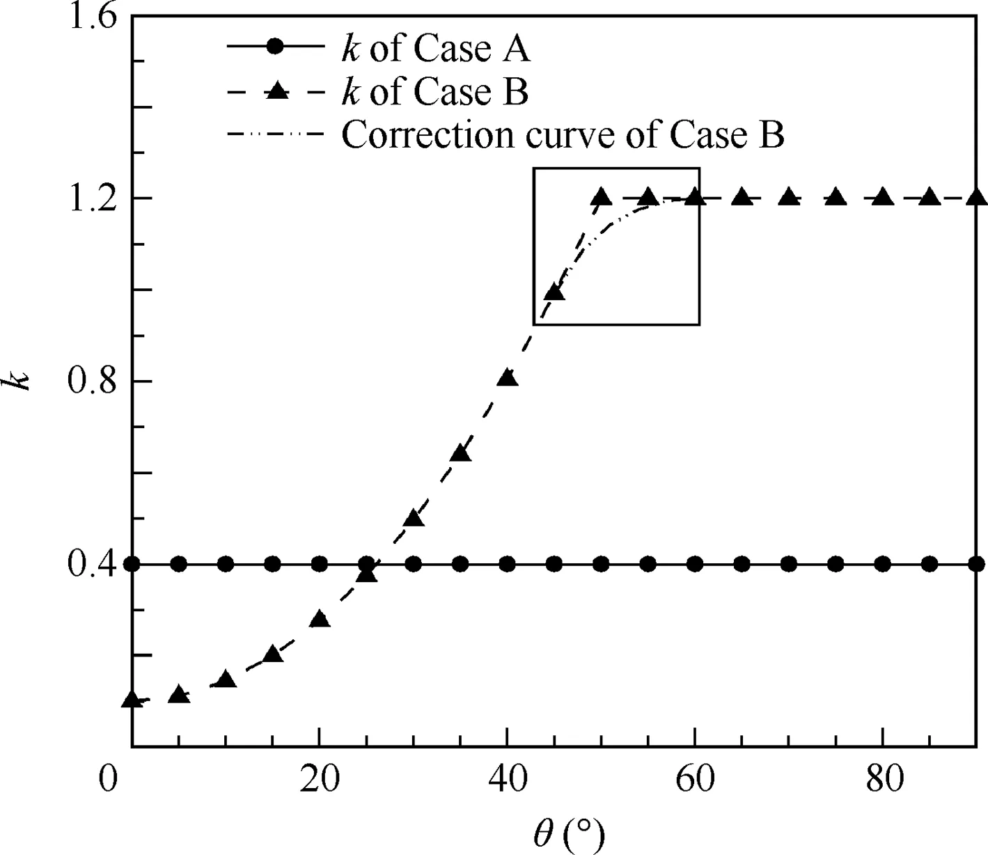
Fig. 3 Distributions of k of original inlet and modified inlet in transverse direction.
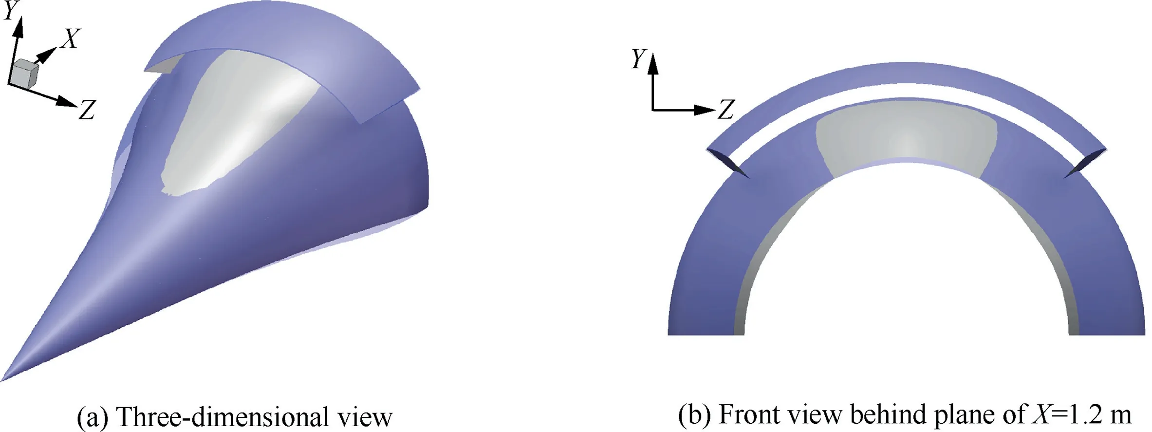
Fig. 4 Comparison of shapes between original inlet and modified inlet.
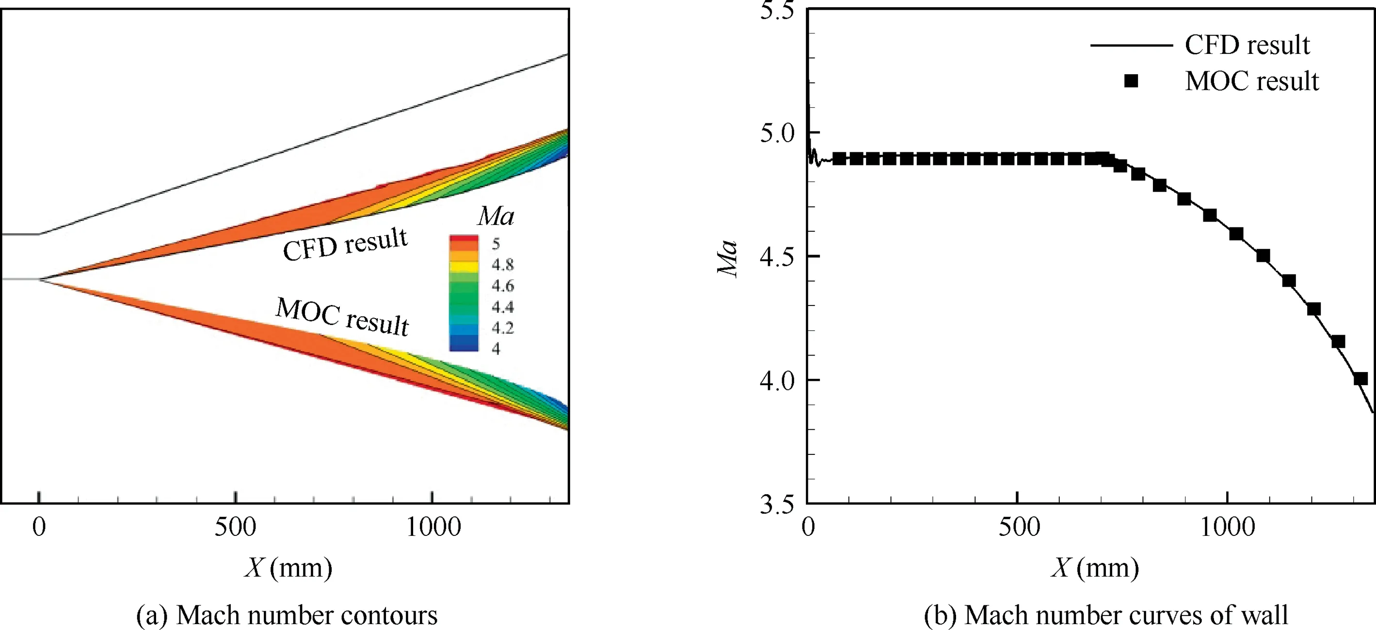
Fig. 5 Mach number distributions of flow field calculated by MOC and Fluent at Ma=6.0.
The two inlets have the same throat and cowl,ensuring that CRtotalof the two inlets are equal. Besides, CRinof Case A is constant within every osculating plane (1.90), while that of Case B increases gradually along the transverse direction with the minimum 1.72 and the maximum 2.47. Fig. 4(a) clearly shows the difference between the two inlets, in which the purple model represents the original inlet and the grey one is the modified inlet. Fig. 4(b) shows the surfaces of the two models at X=1.2 m. Obviously, the wall of the modified inlet is higher than that of the original inlet near the symmetry plane and lower than that of the original inlet on both sides.It means that the modified inlet forms a slim and integrated bump on the forebody compared to that of the original inlet.
2.3. Validation of MOC
In order to confirm the reliability of the MOC used in the design, the wall obtained by the MOC is calculated by the CFD software Fluent with inviscid flow. Fig. 5(a) shows the Mach number (Ma) contours of the flow field calculated by the MOC and Fluent,respectively.Meanwhile,the Mach number curves on the walls of the two flow fields are also compared as shown in Fig. 5(b). It shows that the two results agree with each other very well, which validates the precision of the MOC.
3. Numerical modeling
3.1. Computational method and boundary conditions
The performances of the original inlet and the modified inlet at the design condition and during the self-starting process are researched by viscid numerical simulation. The fluid is modeled as ideal gas. The simulations are carried out using the density-based solver. The two-equation Standard k-ε as a turbulence model, is employed in the simulations to solve the three-dimensional compressible Reynolds-Averaged Navier-Stokes (RANS) equations. The piecewise-polynomial method is selected to compute specific heat, and viscosity is solved using the Sutherland law. The residuals are monitored to ensure convergence of the numerical solution.Structured grids are employed for calculation.The grid distribution on the wall is shown in Fig. 6. To ensure the accuracy of the turbulence flow solution,a value of y+below 0.25 is realized for the main portion of the wall flow region.
No-slip boundary condition and adiabatic condition are enforced at the wall. Far-field flow boundary condition is used at the inlet of the computation region. Pressure boundary condition is applied at the outlet of the computation region. Symmetry boundary condition is used in the symmetry plane.
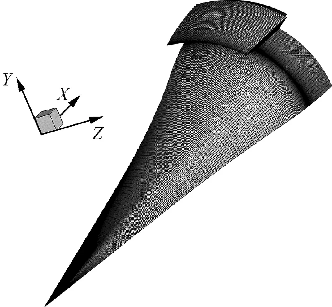
Fig. 6 Grid distribution on wall.
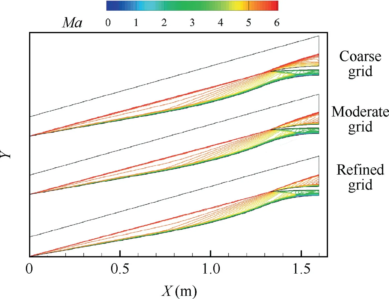
Fig. 7 Comparison of Mach number contours among three different grid scales.
3.2. Grid independency and model validation
In order to investigate the grid independency of the numerical simulations, a two-dimensional grid independency analysis is performed in the symmetry plane. Three different grid scales are compared,namely the coarse grid(160×50),the moderate grid(240×80),and the refined grid(360×120).Fig.7 depicts the Mach number contours under the three scales of grids.It is clear that the grid scale makes a slight difference on Mach number distributions. In addition, with the number of grids increasing, the conical shock waves are getting closer to the cowl lip. Fig. 8 shows the velocity profiles near wall, where the black line represents the sonic line. It is found that the velocity profile near wall of the coarse grid is rough, and that of the moderate grid is almost similar to that of the refined grid. Therefore, the moderate grid is chosen to carry out the following simulations, and the scale of 3D grid is about 1910000.

Fig. 8 Velocity profiles near wall with three different grid scales.
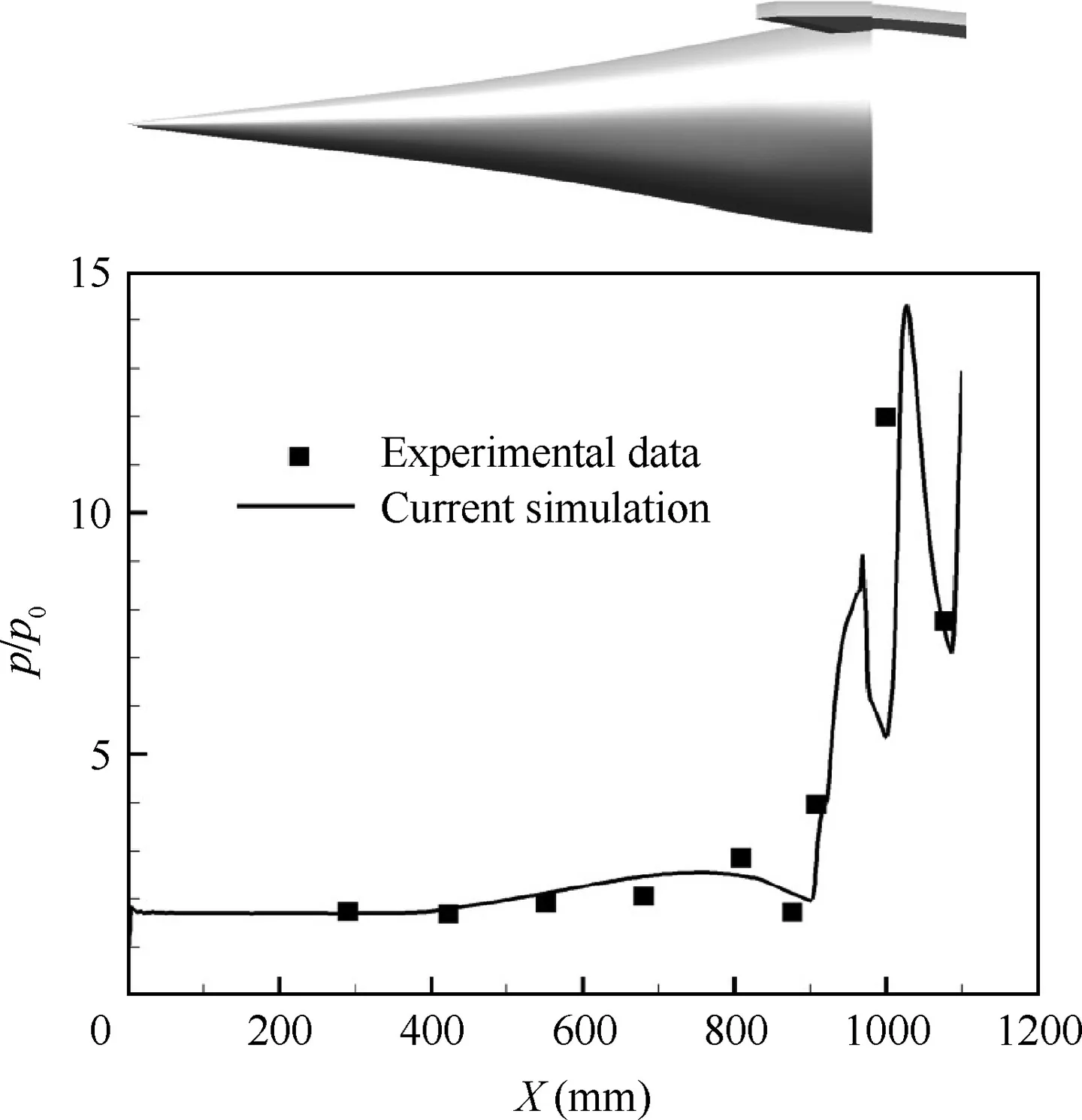
Fig. 9 Comparison of wall pressure ratio distributions between current simulation and experimental data.
The numerical simulation method was validated based on a chin inlet. An experiment was done in a wind tunnel at Ma=4.0. Fig. 9 shows the distributions of the wall pressure ratios(p/p0,p0is the static pressure of far field flow)in the symmetry plane obtained by the experiment and the numerical simulation. This level of agreement in the wall static pressure distribution could put confidence in resolving the model in this paper.
4. Results and discussion
4.1. Diversion of low-speed flow
Fig.10 shows the static pressure contour lines on the forebodies of the two inlets at Ma=6.0.As the modified inlet which is Case B in the figure integrates the bump with the forebody, a transverse pressure gradient is formed on the forebody surface compared to that of the original inlet.
To evaluate the impact of the transverse pressure gradient on the low-speed flow, the velocity (V) contours at the plane of X =1.2 m near the symmetry plane are shown in Fig. 11.The contour lines of the low-speed flow of Case B are lower than those of Case A. For example, the height of the line V=1611 m/s of Case B is 16.81% lower than that of Case A, and the height of the line V=1432 m/s of Case B is 16.32% lower than that of Case A. It is proven that the lowspeed flow of the modified inlet is smaller than that of the original inlet near the symmetry plane.

Fig. 10 Static pressure contours on forebodies of two inlets at Ma=6.0.
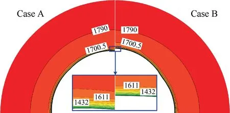
Fig. 11 Velocity contours at plane of X =1.2 m of two inlets.
4.2. Inlet performances at design condition
The performances of the original inlet and the modified inlet at the design condition are analyzed in this paper.Table 1 shows flow parameters at the throat. The two inlets capture almost the same amount of air. What’s more, similar numbers can be seen in the Mach number, the static pressure ratio, and the total pressure recovery of the two inlets. This result indicates that the modified inlet achieves almost the same performance as that of the original inlet at the design condition.
4.3. Self-starting process
Inlet start is an important factor in inlet design. Whether an inlet can start successfully has a strong impact on the performance of a ramjet/scramjet.15-20Self-starting processes of the two inlets are studied and compared. Fig. 12 shows the flow ratios in the process of accelerating. With an increase of the Mach number, the flow ratios (φ) of the two inlets increase slowly, and then the flow ratio of Case B rapidly increases at Ma=4.85 and it starts, while Case A starts at Ma=5.8.The Mach numbers (Mat), pressure ratios (pt/p0), and total pressure recovery (σt) at throats are shown in Fig. 12(b)-(d),respectively. All these results reveal that the modified inlet achieves a better self-starting performance. Therefore, it can be concluded that the modification of the forebody is particularly beneficial to the inlet start.
Furthermore, the Mach number contours of the two inlets are compared during the accelerating start process.In Fig.13,the symmetry plane is selected to display the flow structures in the start process. The separation shock wave of Case A is on the outside of the cowl lip at Ma=4.5. Besides, large-scale separation zones are formed, which cause high flow loss and great changes of main flow parameters at the throat.A similar flow structure can be seen in Case B. With the Mach number rising to 4.8,the separation shock waves of two inlets are close to the cowl lip.In addition,the separation shock wave of Case A is slightly stronger than that of Case B. However, there is a sudden change in the Mach number contours of Case B at Ma=4.9, in which large-scale separation disappears. It is obvious that Case B has already started, while Case A still keeps its unstarted state. With a further increase of the Mach number, the conical shock waves are close to the lip for both inlets. Besides, the separation zone of Case A moves back and becomes small. It can be seen that Case A starts at Ma=5.8,in which the flow structure is similar to that of Case B.When the Mach number increases to 6.0 which is the design condition, the conical shock intersects with the cowl lip for both inlets.Small-scale separation zones are formed in internal contraction sections caused by the interaction between the lip shock wave and the boundary layer.
Based on the analysis above, the start process can be described as follows: the separation shock wave gradually approaches to the cowl lip, the large-scale separation zone moves backward, and then disappears with an increase of the Mach number.

Table 1 Flow parameters at throat.
The streamlines near wall of the two inlets during the accelerating start process are displayed in Fig.14.The two inlets are both unstarted with large-scale separation zones at Ma=4.5 as shown in Fig. 14(a). Besides, it can be seen that spillages are formed for the two inlets.Furthermore,the separation line of Case A shows a two-dimensional shape along the transverse direction near the symmetry plane, while that of Case B changes greatly and is relatively backward. In other words,the separation zone of Case B is smaller than that of Case A. In Fig. 14(b), the two inlets are still unstarted at Ma=4.8, and the streamlines are similar to those at Ma=4.5. As shown in Fig. 14(c), when the Mach number increases to 4.9, there is no obvious difference in the streamlines distribution of Case A.By contrast,the streamlines of Case B change dramatically, in which the separation zone becomes small and the spillage almost disappears. When the Mach number increases to 5.8, the separation zone of Case A becomes small, and the separation line moves back significantly. What’s more, with further increases of the Mach number (Ma=6.0), the streamlines of the two inlets show no obvious difference compared to those at Ma=5.8.

Fig. 13 Comparison of Mach number distributions in symmetry planes during accelerating start process.
The walls static pressure distributions along the transverse direction are extracted with unstarted inlets at Ma=4.5 to study the mechanism of the improvement of the start performance of the modified inlet. Fig. 15 displays the wall static pressure distributions of the original inlet and the modified inlet at the plane of X=1.32 m,in which the dotted black line represents the location of the sidewall.It can be seen that a larger transvers pressure gradient is formed in Case B within the unstart separation bubble.This transverse pressure gradient in case B makes side-moving of subsonic flow in the separation bubble much easier,which leads to a smaller separation region during the starting process.
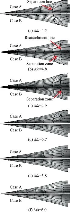
Fig.14 Comparison of streamlines near wall of two inlets during accelerating start process.
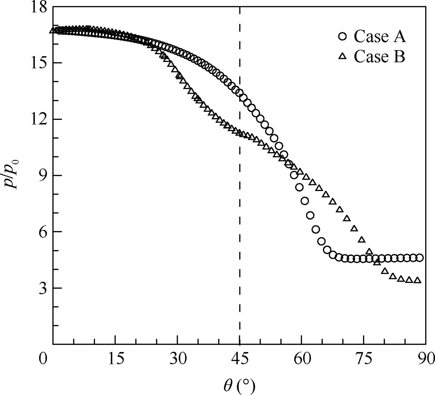
Fig.15 Comparison of static pressure distributions of unstarted inlets along transverse direction at plane of X=1.32 m at Ma=4.5.
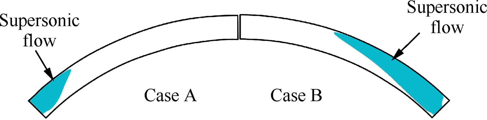
Fig. 16 Comparison of supersonic channels at throats of original inlet and the modified inlet at Ma=4.5.
Fig. 16 shows the supersonic channel at the throats at Ma=4.5. The flow spillage is a critical factor for the establishment of the supersonic channel. The supersonic channel area of Case A accounts for 14.5%, while that of Case B accounts for 38.9%. Obviously, it is beneficial to the start of Case B.
5. Conclusions
The mechanism of supersonic bump inlet is applied to the integration of bump/forebody in a hypersonic inlet. A modified inlet is obtained based on a chin inlet by the MOC.By comparing the performances of the modified inlet and the original inlet, conclusions could be drawn as follows:
(1) The hypersonic inlet with an integrated bump/forebody has the ability to divert low-speed flow.
(2) The modification of the forebody is beneficial to inlet start, in which the self-start Mach number of the modified inlet is 0.95 lower than that of the original inlet.
(3) By analyzing the inlet start process, it is found that the modification changes the shape of the separation zone and increases the flow spillage, which is beneficial to the modified inlet start.
 CHINESE JOURNAL OF AERONAUTICS2019年10期
- CHINESE JOURNAL OF AERONAUTICS的其它文章
- Experimental study of effect of post processing on fracture toughness and fatigue crack growth performance of selective laser melting Ti-6Al-4V
- Efficient and accurate online estimation algorithm for zero-effort-miss and time-to-go based on data driven method
- Experimental and numerical investigation of threedimensional vortex structures of a pitching airfoil at a transitional Reynolds number
- A methodology for simulating 2D shock-induced dynamic stall at flight test-based fluctuating freestream
- Robust adaptive compensation control for unmanned autonomous helicopter with input saturation and actuator faults
- Flight strategy optimization for high-altitude long-endurance solar-powered aircraft based on Gauss pseudo-spectral method