
Investigation on the interface damage in drilling low-stiあness CFRP/Ti stacks
2019-10-26 01:15:34BinLUOKaifuZHANGShunuanLIUHuiCHENGRunxiaoWANG
CHINESE JOURNAL OF AERONAUTICS 2019年9期
Bin LUO, Kaifu ZHANG, Shunuan LIU, Hui CHENG, Runxiao WANG
School of Mechanical Engineering, Northwestern Polytechnical University, Xi'an, Shaanxi 710072, China
KEYWORDS Coupling effects;Drilling;Interface damage;Interlayer gap;Thin walled structures
Abstract Carbon fiber reinforced plastic and titanium alloy (CFRP/Ti) stacks have been widely used as aerospace structures because of their excellent combination of physical properties.Interface damage caused by interface gaps, significantly different from that of metal/metal stacks, is a common problem in the through-hole drilling of CFRP/Ti stacks with low stiffness. In this study, a force-deformation coupling model was developed to further examine the formation mechanism and the control method of interface damage. Firstly, the coupling model was built considering the interaction between the thrust force and the deformation. To solve this model, a numerical method was proposed in which specific cutting coefficients were calibrated using only the thrust force of rigid stacks. Secondly, drilling experiments were performed with different feed rates and bending stiffness. Experimental results indicate that interface damage mainly includes interlayer chips and surface damage of CFRP layers. The surface damage, which is irreparable, is caused by the rotary extension of metal chips along the interlayer gap. Thirdly, variations of the interface gap were calculated with the coupling model that had been verified by measured thrust forces.The damage area was found to have a linear dependence relation with the interlayer gap. However, in conditions of large gap sizes, the interface damage areas increased with the interlayer gap at high feed rates,while decreasing slightly at low feed rates.This phenomenon was satisfactorily explained by the presented model. Finally, a method was proposed to determine the appropriate pressure exceeding which no interlayer damage will occur. Additional drilling experiments proved the method effective.This study leads to further understanding of the forming mechanism of interlayer damage and of selecting appropriate parameters in drilling low-stiffness composite/metal stacks.?2019 Chinese Society of Aeronautics and Astronautics.Production and hosting by Elsevier Ltd.This is an open access article under the CC BY-NC-ND license(http://creativecommons.org/licenses/by-nc-nd/4.0/).
1. Introduction
In modern aircraft manufacturing processes, connecting the thin-wall skin, the stringer, and the frame to the rigid components (e.g. wings or fuselages) is one of the most important procedures.Thousands of holes per assembly are unavoidably drilled for bolting or riveting in the assembly procedure.1Reducing the damage to the holes is crucial to the assembly quality. To achieve higher machining quality and efficiency,the robotic drilling technology has increasingly replaced the traditional manual drilling in the industry.2Components are usually stacked in joint positions and drilled in a single operation of the robotic drilling system. Such one-shot drilling processes not only save time but ensure the proper alignment of the holes on the layers. However, a number of drilling problems emerge in the one-shot drilling of low-stiffness stacked structures, drawing considerable attention from researchers.
Interfacial burrs are a common problem in the throughhole drilling of metal/metal stacked sheets. Removing these burrs needs non-value-added operations, including disassembly, deburring, and reassembly. Experimental results showed that the height of interfacial burrs was reduced when the drilling position was near the clamp, or when the clamping force was acted on the surface of the stacks.3Since the interlayer gap was mainly affected by the clamping force,the thrust force and the bending stiffness,the gap size was considered to have a significant influence on the formation of interlayer burrs.4A number of simplified models were developed to predict the interlayer gap and analyze its influence.5,6The results indicated that decreasing the gap size through preload pressing was an efficient way to control the interlayer burr height to a satisfying value in the drilling of low-stiffness metal/metal stacks.Non-coaxiality was another problem caused by the interlayer gap in drilling stacked structures.7Experimental work and theoretical analyses were conducted to further understand the interlayer gap formations and non-coaxiality occurrences. It was discovered that increasing the clamping force cannot remarkably reduce the gap size when the force was beyond a threshold.The critical clamping force was proposed in the drilling of aluminum stacks, under which both the interlayer gap and burrs were eliminated.8Gao et al.9claimed that using pre-installed fasteners or decreasing the thrust force could also help reduce interlayer gaps and non-coaxiality.
Carbon fiber reinforced plastic (CFRP) has been widely used in the modern aerospace industry, and is usually stacked with metal materials. Among the available configurations,CFRP/Ti(Titanium)coupling is the most popular one because of its excellent combination of metallurgical and physical properties.10CFRP/Ti stacks are considered as typical difficult-to-cut materials, whose drilling damage is very different from that of metal/metal stacks. Special issues may arise from severe subsurface damage,rapid tool wear,and excessive interface defects.11Cutting parameters are optimized to improve the drilling quality. Different cutting parameters are applied to different materials.12,13New materials and special geometry are developed to extend the tool life.14,15According to the drilling experiments of low-stiffness CFRP/Al (Aluminium) stacks, non-coaxiality is observed and tends to be more serious than that of the Al/Al stack.16However,interface damage, similar to interfacial burrs of metal/metal stacks, has not yet been studied for the drilling process of composite/metal stacks.
For any low-stiffness stacks,a high clamping force or a low thrust force helps eliminate interlayer defects caused by the interlayer gaps. A large number of studies developed experimental or theoretical models to determine appropriate clamping forces that match the thrust force and the bending stiffness of the stacks.4-8In effect, the interface gap changes with the dynamic thrust force in drilling stacks. A typical thrust force signal includes several stages according to the cutting materials of drill edges.The variation of thrust forces was ignored in the presented models. In addition, the thrust force is significantly affected by the deformation of work pieces17,18coupled with each other.19Based on this, the modeling of thrust forces and interlayer gaps need to be further studied in the drilling of low-stiffness composite/metal stacks, leading to further understanding of the formation mechanism and the elimination method of interface defects.
This paper studies the coupling law between the thrust force and the structure deformation in the drilling of low-stiffness CFRP/Ti stacks, making possible the exploration of the formation mechanism of the interface gap and the interface damage. A coupling model was first built considering the interactions between the thrust force and the deformation,followed by the presentation of its numerical solution process. A novel calibration method of cutting coefficients was developed independently through drilling tests of rigid stacks. Secondly,experimental works were carried out to study the interface damage and calibrate the coupling model.Thirdly,the verified model was used to predict the variation of the interface gap.Its influence on the formation of the interlayer damage was also investigated. Finally, a method was proposed to determine an appropriate pressure for eliminating the interlayer damage with a minimum deflection of the stacks.
2. Force-deformation coupling model in drilling low-stiffness stacks
2.1. Description of drilling process of low-stiffness stacks
In a rigid stack drilling process, deformation does not occur under the action of thrust forces. The process is divided into three stages according to tool-work interactions: (a) the composite layer drilling stage,(b)the interface region drilling stage,and (c) the metal layer drilling stage, as shown in Fig. 1 (a).There is no gap or damage at the interlayer region. However,deformation affects the relative feed speed between the cutter and the workpiece in the drilling of low-stiffness stacks.19The stage division of the drilling process should consider both interactions and deformation. Four specific moments are defined in the drilling process.‘‘Contact”refers to the moment when the drill edge touches the second layer;‘‘separation”represents the moment when the interaction force of the layers reduces to zero,where deformation of the second layer exceeds that of the first layer;‘‘entrance”denotes the moment when the drill edge fully engages in the second layer;‘‘springback”refers to the moment when deformation of the second layer reduces.Thus,the drilling process of low-stiffness stacks is divided into five stages based on the four specific moments as shown in Fig. 1(b).
In stage I,only the first layer is drilled.The deflection of the two layers is the same and increases over time.In stage II,both layers are drilled. The thrust force of the first layer decreases,while that of the second layer increases.The deflection of each layer differs at the end of this stage. In stage III, both layers are still drilled with the deflection of the first layer reducing to zero while that of the second layer increasing.The interlayer gap occurs and increases. A part of the drill edge does not cut the stack because of the gap.In stage IV,only the second layer is drilled. The deflection of the layer as well as the interlayer gap increases to the maximum. In stage V, the second layer is drilled. Both its deflection and the interlayer gap reduce to zero. The region in which stages II and III occur is named interface region where the drill bit cuts both layers.The thrust force in this region equals the sum of the element forces from each layer.
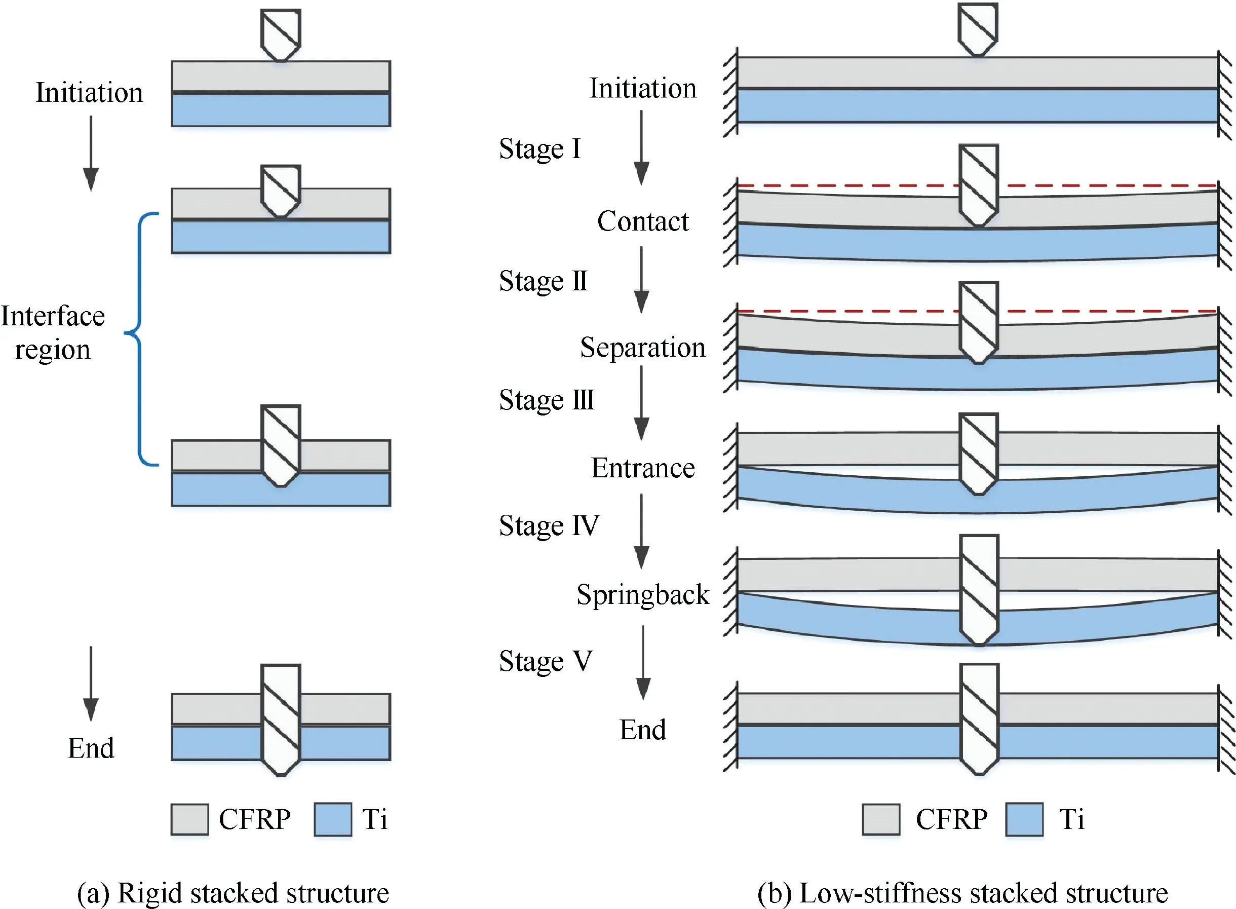
Fig. 1 Multi-stage drilling process.
2.2. Calibration of cutting coefficients
The thrust force in the drilling stack needs to be known before the calculation of the deflection. Since the cutting angles vary along the drill edge, it is difficult to directly model the thrust force. Therefore, the infinitesimal method is proposed, in which the drill edge is divided into small elements. Each element has a constant cutting angle, and is assumed to be orthogonal or oblique cutting. Luis et al. proposed that material removal was the plastic extrusion in the region around the center of the chisel edge, called the indentation zone.20At the remaining portion, material removal was found to be orthogonal cutting with a large negative rake angle.21Since the radius of the indentation zone is much smaller than the chisel length,the orthogonal cutting could be extended to the whole chisel edge.
The cutting force of the element is proportional to the cutting area.The ratio is defined as the specific cutting coefficient(kc), represented through a power law relationship using the uncut thickness and the rake angle and spindle speed.21Our previous work concluded that the law relationship was effective for the drilling process of the CFRP/Ti stacks.22Since the cutting depth is proportional to the feed rate,and the spindle speed has little effect on the thrust force,22the specific cutting coefficient could be expressed as:

where γ is the rake angle of the cutting element, and kc1, kc2,and kc3are the coefficients related to the material property.The complexity of the cutting process leads to the lack of methods to obtain coefficients from the material properties.Therefore,the coefficients are always calibrated through experimental data.
For element M at radius distance r, the elementary forces can be decomposed into the cutting direction (dFc) and the feed direction (dFfd). Thrust force Fthis obtained by summing force dFfdin the axial direction for all the elements, as shown in Fig.2.Then,a simple and effective model of the thrust force can be written as19
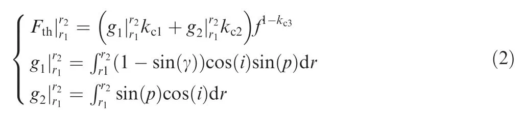
where i is the inclination angle, p the point angle of the drill bit, r the distance of the considered point M on the drill edge from the drill axis, g1and g2are the factors related only to the drill geometry, and r1and r2are the limits of integration, as shown in Fig. 2. Rake angle γ and inclination angle i are calculated using equations in Ref. 22. Since the woven-ply or the cross-ply composite can be assumed as an isotropic material, the cutting force model is effective for the woven CFRP.22
Since the cutting force in the interface region equals the sum of the forces from both layers,the thrust force in the stack drilling (Fth,stk) can be expressed as
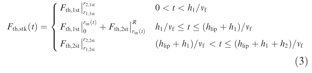
where Fth,1stis the thrust force in the first layer drilling, Fth,2stis the thrust force in the second layer drilling,h1is the height of the first layer, h2the height of the second layer, vfthe feed speed in mm/s, and hlipis the height of the drill edges which is written as
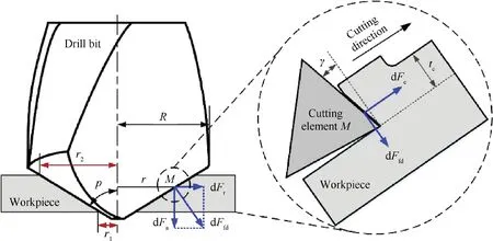
Fig. 2 Calculation of thrust force in drilling process.
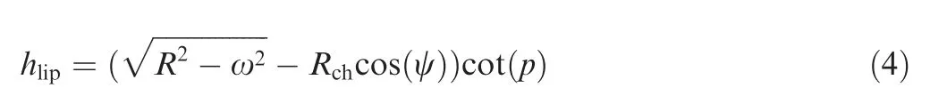
where R is the radius of the drill,Rch denotes half of the chisel length, ψ the chisel angle, and ω is half of the web thickness.If the machining time is set to zero at the moment when the drill bits touch the stack, the maximum radius distance of the drill edges involved in the cutting at time t can be calculated by

Then, the limits of integration in Eq. (3) can be written as
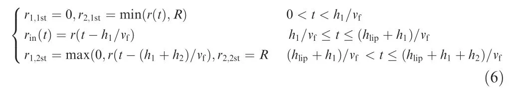
In previous literature, coefficients kc1, kc2, and kc3need to be calibrated from the thrust force of the entrance stage in the single layer drilling process, indicating the necessity of a series of extra experiments. According to Eq. (3), the thrust force in the interface region equals that from both layers.Since the entrance stage is the inverse process of the exit stage in the well supported case, the thrust force of the second layer in the entrance stage could be separated from the stack drilling force. Based on this, a novel method is proposed to calibrate the specific cutting coefficient directly from the stack drilling force:
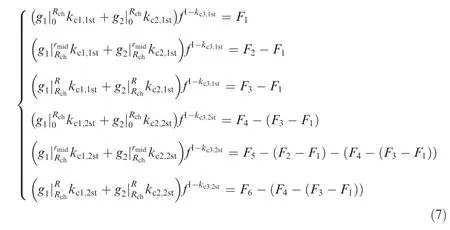
where F1~F3are the thrust forces of the stacks when the integrating ranges are [0, Rch], [Rch, rmid], [Rch, R], respectively,during the drilling in the first layer, and F4~F6are those in the second layer, as shown in Fig. 3. rmidequals (R-Rch)/2.Machining times t1~t6are calculated through Eqs.(5)and(6).
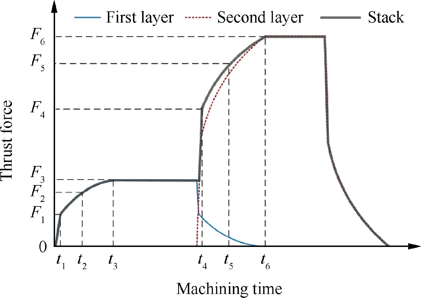
Fig. 3 Calibration of specific cutting coefficients in drilling stacks.
2.3. Method for predicting thrust force and interlayer gap
Since the primary cutting load in the drilling process is applied laterally to the axis of the components, the airframe components are simplified to beams.4,7The mode of deflection is primarily formed through bending. Thin rectangular plates with fixed ends are analyzed in this paper as shown in Fig. 1. It is complicated to obtain an analytical solution for the deformation of this structure. Hence, the finite element method is proposed to calculate the deflection of the stacks. A beam is regarded as an element with a node at each end. Each node undergoes a vertical displacement w and a rotation θ, with two degrees of freedom.The stiffness equation of the beam element can be written in a matrix form:
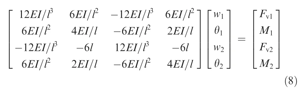
or simply as:

where E is the elastic modulus of the specimen, the area moment of the inertia I=bh3/12, b, h and l are respectively the width,the height,and the length of the stack,and Keis the stiffness matrix relating the nodal displacements matrix qeto the forces matrix Fe.
The global stiffness matrix K and the global force vector F are assembled. If the number of the beam elements is an odd number n,the size of the assembled is 2(n+1).Boundary conditions are given as qr=0 (r=1, 2, 2n+1, 2n+2). Then,the global matrix element krris set to one, krsand ksrare set to zero (s=1, 2, ..., r-1, r+1, ..., n), and Fris also set to zero. The displacement vector is obtained by F/K. When the thrust force is on the geometric center, the deflection at drill point uthequals w(n+1)/2.Bending stiffness KBis defined as

where uthis the deflection at the drilling point.
If the thrust force acts on the first layer, both layers have the same deflection in the fixed end case. Then, the bending stiffness of the stack (KB,stk) equals the sum of the bending stiffness of each layer (KB,1st, KB,2st):

Thrust force Fth,1stslowly reduces while Fth,2stincreases in stage II. When the deflection of the top layer caused by Fth,1stequals that of the bottom layer caused by Fth,2st,the two layers begin to separate. Limit of integration rin(t) is noted as rspat this moment. Then, rspcould be obtained by solving the following equation
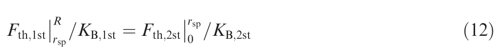
Before separation, the deflection of the two layers is the same, thus the interlayer gap of the stack is zero in stages I and II. After separation, the first layer resiles and the second layer continues bending. The interlayer gap appears in stages III, IV, and V, which can be expressed as
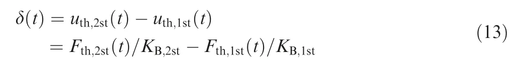
where δ(t)is the interlayer gap,uth,1stthe deflection of the first layer, and uth,2stis the deflection of the second layer.
Bending or release movements change the feed rate f between the drill bit and the stack in Eq. (2). The feed rate of the drill bit is defined as a set value f0.The feed rate is smaller than its set value in the bending stage and larger than that in the release stage. The feed rate in drilling the low-stiffness structure equals the derivation of the deflection subtracted from the set value as follows:19

where nsis the spindle speed in rev/s.
In stages I and II, the deflection of each layer is the same,hence their feed rates are the same (f1st=f2st). Therefore,the stack can be regarded as a single layer plate.By combining Eqs. (2), (3), (10), and (14), the coupling model of the thrust force and the deformation in the drilling of low-stiffness stacks can be written as
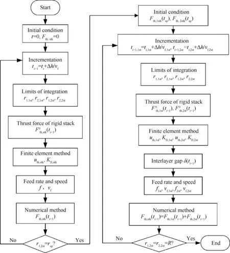
Fig. 4 Calculation process of force-deformation coupling model.
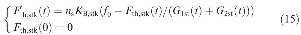
where Fth,stk(0) is the initial condition, and G1st(t) and G2st(t)are noted as
After separation time tsp, the interlayer gap occurs. Part of the drill edges is not involved in the drilling process. The feed rates of each layer are different(f1st≠f2st).The drilling process of the two layers are independent from each other. Therefore,the thrust force can be expressed as
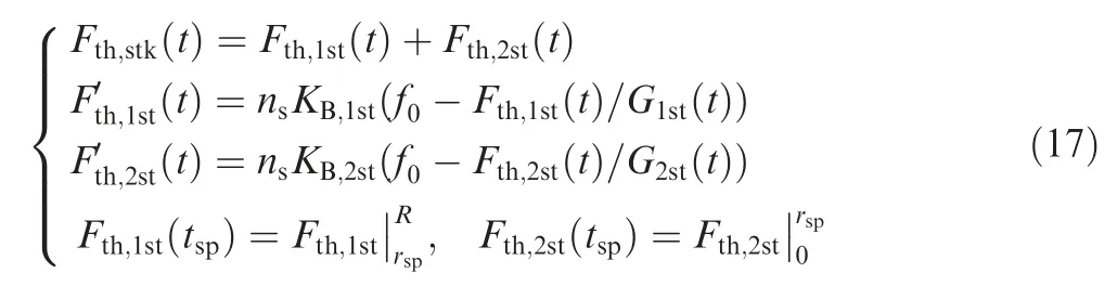
where Fth,1st(tsp) and Fth,2st(tsp) are the initial conditions.
A numerical method is employed to solve Eqs. (15) and(17),since the integration of G1st(t)and G2st(t)are rather complex to solve.Then,the finite element method is used to obtain the deformation of the stack. The solving process of the coupling model is shown in Fig. 4.
3. Drilling experiments of low-stiffness CFRP/Ti stacks
3.1. Description of experimental conditions
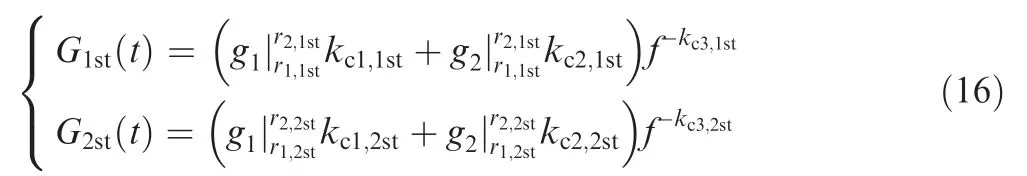
Drilling experiments are carried out to verify the proposed model and study interlayer damage caused by interlayer gaps and cutting chips.Since the feed rate is the key factor affecting the thrust force,and bending stiffness is mainly determined by the length of the structures, the experiments are performed with specimens of different lengths and feed rates. The specimens are stacked into two layers, the first layer being CFRP,and the second Ti-6Al-4V.The CFRP/Ti stacks vary in length,leading to varying bending stiffness. The tool used in the experiment is a carbide twist drill with a straight cutting edge.The drilling point is the geometric center of the specimens with fixed ends. The detailed experimental conditions are listed in Table 1. Three feed rates and four lengths are selected. Zeroin length means the specimen is supported by a plate with an 8 mm diameter hole. In this case, the stiffness of the specimen is large enough so that its deflection can be ignored.
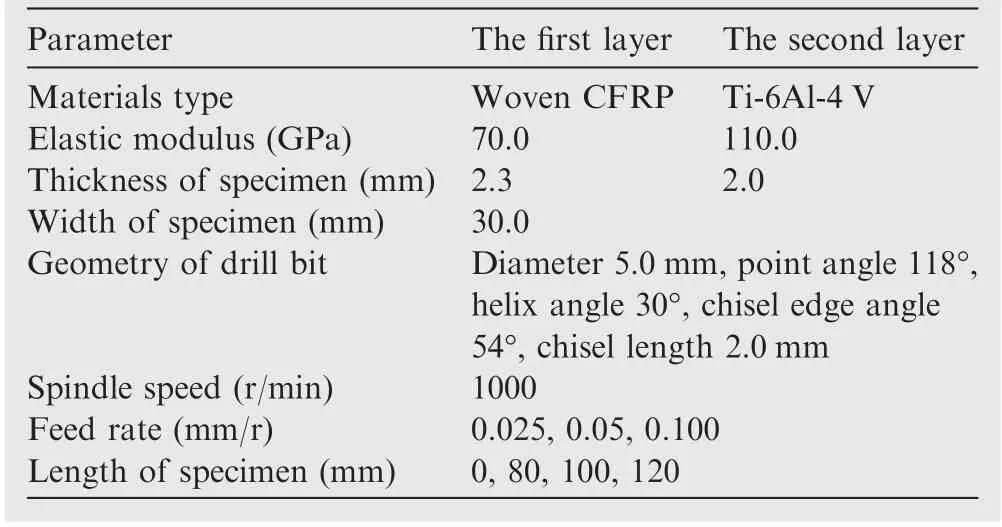
Table 1 Conditions in drilling low-stiffness CFRP/Ti stacks.
The full factorial method is used to design the experiments.Thus, all levels of variates could be investigated. All the tests are dry drilling operations with a constant spindle speed on a CNC milling machine (XKN713). A dynamometer (Kistler 9257A) and a charge amplifier are used to measure the thrust forces. Both ends of the stacks are fixed to the dynamometer by bolts and fixtures. Force signals are collected and saved by a data recorder. Fig. 5 is the experimental setup for the measurement of the thrust force in the drilling of the CFRP/Ti stack.
3.2. Experimental results and calibration of the coupling model
Delamination is known as the main defect in drilling composite laminates. However, it does not appear in stack drilling because of the support of the titanium layer.A camera is used to obtain the damage pictures of the CFRP/Ti stacks. A scale is introduced into the picture according to the hole diameter and the thickness of stacks.As can be seen from Fig.6(a),titanium chips accumulate at the interlayer during the drilling of the second layer of the low-stiffness stacks. The chips scratch and destroy the hole edge of the CFRP layer during the depositing process(Fig.6(b),6(c)),while little damage is found on the surface of the titanium layer (Fig. 6(d)). This is due to the direction of the chip flow, and the higher hardness of the titanium surface. As is shown in Fig. 6, the main interface defects of the low-stiffness CFRP/Ti stacks are the interlayer chips and the surface damage of the CFRP layer. The former can be removed by the reassembly operation,while the latter is irreparable, hence must be avoided.
Fig. 7 shows the effect of bending stiffness (i.e. specimen length) on the thrust force and the interface damage at f0=0.05 mm/r. As the bending stiffness decreases, the increase of the thrust force slows down, while the maximum thrust force reduces about 16%. The edge damage of the CFRP hole deepens with the decrease of the bending stiffness.
Three curves of the thrust forces at l=0 mm are used to obtain forces F1~F6shown in Fig.3.Then,the values are substituted into Eq.(7).The logarithm of both sides and the least square method are employed to solve the equation. The calibration results are listed in Table 2.
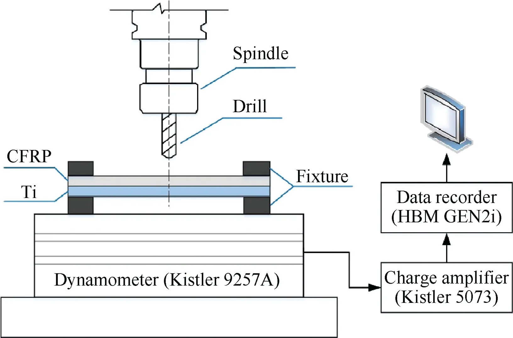
Fig. 5 Experimental setup of thrust force measurement.
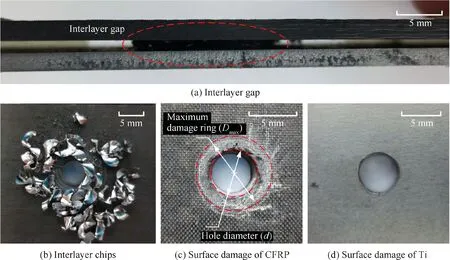
Fig. 6 Interlayer chips and induced damage in drilling CFRP/Ti stacks.
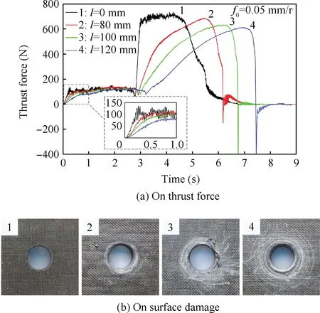
Fig. 7 Effect of bending stiffness.
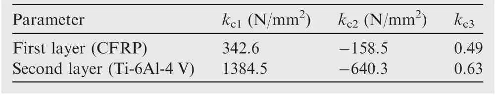
Table 2 Calibration results of specific cutting coefficients.
To quantitatively analyze the influence of experimental conditions on the interface deflects, a damage factor (Id) is identified to evaluate the damage degree as follows:

where D is the diameter of the surface damage zone and d is the diameter of the hole.
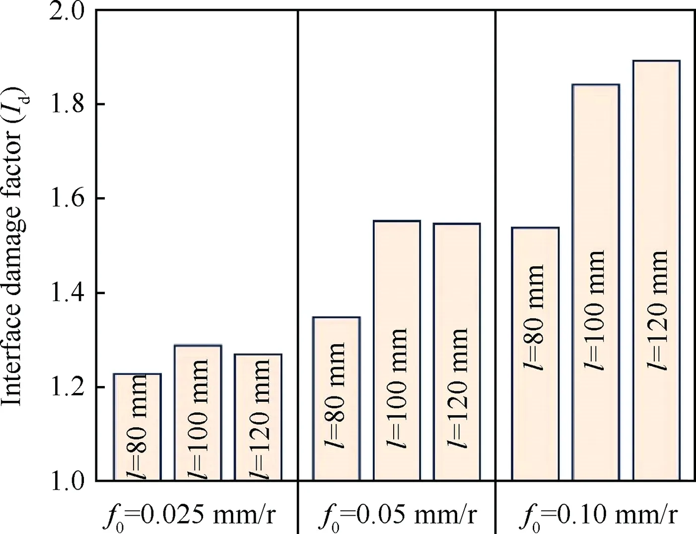
Fig. 8 Interface damage factor varying with feed rates and specimen lengths.
Fig. 8 shows the damage factors at various feed rates and specimen lengths.As is seen from the figure,the average value of factor Idincreases when the feed rate rises from 0.025 mm/r to 0.100 mm/rev. Factor Idincreases significantly when the specimen length increases from 80 mm to 100 mm; however,different tendencies emerge when the length increases from 100 mm to 120 mm. Factor Iddecreases when f0=0.025 mm/r, changes slightly in the case of f0=0.05 mm/r, and increases while f0=0.10 mm/r. The reason is explained in Section 4.2.
4. Results and discussions
4.1. Verification of force-deformation model
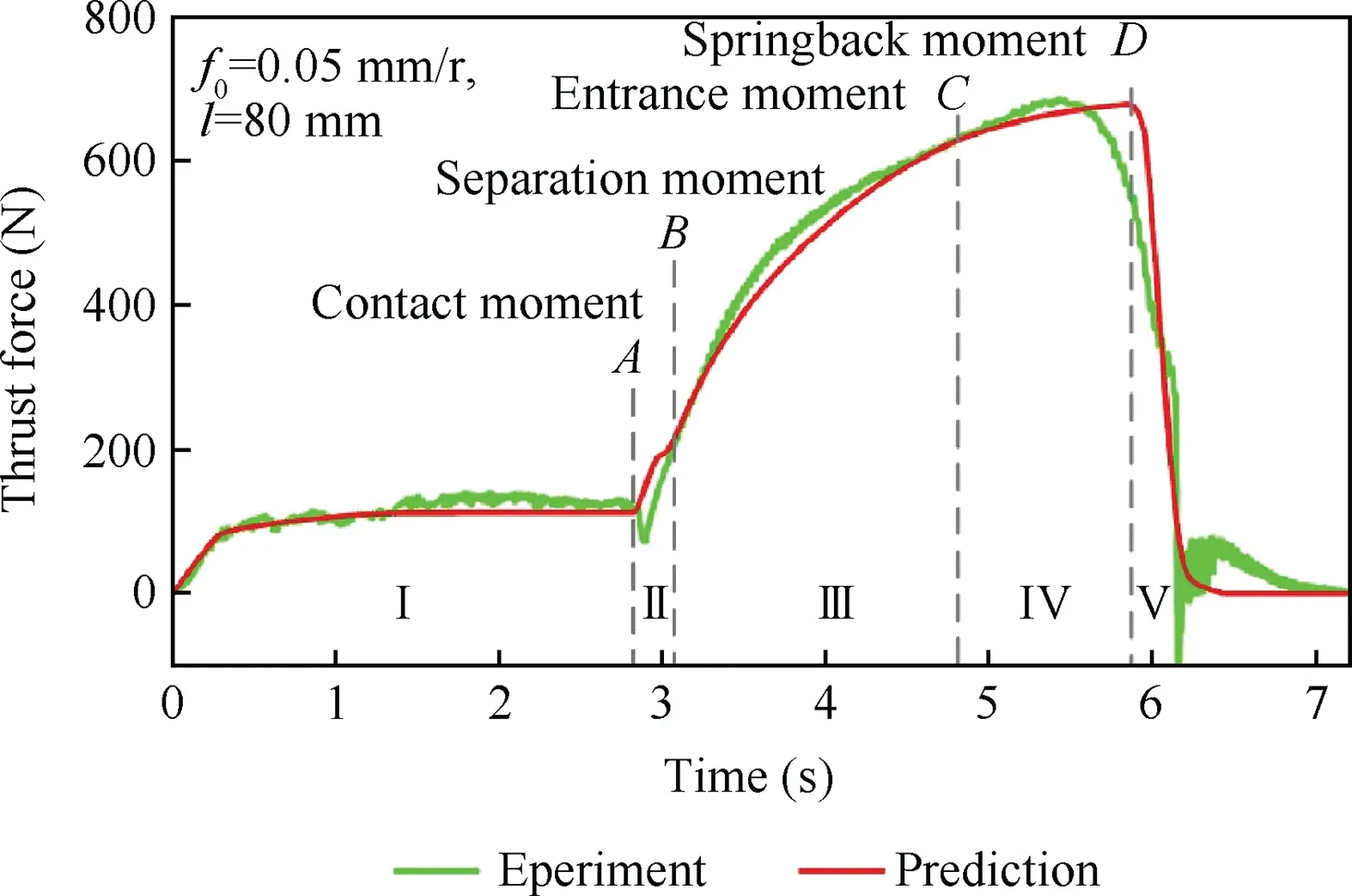
Fig. 9 Experimental and predicted thrust forces of low-stiffness CFRP/Ti stack.
Fig. 9 shows the experimental and the predicted thrust forces under the conditions of f0=0.05 mm/r, l=80 mm. Four specific points and five stages are marked on the force curves.As can be seen in the figure, the two results fit well. The peak value of the thrust force appears at point C and point D,respectively, in the drilling of rigid stacks (Fig. 7) and lowstiffness stacks. The variation of the feed rate is the main reason for this difference. Eq. (2) indicates that the thrust force relates to the integration interval[r1,r2]and the feed rate when the material of the stacks and the geometry of the drill bit are the same. Interval [r1, r2] of the second layer increases during stages II and III, remains constant in stage IV, and decreases in stage V.If the feed rate is invariable,the thrust force reaches its maximum value at point C, and then slightly reduces in stage IV, causing local deformation around the drill bit in the feed direction. However, for low-stiffness stacks, the feed rate is smaller than its set value due to the bending movement in stage IV, and is higher due to the resilience movement in stage V(Eq.(14)).Since the stack recovers within a short time,the effect of the interval[r1,r2]reduction is higher than that of the feed rate increase. Thus,the peak value of the thrust force appears at point D.
Deviations of the experiment from the prediction exist around point D and in stage II. The first deviation is caused by the local deformation in the feed direction which brings forward springback moment D. Solving Eq. (12) shows that radius distance rspis smaller than chisel radius Rch, revealing the occurrence of the separation during the short time when the chisel edge cuts into the second layer. Theoretically, the chisel edge cuts into the second layer immediately after penetrating the first layer. In the zero length case, the decline of the force in stage II indicates the existence of a protrusion on the lower surface of the first layer (Fig. 7) caused by the plastic deformation around the drill bits.Practically,however,the chisel edge touches the second layer after breaking through the protrusion, causing a time delay between the two actions.It brings forward separation moment B (Fig. 9). Therefore,the reason for the second deviation is the small protrusion at the interface.
According to Fig. 4, the calibrated coefficients in Table 2 are used to calculate the thrust force and the interlayer gap of low-stiffness CFRP/Ti stacks. The predicted thrust forces are compared with the experimental data in Fig. 10. The two groups of forces have the same trend and the same peak magnitude in all the cases.The predicted error of the peak value is within 8%,indicating a good agreement between the predicted and the experimental thrust forces. The force-deformation coupling model is effective in predicting the thrust force.Since deformation has a strong interaction effect with the thrust force,the proposed coupling model is also valid for predicting the deflection of the stack.
4.2. Interlayer gap and its effect on interlayer damage
Since the hole is drilled at the geometric center of the CFRP/Ti stack, the height of the interlayer gap is the largest at the drilling location. Fig. 11 shows the maximum height of the gap varying with the machining time. The gap forms during stage III, and reaches the maximum at the moment just before the drill cuts out of the stack instead of the moment when the drill edge fully cuts into the second layer. With the decrease of bending stiffness, both the maximum value and the appearing time of the interlayer gap increase considerably,while the peak value of the thrust force slightly reduces. Therefore, a higher value of the interlayer gap will be obtained when using the thrust force measured under a well supported condition.
In the drilling process, continuous chips obliquely move upward between the wall of the hole and the drill flutes.When the interlayer gap appears in stages III and IV,the chips of the titanium alloy crash into the hole edge and the low surface of the CFRP layer,subsequently divided into two parts.One part moves along the drill flutes to be removed, and the other extends vortically along the gap scratching the lower surface of the CFRP layer. With the increase of the interlayer gap,the scratch area increases, the chips of the titanium alloy silt more, and the damage around the CFRP surface deepens(see Fig. 7).
The height of the interlayer gap reaches its maximum value at the‘‘springback”moment(Fig.9).Sections of the interlayer gap at that moment are shown in Fig. 12, when feed rate f0equals 0.05 mm/rev. Since the interface damage is caused by the movement of the metal chips along the interlayer gap,the damage factor should be proportional to the gap size if the titanium chips are sufficient.At a high feed rate,the experimental results agree with our analysis. However, the damage factor decreases at a large gap size when the feed rate is low(Fig. 8). In the case of a large gap size, the metal chips should be strong enough to exert necessary destructive power on the CFRP layer.Considering the influence of both the attenuation of the destructive power and the flow direction of the metal chips, the effective damage zone of the metal chips is similar to an ellipse. Since the destructive power of the metal chip increases with its thickness, the size of the similar ellipse zone increases with the feed rate. Therefore, the similar ellipse is small at a low feed rate. The damage area of the CFRP layer is within the overlap region of the CFRP surface and the similar ellipse,whose location rises in the similar ellipse zone with the increase of the interlayer gap.In the case of a low feed rate and a large gap, the interlayer gap will be higher than the widest location of the similar ellipse, thus the damage factor decreases (Fig. 12). While under the condition of a large gap and a high feed rate, the interlayer gap is still lower than the widest location of the similar ellipse in all cases. The damage time of the chip increases near the hole edge, while decreases in the outer range in the case of a large gap.This is the reason why the damage factors show different tendencies when the length increases from 100 mm to 120 mm (Fig. 8). Nevertheless, the damage of the CFRP surface deepens though its area lessens,because the damage time of the chip is longer at a large interface gap (Fig. 7).
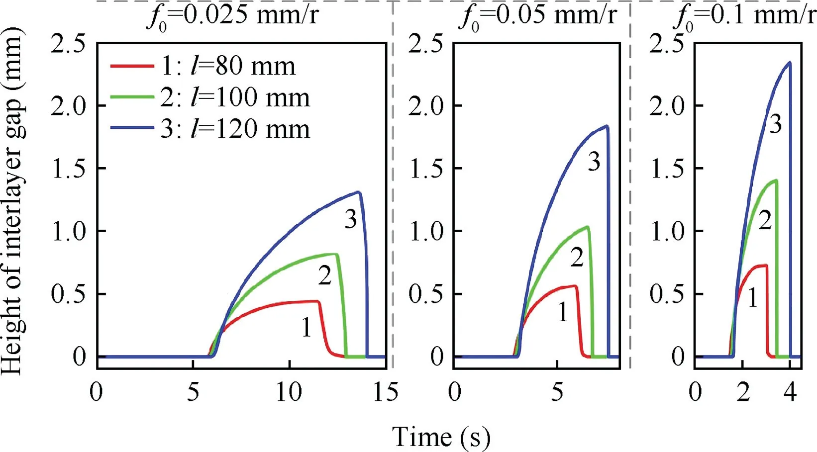
Fig. 11 Maximum height of interlayer gap varying with drilling parameters.
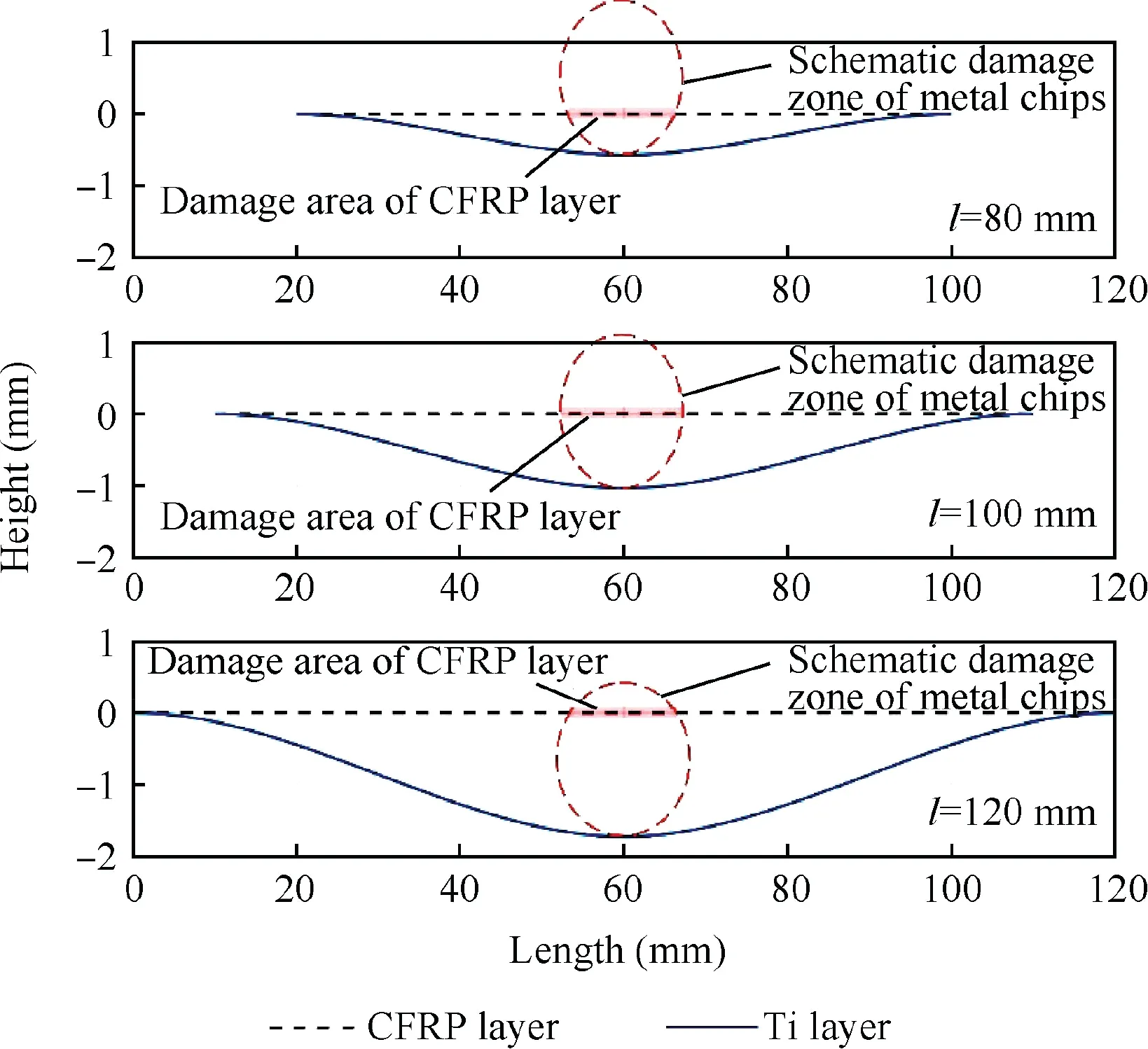
Fig. 12 Interlayer gap and schematic damage zone at different lengths.
Though the damage factors show different tendencies with the interlayer gap, the interface damage is still significantly affected by the interlayer gap in the drilling of low-stiffness stacks.5,6Results of the correlation analysis indicate a linear dependence relation between damage factor Idand the interlayer gap as shown in Fig. 13, hence, reducing the interlayer gap is an effective way to control the interface defect.
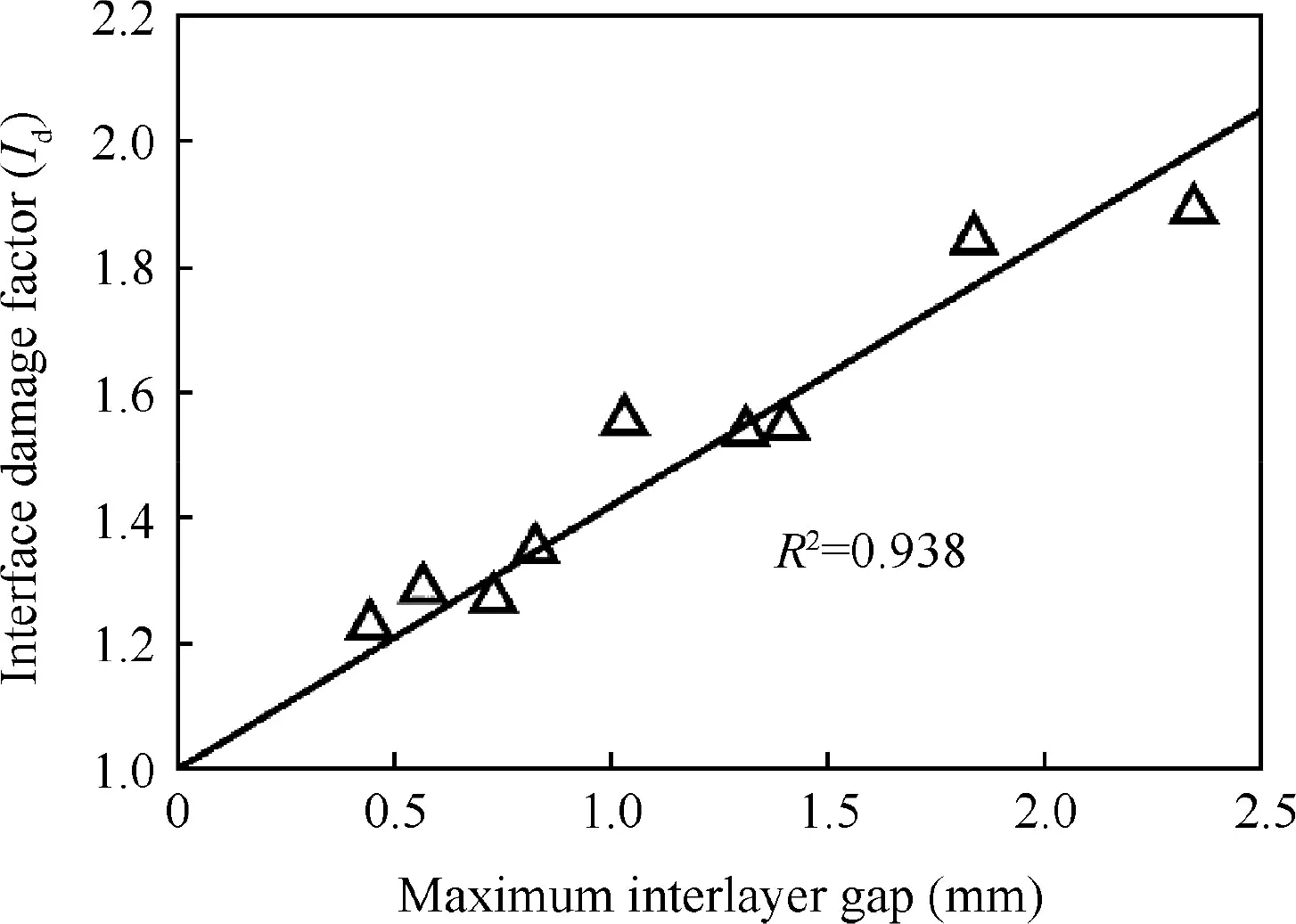
Fig. 13 Linear regression curve for interface damage factor and interlayer gap.
4.3. Control of interface damage by clamping foot
Effects of the cutting parameters and the continuous chips on the interlayer damage will be attenuated when the interlayer gap is sufficiently small.The gap could be reduced by selecting a low feed rate.However,this method leads to production efficiency loss. Though increasing bending stiffness could also reduce the interlayer gap, the structure of the fixture needs to be redesigned,which is both time-consuming and expensive in aeronautical manufacturing fields. Another method widely used in robotic drilling systems is to exert pressure upon the surface of the stack through a nosepiece, as shown in Fig. 14. An annular area is a typical contact area between the stack and the nosepiece, whose diameter of the center line(d)is 10 mm.The pressure value should be within an appropriate range, below which the interface defect cannot be eliminated, while beyond this range, the deformation would be too large to result in a bell hole.
Since diameter d is small compared to the length of the stack, pressure Fp is assumed to be a concentrated force. To ensure the stability of the drilling process, the nosepiece holds still after the pressure rises to the set value. Then, predeflection δ0caused by Fpcan be expressed as

To eliminate the interlayer gap, the pre-deflection needs to be larger than the deflection of the second layer in the whole drilling process. Inequality Eq. (20) should be met:

Critical pressure Fp0is defined as the minimum pressure,beyond which no gap exists.

When l=80 mm and f0=0.05 mm/rev,the maximum gap is 0.56 mm,and the critical pressure is 1142 N.Three pressures below the critical value are selected to investigate the influence of pressures on the drilling process. The clamping force is exerted through bolts, and measured by a round gasket force sensor (Kistler 9133B). Fig. 15 shows the thrust force and the interlayer damage at different pressures 143, 408, and 1081 N. Pre-deflections for each pressure are 0.07, 0.20, and 0.53 mm, respectively. In stage IV, about 3~5 s of Fig. 15(a),the integration interval [r1, r2] identically equals to [0, R].The thrust force varies with the feed rate according to Eq.(2). When the pressure is close to or higher than the critical value,Eq.(14)indicates that the feed rate is a constant,which means the thrust force is also a constant as shown in Line 4 of Fig. 15(a). However, when the pressure is lower than the critical value,the feed rate is firstly smaller than its set value,then increases to the set value. Hence, the thrust force increases as shown in Lines 1, 2, and 3 of Fig. 15(a).
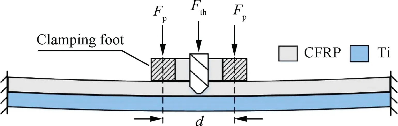
Fig. 14 Pressure acting on the stack through a clamping foot.
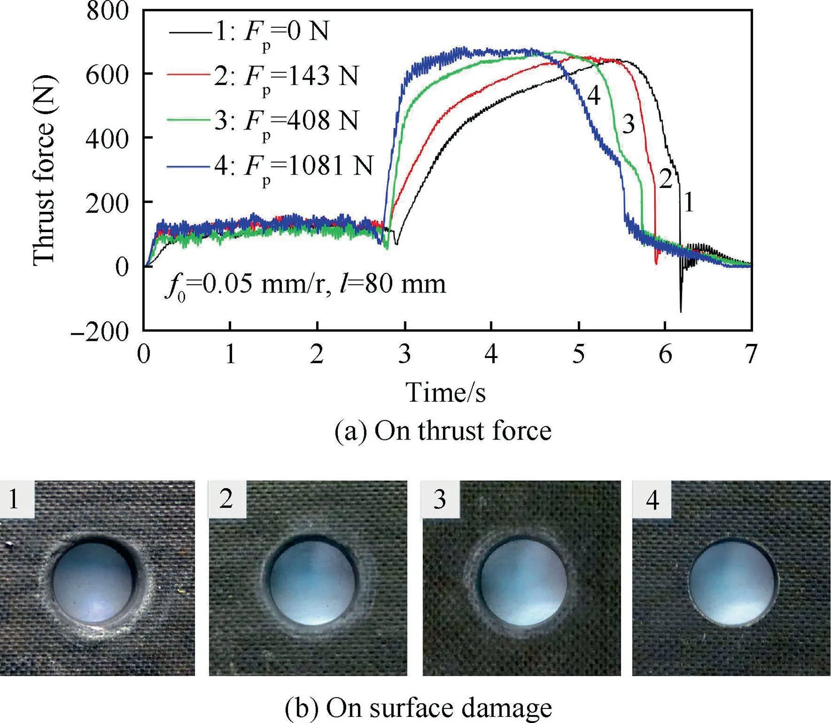
Fig. 15 Effect of foot pressure.
As seen from Fig. 15, the quality of the interlayer is improved with the increase of pressure,because both the magnitude and the lifespan of the interlayer gap reduce. A significant reduction in the interface damage is observed under a very small pressure (143N). In addition to the reduction of the gap size,another reason is that the clamping foot prevents the first layer from bending upward, caused by the metal chips at the interface. At pressure 1081N, which is close to the critical value, the interlayer gap still exists. However, no interface defect is observed in this case,because the gap size is too small for the titanium alloy chips to crash into.
5. Conclusions
For the drilling process of low-stiffness CFRP/Ti stacks, this paper investigated the force-deformation coupling law, the formation and the control of the interface defects.It is possible to draw the following conclusions from the present work:
(1) A coupling model has been proposed to describe the interaction between the thrust force and the deformation of the layers in the drilling of low-stiffness stacks, in which specific cutting coefficients are calibrated using only the drilling force of rigid stacks. The predicted and measured thrust forces have the same trend, and the predicted error of the peak value is within 8%. This proves the validness of the coupling model.
(2) The drilling process of the low-stiffness stack is divided into five stages based on four specific moments. The interlayer gap forms during stage III, reaching its maximum value at the moment just before the drill cuts out of the stack, instead of the moment when the drill edge fully cuts into the second layer.Both the peak value and the lifespan of the interlayer gap increase with the reduction of bending stiffness.
(3) The surface damage of the CFRP layer and the interlayer chips are the main types of interlayer defects during the drilling of low-stiffness CFRP/Ti stacks. The damage is caused by rotary extensions of the metal chips along the interlayer gap. Damage factor Idis identified to evaluate the irreparable surface damage. Results of the correlation analysis indicate that factor Idhas a linear dependence relation with the interlayer gap(R2=0.938).
(4) Damage factor Idincreases with the interlayer gap at a high feed rate, and decreases at a low feed rate, when the gap size is large. The effective damage zone of the metal chips is similar to an ellipse whose size increases with the feed rate.At a low feed rate,the damage factor decreases because the maximum interlayer gap would be higher than the widest location of the similar ellipse.
(5) Imposing pressure on the surface of the stack by a clamping foot proves effective in reducing the interface damage, because the pressure can reduce both the magnitude and the lifespan of the interlayer gap. Then, a method is presented to determine an appropriate pressure for the elimination of the interlayer damage with the minimum deflection of the stacks.
In future work,a novel finite element method will be developed to analyze detailed deformation of complex structures in the drilling process. Then, both the physical damage and the geometrical error can be modeled for the accurate assembly of complex thin-wall structures.
Acknowledgments
This study was co-supported by the National Natural Science Foundation of China (Nos. 51705426 and 51475379) and the Key Research and Development Plan of Shaanxi Province of China (No. 2017GY-101).
 CHINESE JOURNAL OF AERONAUTICS2019年9期
- CHINESE JOURNAL OF AERONAUTICS的其它文章
- Fast Track
—— New Column Launched by CJA - Eあect of stress ratio on HCF and VHCF properties at temperatures of 20°C and 700°C for nickel-based wrought superalloy GH3617M
- Sealing reliability modeling of aviation seal based on interval uncertainty method and multidimensional response surface
- A linear ADRC-based robust high-dynamic doubleloop servo system for aircraft electro-mechanical actuators
- Cardinality compensation method based on information-weighted consensus filter using data clustering for multi-target tracking
- Area-oriented coordinated trajectory planning of dual-arm space robot for capturing a tumbling target