
Transient temperature and pressure calculation model of a wellbore for dual gradient drilling *
2018-09-28 05:34:36XueruiWang王雪瑞BaojiangSun孫寶江PingyaLuo羅平亞ZhiyuanWang王志遠NingWang王寧KeKe柯珂HuiZhang張輝
水動力學(xué)研究與進展 B輯 2018年4期
Xue-rui Wang (王雪瑞), Bao-jiang Sun (孫寶江), Ping-ya Luo (羅平亞), Zhi-yuan Wang (王志遠),Ning Wang (王寧), Ke Ke (柯珂), Hui Zhang (張輝)
1. School of Petroleum Engineering, China University of Petroleum (East China), Qingdao 266555, China
2. State Key Laboratory of Oil and Gas Reservoir Geology and Exploitation Engineering, Southwest Petroleum University, Chengdu 610500, China
3. SINOPEC Research Institute of Petroleum Engineering, Beijing 100101, China
Abstract: During deep-water oil and gas explorations, the dual gradient drilling (DGD) technology provides solutions to problems caused by the narrow density window and the shallow gas by controlling the pressure profile in the wellbore. A transient temperature calculation model is established with consideration of the heat generated by the pump in the specific processes of the DGD systems.Besides, the momentum equation is modified by considering the lift force of the pump on the drilling mud in the pressure calculation.An iterative scheme for the coupled temperature and pressure calculations is developed. Besides, the transient temperature and pressure are analyzed for a deep-water well in South Sea. It is shown that the bottom-hole pressure varies significantly with the transient temperature in the wellbore, and the change of the bottom-hole pressure in the case of the DGD (626 kPa) is larger than that in case of the conventional drilling (115 kPa) due to the constant inlet pressure of the subsea pump. With this fact in mind, an adequate safety margin is strongly recommended to be considered during the hydraulic parameter design of the DGD. Our results further show that the DGD can significantly extend the operation range of the drilling fluid density, and the advantage becomes more obvious in a deep water.
Key words: Dual gradient drilling (DGD), transient, temperature, pressure
Introduction
As the offshore oil and gas exploration gradually migrates into deeper seas, several technical problems caused by the deep water drilling become increasingly prominent[1]. The deep water drilling usually needs more casing strings due to the small difference between the pore pressure and the fracture pressure. As a result, the diameter of the well hole is considerably small, which increases the complications and the cost of the drilling processes. At the same time, the small diameter of the production tubing may constrain the flow rate. The deep water drilling is also facing other risks, such as the seabed instability, and the shallow gas and shallow water flows. The dual gradient drilling (DGD) technology provides solutions to the aforementioned problems by employing the managed pressure drilling (MPD) method, which generates two or more types of pressure gradients in the annulus to control the pressure profile. Various commercial DGD systems including the subsea mudlift drilling (SMD),the riserless drilling (RD) and the Maxlift drilling system are utilized in the deepwater oil and gas industry[2]. Among them, the SMD system has been developed for a long time since the later 1996. A field application of the SMD system was made on the Diamond New Era to drill a test well in the Green Canyon 136 (a location provided by Texaco) on August 24, 2001 and all SMD operations were tested and completed by October 14, 2001[3]. In the DGD system, the annulus of the conductor is filled with sea water, and the returned mud is transported through a bypass line in a return line of smaller diameter[3-4]. A mudlift pump is used to pump the returned mud back to the platform, and the inlet pressure of the pump remains equal to the hydrostatic pressure of the sea water. Thus two pressure gradients are generated in the annulus[5].
The key to the DGD technology is to precisely control the bottom-hole pressure. The temperature profile of the deep water drilling process is complex because the temperature near the mudline is low while the bottom-hole temperature is much higher. Accordingly, affected by temperature and pressure, the density and the viscosity of the drilling fluid vary greatly in the wellbore, and in turns, the wellbore pressure and temperature will be affected. In order to estimate the bottom-hole pressure accurately, coupled calculation models for the wellbore temperature and pressure with a high precision are desirable. Besides,the temperature in the wellbore is equal to the environment temperature initially, and starts to change and reach a steady state after starting the circulation.The bottom-hole pressure will also change with the temperature due to the change of the density and the viscosity of the drilling fluid. The change of the bottom-hole pressure is an issue to be studied in the DGD system in order to control the bottom-hole pressure precisely. Thus a transient thermal model of a wellbore for the DGD should be established. In conclusion, the accurate prediction of the temperature and the pressure plays an important role in the hydraulic parameter design and the overflow prevention for the DGD technology.
Most of the studies of the DGD technology focus on the system components and the process, without paying enough attention to the temperature and pressure calculation model of the wellbore. This paper establishes a transient temperature and pressure calculation model for the DGD systems, which is related with the following challenging issues:
(1) The flow path of the drilling fluid within the DGD system is quite different from that of the traditional drilling systems, which makes the heat transfer process very complicated. Besides, the heat generated by the pump might influence the temperature profile of the system.
(2) Due to the installation of the subsea pumps,the traditional momentum equation should be modified to consider the work done by the pump in the pressure calculation. We need a coupled solution of the transient temperature and pressure.
The wellbore temperature and pressure calculation models were developed for a long time. After the 1990?s, Hasan and Kabir[6-7]carried extensive studies to develop wellbore temperature calculation models.Since then, most of the models and their applications[8-9]. about wellbore temperature were on the basis of Hasan and Kabir? work The calculation of the pressure field of the DGD systems without consideration of the temperature is a simple process.Jonggeun[10]calculated the pressure field of a riserless drilling system.
With the SMD system as an example, this paper establishes a transient temperature calculation model of a wellbore for the DGD in view of the specific processes of the DGD systems, and the heat generated by the pump is considered in the established model.Besides, the momentum equation is modified by considering the lift force of the pump on the drilling mud in the pressure calculation. An iterative scheme for the coupled temperature and pressure calculations is developed. The transient temperature calculation is validated via a real field case and the pressure calculation of the model is validated by comparing the results against the data from a case in literature. Also,the model is used to analyze a deep-water well in South Sea. The transient temperature and pressure are analyzed through the case study in this paper.
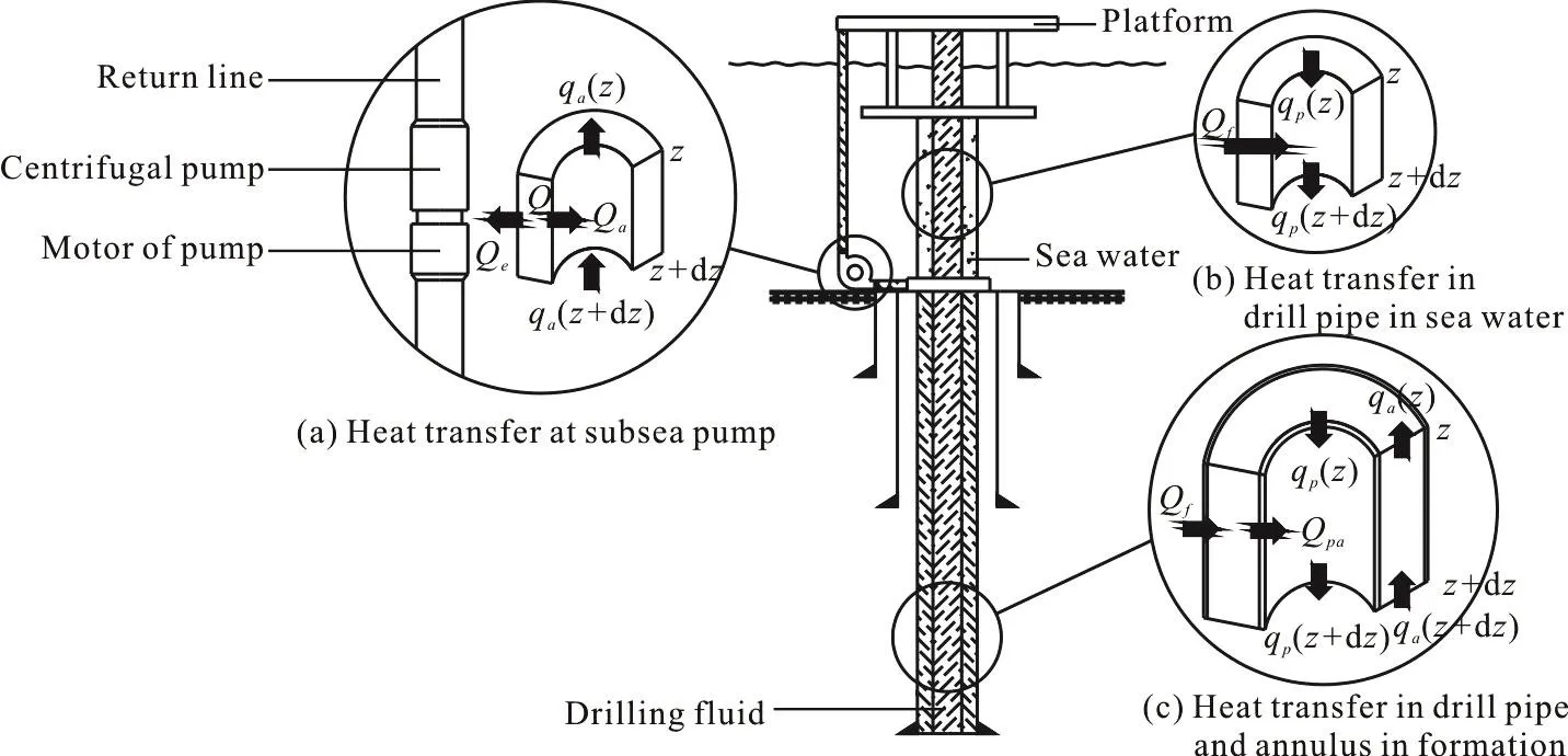
Fig. 1 Flow path and heat transfer in the SMD system
1. Transient temperature and pressure calculation model for the DGD system
1.1 Transient temperature calculation model for the DGD system
With the SMD system as an example, it is seen that the flow path of the drilling fluid in the SMD system is quite different from that of the traditional drilling system. Figure 1 shows the drilling fluid entering the wellbore in the drill pipe and returning to the annulus in the formation. The drilling fluid then flows through the subsea pump at the mudline and then into the return line. The calculation process includes the following three parts:
(1) The temperature profile in the return line.
(2) The temperature profile in the drill pipe in the sea water.
(3) The temperature profile in the drill pipe and the annulus in the formation.
The heat transfer process is illustrated in Fig. 1.
(1) In the return line, the heat is transferred between the drilling fluid in the return line and the sea water. Furthermore, when the drilling fluid flows through the subsea pump, the heat generated by the pump motor would affect the temperature of the drilling mud.
(2) In the drill pipe sunk in the sea water, the heat is transferred between the drilling fluid and the sea water.
(3) In the drill pipe and the annulus in the formation, the heat is transferred among the drilling fluid and the drilling fluid in the annulus and the formation. Consequently, we need to combine the equations of the drill pipe temperature with that of the annulus in the formation.
The following assumptions are made in the temperature field calculation.
(1) The flow of the drilling fluid in the wellbore is one-dimensional.
(2) The heat loss in the direction of the wellbore is ignored and only the radial heat loss is considered.
(3) The entire heat produced by the motor of the pump is transferred to the drilling fluid in the return line and the surrounding sea water.
(4) The distance between the return line and the conductor is large enough so that there is no heat transfer between them.
1.1.1 Energy equation with consideration of the heat produced by the pump
When the drilling fluid flows through the subsea pump, the heat produced by the pump motor will be transferred to the drilling fluid to change the temperature of the drilling fluid. For instance, an SMD system uses a submersible centrifugal pump with a structure and a heat transfer process illustrated in Fig.1(a).
The heat generated by the pump motor can be described as

where Q is the heat produced from the pump motor,Npis the input power of the pump motor, η is the efficiency of pump motor.
Figure 1(a) shows the heat produced by the pump motor and transferred to the drilling fluid in the return line and the surrounding sea water. According to the energy conservation, the heat transferred to the surrounding sea water and the drilling fluid can be defined as follows:
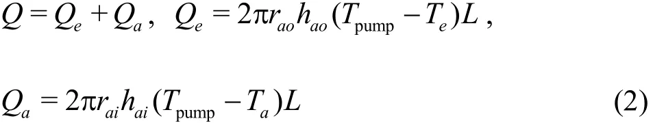
where Qeis the heat transferred to surrounding sea water, Qais the heat transferred to drilling fluid, raois the outside diameter of return line, raiis the internal diameter of return line, haois the convective heat transfer coefficient between sea water and the outside wall of return line or pump, haiis the convective heat transfer coefficient between drilling fluid and the inside wall of return line or pump, Tpumpis the temperature of the wall of pump, Teis the ambient temperature (sea water temperature or formation temperature), Tais the temperature of drilling fluid in return line, L is the length of pump.For the convective heat transfer between the sea water and the outside wall of the pump, haocan be determined as[11]
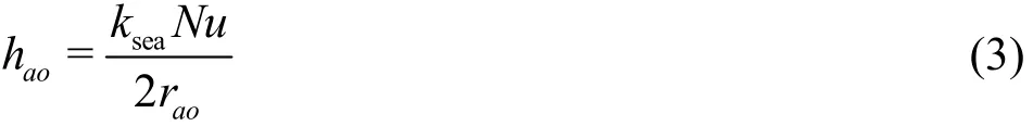
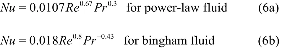
where kseais the sea water conductivity, Nu is the Nusselt number, and can be calculated as

where Pr is Prandtl number, Re is Reynolds number.
For the convective heat transfer between the drilling fluid and the inside wall of the pump, haican be determined as[11]
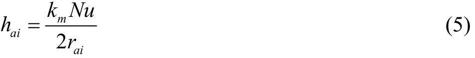
where kmis drilling mud conductivity, Nu is the Nusselt number, and can be calculated as
The heat transferred to the drill fluid can be determined by eliminating Tpumpfrom Eqs. (2), (1)
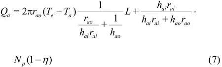
The overall heat transfer coefficient Uais used to describe the thermal resistance in a series from the drilling fluid in the pump to the sea water,including the heat convection between the drilling fluid and the inside wall of the pump, the heat conduction of the pump wall, and the heat convection between the sea water and the outside wall of the pump. Compared to the heat convection, the heat conductivity of the pump wall steel is considerably higher, which can be neglected. The overall heat transfer coefficient Uacan be expressed as Ua=. When the Uexpression isaapplied to Eq. (7), the heat transferred to the drill fluid can be rewritten as

where, the first item in the right hand side of Eq. (8)represents the heat transfer between the sea water and the drilling fluid, which is usually negative, and the second item in the right hand side of Eq. (8) indicates the heat transferred from the pump to the drilling fluid.
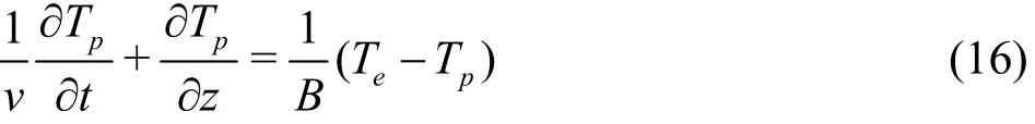
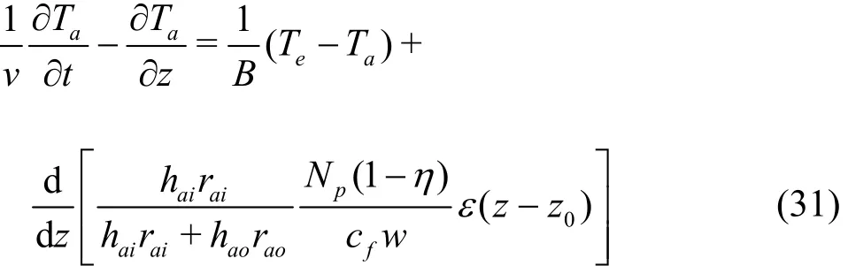
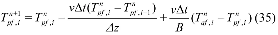
The heat change in a unit body is equal to the heat inflow minus the heat outflow, then the energy equation with consideration of the heat produced by the pump can be written as
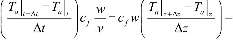
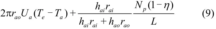
where Δt is the difference between two adjacent time modes, cfis the specific heat capacity of drilling fluid, w is the mass flow, v is the velocity of drilling fluid, Δz is the distance between two adjacent space modes.
1.1.2 Temperature calculation equation in the return line
The length of the subsea pump is denoted as L,and the pump is located at the positions from z=z0to z=z0+L. The heat transferred from the pump to the drilling fluid along the return line can be describes as:
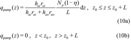
where z is distance from the wellhead.
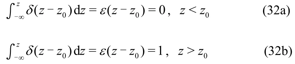
The unit impulse function is also called the Dirac function δ(z-z0), which is used to describe a quantity focused at a point. The unit impulse function has the following properties:
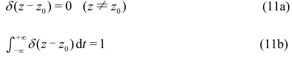
The size of the subsea pump is negligible comparing to the length of the return line. Therefore,ignoring the pump length we may say that it is located at one point z=z0. The heat transferred from the pump to the drilling fluid along the return line can be obtained by introducing the unit impulse function in Eq. (10)
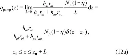
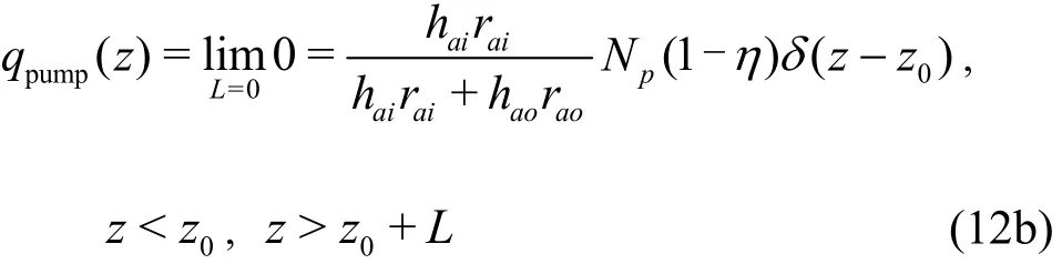
As a result, the return line energy equation with consideration of the heat generated by the pump can be obtained as
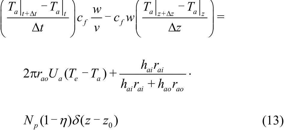
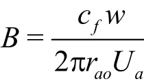
Equation (13) can be rewritten in a finite differential form by taking the limitation of the left hand side
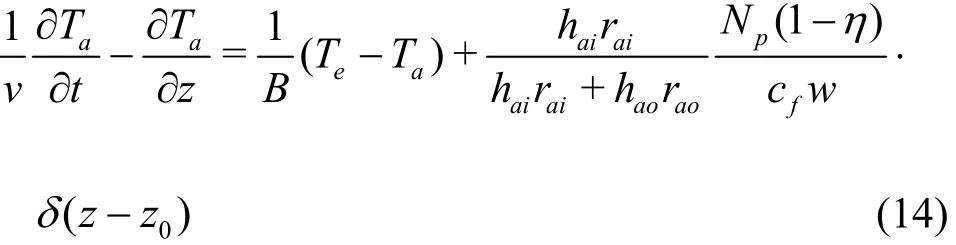
where
1.1.3 Temperature calculation equation of the drill pipe in the sea water
Figure 1(b) shows that the heat produced in the unit body is equal to the inflow heat minus the outflow heat, therefore the energy equation for the drill pipe in the sea water can be written as
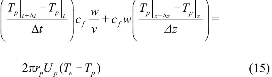
where Upis the overall heat transfer coefficient between sea water and drilling fluid in drill pipe in sea water, Tpis the temperature of drilling fluid in drill pipe in sea water, rpis the outside diameter of drill pipe in sea.
Equation (15) can be rewritten in a differential form as
where
1.1.4 Temperature calculation equation in drill pipe and annulus in formation
The calculation method in the traditional drilling[12-14]can be used for the SMD systems since the heat transfer processes in the formation are very similar. Figure 1(c) indicates the existence of the heat transfer between the drill pipe fluid and the annulus,thus the equations of the temperature in the drill pipe and in the annulus in the formation should be combined.
Hasan and Kabir[6-7]proposed the following algebraic approximation to describe the heat transfer between the annulus and the formation, which is quite adequate for most engineering purposes
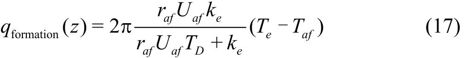
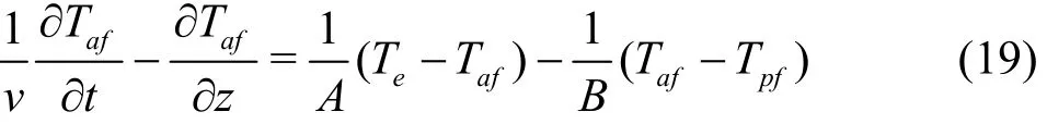
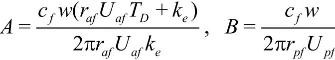
where rafis the outside diameter of annular in formation, Uafis the overall heat transfer coefficient between the annular and formation, keis the formation conductivity, TDis the dimensionless time,Tafis the temperature of drilling fluid in annular in formation.
The heat produced in the unit body is equal to the inflow heat subtracted by the outflow heat, therefore the energy equation in the annulus in the formation can be written as
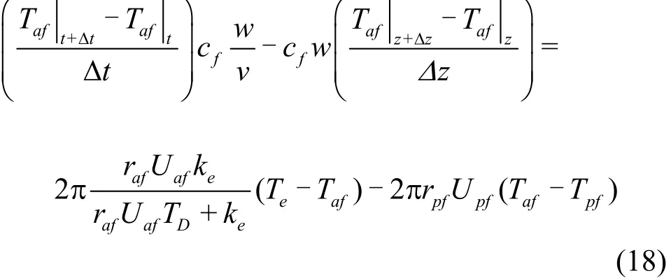
where rpfis the outside diameter of drill pipe in formation, Upfis the overall heat transfer coefficient between drill pipe and annular in formation, Tpfis the temperature of drilling fluid in drill pipe in formation.
Equation (18) can be rewritten in a differential form as
where
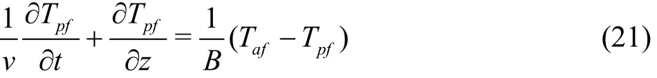
The energy equation in the drill pipe in the formation can be written as

Equation (20) can be rewritten in a differential form as
1.2 Pressure calculation model for the DGD system
Based on the momentum conversation, the force on a particle is equal to the rate of the momentum change of that particle. Then the momentum equation of the fluid in a unit body can be rewritten as follows[15-16]
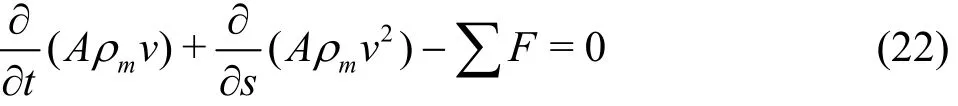
where t is the time after starting the circulation, A is the cross-sectional area,mρ is the density of drilling fluid, s is the distance from the bottom of the well, F is the external forces.
In the DGD system, the external forces should also include the lift force of the subsea pump. The external forces can be described as
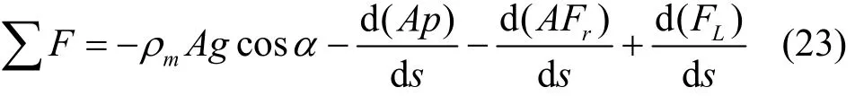
where α is the angle of inclination, g is the gravitational acceleration, p is the pressure, Fris the frictional pressure drop, FLis the lift force of the pump.
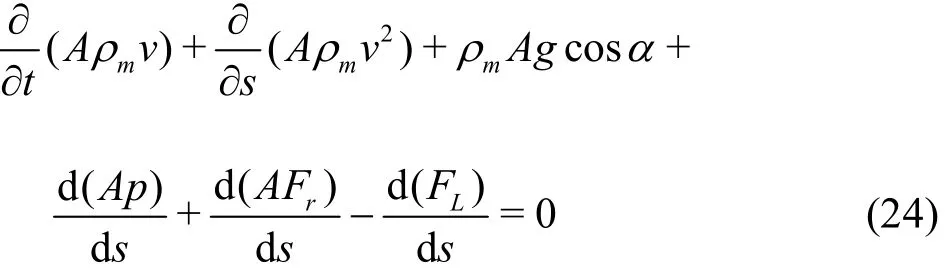
Combining Eq. (22) and Eq. (23), the momentum equation with the pump lift force included can be written as
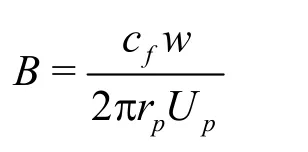
The pump is located at the position s=s0, and one item of the lift force in Eq. (24) can be defined by
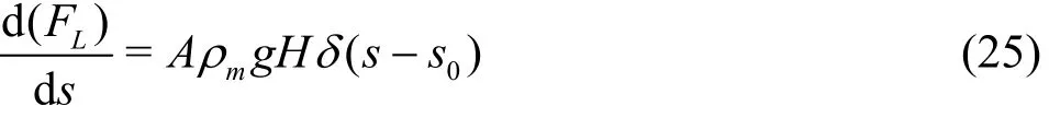
where H is the head of the pump, which refers to the energy transferred to the unit weight of the fluid when it passes through the pump.
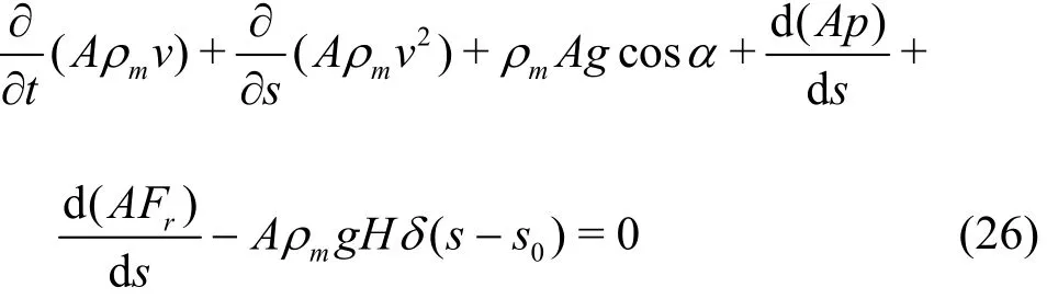
Combining Eq. (24) and Eq. (25), the momentum equation with the pump lift force included can be rewritten as
The pressure changes due to the friction of both the pipe flow and the annulus flow can be calculated as follows[17]:
For the drill pipe
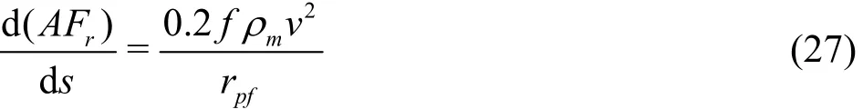
For the annulus
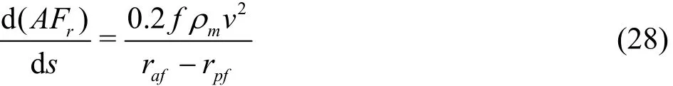
where f is the coefficient of friction resistance.
The coefficient of the friction resistance of both the pipe flow and the annulus flow can be calculated as follows[17]:
For the drill pipe
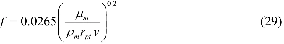
For the annulus
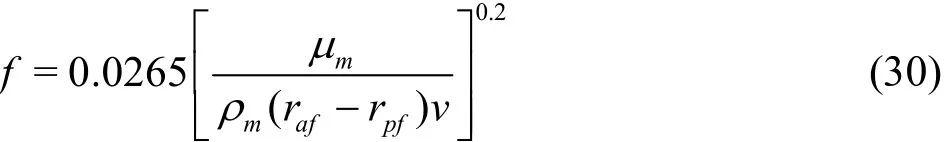
wheremμ is the viscosity of drilling fluid.
2. A coupled solution of temperature and pressure profiles
2.1 Equations discretization
2.1.1 Discretization of the temperature equations
Equation (14) can be rewritten by introducing the unit step function for the convenience of the discretization
where ε(z-z0) is the dimensionless unit step function. The unit step function is the primitive function of the unit impulse function and has the following properties:
The temperature equations of different components are discretized using the first order forward difference scheme.
For the return line
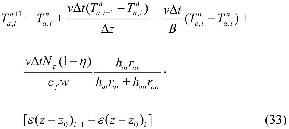
where i-1, i, i+1 is the space node, n, n+1 is the time node.
For the drill pipe in the sea water
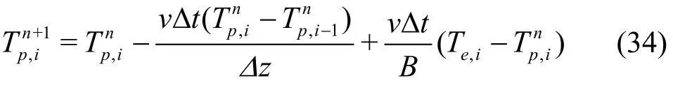
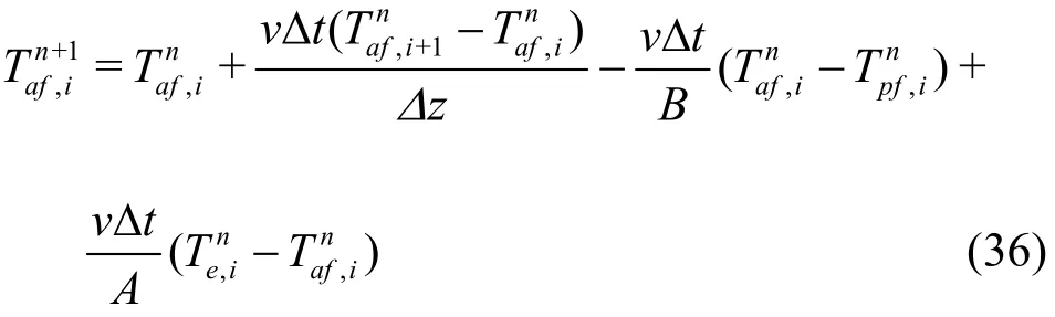
For the drill pipe in the formation
For the annulus in the formation
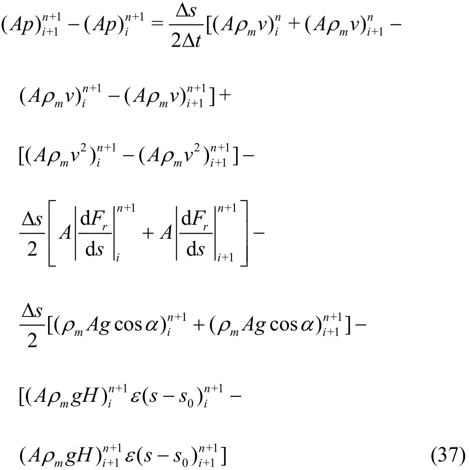
2.1.2 Discretization of the momentum equations
The momentum equation is discretized using the center difference method. Thus
2.2 Drilling fluid density and viscosity related to both temperature and pressure
In the model presented above, the density and the viscosity of the drilling fluid are required in both the temperature and pressure equations. At the same time,they are also affected by both the temperature and the pressure. Therefore, the temperature and the pressure,as well as the density and the viscosity should be dealt with in a coupled manner.
Hoberock et al.[18]developed a fluid density calcula- tion method based on the material balance
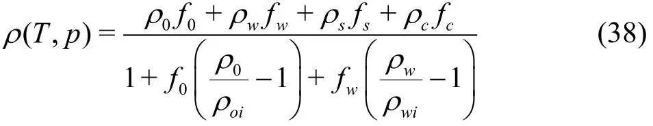
where ρ(T, p) is the drilling fluid density at temperature T and pressure p, f0, fw, fsand fcis the volume fraction of oil, water, solids and chemicals,0ρ,wρ is the oil and water density at original temperature and pressure, ρoi, ρwiis the oil and water density at temperature T and pressure p.
Zhao et al.[19]studied the rheological properties of oil-based drilling fluids at high temperature and high pressure, and proposed the following empirical equation
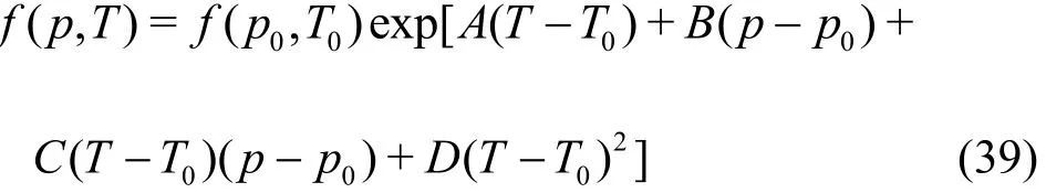
where T0=23.9° C , p0=0 Pa, f(p, T) is the apparent viscosity, plastic viscosity and yield point of drilling fluid.
Combining Eqs. (38) and (39) with the temperature and pressure calculation models presented above, an iterative process of coupling the temperature and pressure solutions can be established.
2.3 Iterative process of coupling the temperature and pressure solutions
(1) The return line, the drill pipe in the sea water as well as the drill pipe and the annulus in the formation are discretized utilizing the one-dimensional Cartesian grid system.
(2) The initial temperature of the system is equal to the environmental temperature, and we have=
(3) The inlet pressure of the subsea pump can be initialized with the hydrostatic head of the sea water:. Calculate the pressure profile using Eq.(37) with consideration of the effect of the initial temperature and pressure on the fluid density and viscosity by Eqs. (38), (39).
(4) For the temperature calculation, the boundary condition of the temperature can be described as follows:
(a) The temperature at the wellhead is equal to the temperature of the drilling fluid on the platform,so that:
(b) The temperature of the wellbore is continuous,so that at the mudline:And at the bottom-hole:
(c) Calculate the temperature at the time step n+1 in the return line, the drill pipe and the annular in the formation as well as the drill pipe in the sea water using Eqs. (33)-(36). The fluid density and viscosity are calculated using the temperature and pressure at the previous time step by Eqs. (38)-(39).
(d) Calculate the pressure at the time step n+1 using the same method as in step (3).
(e) Go back to Step e and continue the iteration until the difference between the solved primary unknowns and those at the previous time step falls within a prescribed tolerance of 0.01 K.
2.4 Model validation
2.4.1 Validation of the pressure calculation model
A comparison is made between the calculated pressures from the model established above and the pressure calculation given by Choe. The basic data[10]of the well are shown in Table 1 and the comparative results are shown in Fig. 2. A promising match against the reported results in literature can be observed.
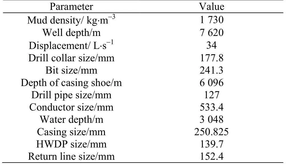
Table 1 Basic data of the well used in the verification model of the pressure calculation
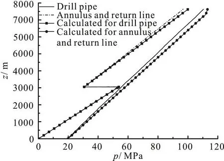
Fig. 2 Comparison results of Choe?s (1998) calculation and our calculations
2.4.2 Verification of the temperature calculation model
Measured temperature data are hard to acquire due to the rare field applications of the DGD system.In order to validate our model, we apply the temperature calculation model to a deep water well drilled using the conventional method. The calculated temperature is then compared to the measured temperature given by Chen and Xie[20], with the basic well data presented in Table 2. The comparisons are shown in Figs. 3, 4. The results generated from the model show a good agreement with the measured field data.
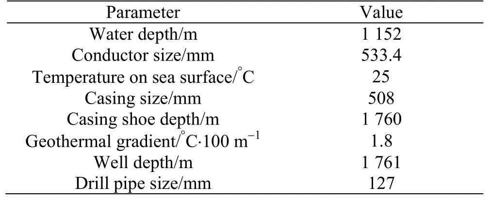
Table 2 Input data used in validation of temperature calculation
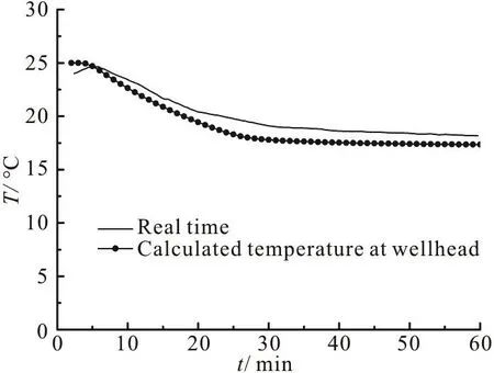
Fig. 3 Real time temperature data at the well head vs. calculated result

Fig. 4 Real time data of the bottom hole temperature vs. calculated result
3. A case study
The developed model is utilized to analyze a deep water well in South Sea. The input data of the simulation well are shown in Table 3.
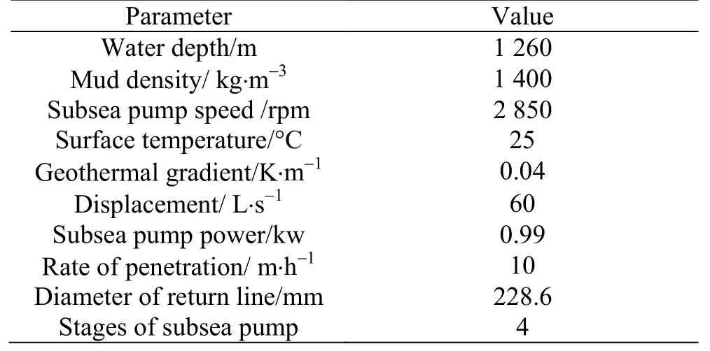
Table 3 Basic data of the simulated well
The casing program of the simulation well is displayed in Fig. 5.
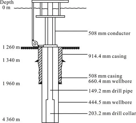
Fig. 5 Casing program of the simulation well
We apply the DGD and the conventional drilling to analyze the case for a comparison. The density of the drilling mud used in the conventional drilling is generally significantly lower than that used in the DGD, and the density of the drilling mud used in the conventional drilling is 1 210 kg/m3in this case.
3.1 Calculated transient temperature using DGD system
The temperature in the wellbore is equal to the environment temperature at the initial time after a long-time period of shutting, and it starts to change and reaches a steady state after restarting the circulation. Figure 6 shows the temperatures at the initial time and in the steady state for the DGD. Variation histories of the temperature at different positions are obtained by numerical calculations, and the results are plotted in Fig. 7.
As shown in Fig. 6, the temperature in the shallow part of the wellbore gets higher after the steady state, while the temperature in the deep part of the wellbore becomes lower. Figure 6 also shows that the temperature of the drill fluid at the mudline for the DGD increases by 1.5°C due to the heat produced by the pump. The drilling fluid of a higher temperature in the deeper part moves upwards and then cools down in the environment, thus the temperature at different positions of the wellbore firstly increases and then decreases with time as shown in Fig. 7.
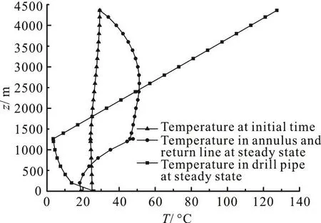
Fig. 6 Temperatures at initial time and in steady state for DGD
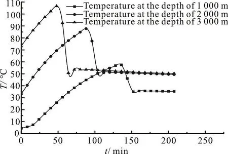
Fig. 7 Transient temperatures varying with time at different positions for DGD
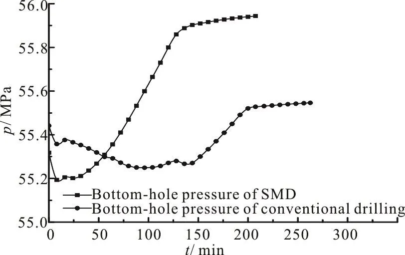
Fig. 8 Bottom-hole pressures varying with time for DGD and conventional drilling
3.2 Comparison of the transient bottom-hole pressure between DGD and conventional drilling
The change of the temperature will have an impact on the density and the viscosity of the drilling fluid. And the pressure will also change accordingly.The key to the DGD process is to precisely control the bottom-hole pressure, thus an analysis of the change of the bottom-hole pressure is made in this paper. The bottom-hole pressure is obtained by the numerical calculation, and the results are plotted in Fig. 8.
As shown in Fig. 7, the temperature at different positions firstly increases and then decreases with time. Accordingly, the density and the viscosity of the drilling fluid will first decrease and then increase with time as indicated by Eqs. (38), (39). The higher density and viscosity of the drilling fluid lead to a higher bottom-hole pressure. As a result, the bottomhole pressure firstly decreases and then increases with time for both the DGD and the conventional drilling as shown in Fig. 8. However, with the conventional drilling, it takes more time to reach the steady state than with the DGD due to the larger volume in the riser as compared to the return line in the DGD.Besides, the difference between the bottom-hole pressure at the initial time and that in the steady state for the DGD is 626 kPa, which is significantly higher than that for the conventional drilling, which reaches 115 kPa. The change of the density and the viscosity of the drilling fluid in the return line has no impact on the bottom-hole pressure due to the constant inlet pressure of the subsea pump in the DGD system. On the other hand, the change of the density and the viscosity of the drilling fluid in the riser does influence the bottom-hole pressure for the conventional drilling, and the temperature in the sea water will become higher after the steady state, as shown in Fig. 6, which is other way round in the deeper part.Consequently, the bottom-hole pressure of the DGD undergoes a greater change from the initial time to the steady state as compared to the conventional drilling.In another word, the bottom-hole pressure is more susceptible to the temperature in the DGD system as compared to the conventional drilling.
In conclusion, the bottom-hole pressure changes greatly as the result of the temperature variation in the DGD system. If the density of the drilling fluid is not appropriate, a kick or leakage of the well will happen as the result of not considering the change of the bottom-hole pressure. Thus, an adequate safety margin is strongly recommended to be considered especially during the design of the hydraulic parameters of the DGD.
3.3 Comparison of the temperature after steady state between DGD and conventional drilling
The calculated results of the temperature after the steady state for the conventional drilling and the DGD are shown in Figs. 9, 10.
3.3.1 The temperature field in the drill pipe in sea water
As shown in Figs. 9, 10, the drill pipe temperature in the sea will slightly decrease with the increase of the water depth for the DGD, which is other way round for the conventional drilling. In the case of the DGD, though the drilling fluid in the drill pipe in the sea is protected by the insulation layer of the conductor, the returned mud of high temperature no longer passes through the annulus of the conductor.As a result, the drilling fluid in the drill pipe loses heat generated by the returned mud of high temperature in the annulus. Thus, the drill pipe temperature in the sea will slightly decrease with the increase of the water depth.
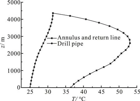
Fig. 9 Calculated temperatures after steady state for conventional drilling with a simulated well
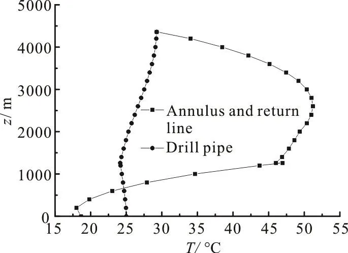
Fig. 10 Calculated temperatures after steady state for the DGD model with a simulated well
3.3.2 The temperature field of the returned drill fluid in sea water
Figure 9 shows that the temperature of the drill fluid at the mudline for the DGD increases by 1.5°C due to the heat produced by the pump. In addition, the returned mud is transported through the return line instead of the annulus of the conductor in the DGD system. Therefore, the drilling fluid in the return line loses the protection of the conductor insulation layer and the temperature in the return line will decrease much more significantly along the flow direction as compared to the conventional drilling.
3.3.3 The temperature field in the drill pipe and annulus in formation
The heat transfer process in the formation for the DGD is the same as the process in the traditional drilling. As a result, the temperature of the DGD in the drill pipe and the annulus in the formation is similar to that of the conventional drilling.
3.4 Comparison of the pressure after steady state between DGD and conventional drilling
The calculated results of the pressure after the steady state for the conventional drilling and the DGD are shown in Figs. 11, 12.
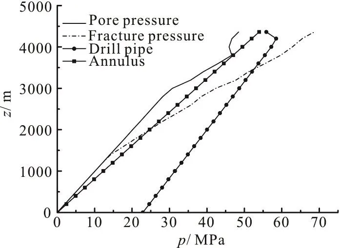
Fig. 11 Calculated pressures after steady state for conventional drilling with a simulated well
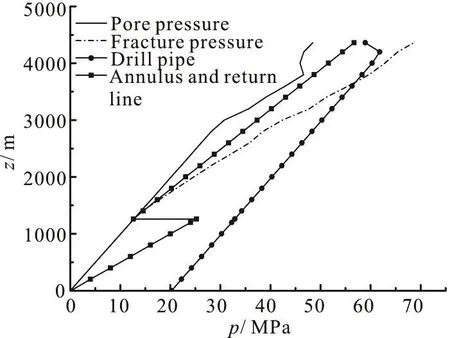
Fig. 12 Calculated pressures after steady state for the DGD with a simulated well
In the case of the conventional drilling, when the density of the drill mud is 1 210 kg/m3, the annulus pressure is equal to the pore pressure (46.13 MPa) at a depth of 3 760 m. Therefore, 1 210 kg/m3is the lowest applicable density of the drilling fluid. However, the annulus pressure (24.2 MPa) is already higher than the fracture pressure (23.9 MPa) at the casing shoe (1 960 m in depth). Thus, the conventional drilling will not be able to drill the open-hole section successfully, and the casing program presented in Fig. 5 is redesigned and shown in Table 4. The result shows that an additional casing string is needed for the conventional drilling as compared to the casing program in the DGD system.
The calculated pressure for the DGD model with a simulated well is shown in Fig. 12. Two types of pressure gradients are generated in the annulus due to the lift force of the subsea pump. In the DGD system,the inlet pressure of the subsea pump is equal to the hydrostatic fluid column pressure of the sea water,which in turn is lower than the hydrostatic fluid column pressure of the drilling mud. Thus the annulus pressure is lower than the fracture pressure at the casing shoe. At the same time, the annulus pressure is higher than the pore pressure due to the heavy drilling mud used in the DGD system. This keeps the annulus pressure between the fracture pressure and the pore pressure, so that the DGD method is successful in drilling the open-hole section. Comparison results between the conventional drilling and the DGD show that the DGD model can simplify the casing program and reduce the number of the casing strings.

Table 4 Resigned casing program for conventional drilling
4. Sensitivity analysis
4.1 Influence of well depth on the transient bottomhole pressure
To study the influence of the well depth on the transient bottom-hole pressure of the DGD, Numerical experiments are performed for different well depths with the same other input data.
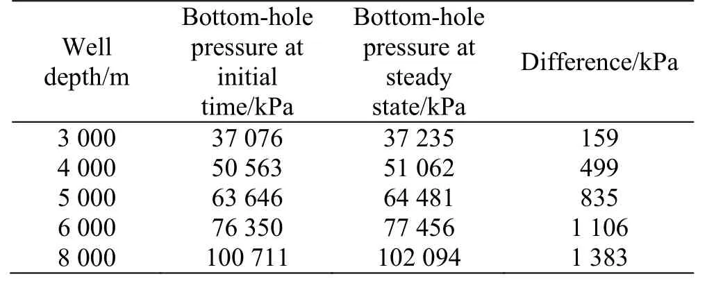
Table 5 Calculated transient bottom-hole pressures of different well depths
The larger the well depth, the higher the environmental temperature will be. Thus, a larger well depth usually means a higher wellbore temperature at the initial time, and the difference between the temperatures at the initial time and in the steady state will be more significant. As a result, the effect of the temperature on the density and the viscosity of the drilling fluid is greater, so is the effect of the bottomhole pressure. As shown in Table 5, the difference between the bottom-hole pressures at the initial time and in the steady state increases with the increase of the well depth. When the well depth is 8 000 m, the difference reaches 1 383 kPa, which is not negligible.
4.2 Influence of geothermal gradient on the transient bottom-hole pressure
To study the influence of the geothermal gradient on the transient bottom-hole pressure of the DGD,numerical experiments are performed for different geothermal gradients with the same other input data.The results are shown in Fig. 13.
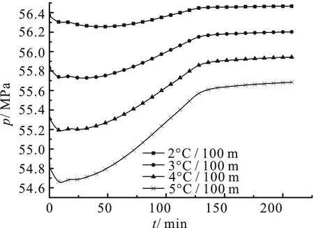
Fig. 13 Bottom-hole pressures varying with time for different geothermal gradients
A higher geothermal gradient leads to a higher temperature in the wellbore, and the density and the viscosity of the drilling fluid will decrease accordingly.Therefore, the wellbore with a higher geothermal gradient usually has a lower bottom-hole pressure, as shown in Fig. 13. In addition, the change of the temperature from the initial time to the steady stage increases with the increase of the geothermal gradient.As a result, the difference between the bottom-hole pressure at the initial time and in the steady state increases with the increase of the geothermal gradient.
4.3 Influence of water depth on the operation range of drilling fluid density
To study the influence of the water depth on the viability of the DGD model, four sets of numerical experiments are performed with different water depths and the same other input data. The operation range of the drilling fluid density (ρrange) can be determined using the model established above. Calculations for different water depths (hsea) are performed using the method to determine the operation range of the drilling fluid density. The comparison results are shown in Fig. 14.
Figure 14 indicates that the operation range of the drilling fluid density in the conventional drilling will decrease with the increase of the water depth.When the water depth reaches 1 094 m, the operation range of the drilling fluid density becomes negative and the open-hole section cannot be drilled successfully using the conventional drilling method. On the other hand, the operation range of the drilling fluid density of the DGD remains stable regardless of the water depth. This observation can be explained by the annulus pressure profile. The DGD annulus pressure is calculated relative to the mudline because of the constant inlet pressure of the subsea pump, which makes the operation range of the drilling fluid density not sensitive to the water depth. However, the annulus pressure of the conventional drilling is calculated relative to the sea surface. Therefore, the operation range of the drilling fluid density decreases as the water depth increases. The results further highlight the advantage of expanding the operation range of the drilling fluid density when drilling in a very deep water using the DGD.
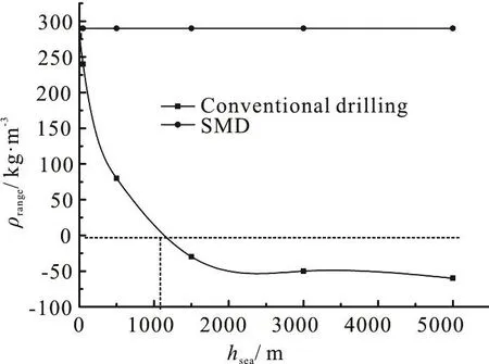
Fig. 14 Operation range of drilling fluid densities for different water depths
5. Conclusions
Combining the specific processes of the DGD systems, a transient temperature calculation model of a wellbore for the DGD is established with consideration of the heat generated by the pump. The momentum equation is modified by considering the lift force of the pump on the drilling mud in the pressure calculation. Besides, an iterative scheme for coupled temperature and pressure calculations is developed. The model is used to analyze a deep-water well in South Sea. The transient temperature and pressure are analyzed through the case study. The major conclusions are as follows:
(1) The temperature and pressure profiles in the DGD have different features as compared to the conventional drilling due to the different flow path and heat transfer in the DGD system. The temperature and pressure calculation method established in this paper can play an important role in the hydraulic parameter design and the overflow prevention.
(2) The bottom-hole pressure changes greatly due to the transient temperature variation, and the change in the DGD system is greater as compared to the conventional drilling due to the constant inlet pressure of the subsea pump. The difference between the bottom-hole pressure at the initial time and in the steady state increases with the increase of the well depth and the geothermal gradient due to the greater change of temperature. With this in mind, an adequate safety margin is strongly recommended to be considered during the hydraulic parameter design of the DGD, especially under the conditions with a deep well depth and a high geothermal gradient.
(3) The operation range of the drilling fluid density for the conventional drilling will be narrowed with the increase of the water depth, and may become negative, which means that the open-hole section cannot be drilled successfully. However, the operation range of the drilling fluid density for the DGD technology can remain stable with the increase of the water depth and the open-hole section can be drilled successfully at any water depth. With the DGD, the safe drilling fluid density range can be enlarged by 340 kg/m3at a water depth of 5 000 m.
猜你喜歡
Chinese Physics B(2022年6期)2022-06-29 08:53:46
奧秘(2022年5期)2022-05-31 02:22:41
中學(xué)生學(xué)習(xí)報(2022年1期)2022-03-21 02:01:29
河北教育(教學(xué)版)(2021年10期)2022-01-14 03:55:30
Chinese Physics B(2021年10期)2021-10-28 07:09:18
邊疆文學(xué)(2020年5期)2020-11-12 02:29:46
書香兩岸(2020年3期)2020-06-29 12:33:45
武大國際法評論(2019年6期)2019-04-09 02:49:52
作文通訊·高中版(2017年6期)2017-07-10 03:21:34
東方教育(2017年2期)2017-04-21 04:46:18

- 水動力學(xué)研究與進展 B輯的其它文章
- Call For Papers The 3rd International Symposium of Cavitation and Multiphase Flow(ISCM 2019)
- Non-invasive image processing method to map the spatiotemporal evolution of solute concentration in two-dimensional porous media *
- Roughness height of submerged vegetation in flow based on spatial structure *
- Large eddy simulation of tip leakage cavitating flow focusing on cavitation-vortex interaction with Cartesian cut-cell mesh method *
- Effects of Froude number and geometry on water entry of a 2-D ellipse *
- Finite element analysis of nitric oxide (NO) transport in system of permeable capillary and tissue *