
Multibody dynamic analysis using a rotation-free shell element with corotational frame
2018-09-05 07:29:16JiabeiShiZhuyongLiuJiazhenHong
Acta Mechanica Sinica 2018年4期
Jiabei Shi·Zhuyong Liu·Jiazhen Hong
Abstract Rotation-free shell formulation is a simple and effective method to model a shell with large deformation.Moreover,it can be compatible with the existing theories of finite element method.However,a rotation-free shell is seldom employed in multibody systems.Using a derivative of rigid body motion,an efficient nonlinear shell model is proposed based on the rotation-free shell element and corotational frame.The bending and membrane strains of the shell have been simplified by isolating deformational displacements from the detailed description of rigid body motion.The consistent stiffness matrix can be obtained easily in this form of shell model.To model the multibody system consisting of the presented shells,joint kinematic constraints including translational and rotational constraints are deduced in the context of geometric nonlinear rotation-free element.A simple node-to-surface contact discretization and penalty method are adopted for contacts between shells.A series of analyses for multibody system dynamics are presented to validate the proposed formulation.Furthermore,the deployment of a large scaled solar array is presented to verify the comprehensive performance of the nonlinear shell model.
Keywords Flexible multibody dynamics·Rotation-free shell·Corotational frame·Geometric nonlinearity
1 Introduction
Space structures or mechanisms are flexible multibody systems,such as flexible solar cells,solar sails and coiled deployable structures.There are three types of formulation for solving flexible multibody system problems based on the choice of the reference frame, floating frame of reference formulation,inertial frame formulation and co-rotational formulation.In general,the floating frame of reference formulation originated from rigid body dynamics and extended to as mall deformation problem.In recent decades,the majority of researchers made use of the inertial frame formulation to solve a great number of problems from the benchmark analysis to the practical engineering applications[1–4].The work of Liu and Liu[5]compared the floating frame of reference formulation and the inertial frame formulation using a hub-beam system experiment.Inertial frame formulation is implemented by popular methods,such as geometrically exact theory,absolute nodal coordinate formulation(ANCF)and isogeometrical analysis.Inertial frame formulation has proven to be very accurate in analyzing the motion of highly flexible structures.It avoids the limitation of small rotation and small strain assumption due to the exact description of strain energy.If the problems are restricted to small strain and finite rotation,the inertial frame method is not as straightforward as co-rotational formulation although the former can be simplified.Co-rotational formulation stems from the concept of isolating the rigid body motion from the overall one in continuum mechanics a half-century ago.The pioneers of the corotational concept are Wempner[6]and Belytschko et al.[7].A lso,Rankin and Brogan[8]proposed an element-independent form of corotational formulation,which makes this method a general and efficient procedure to deal with the large rotation and small strain problems.Recently,Chimakurthi et al.[9]developed a nonlinear structural dynamics solver for flapping-wing using co-rotational and total Lagrangian formulation.In that work,aDKT bending element and OPT membrane element were adopted.Then,Cho et al.[10]also presented a co-rotational approach for geometrically nonlinear structure analysis using quadratic solid-shell element.The work of Faroughi and Eriksson[11]used conventional corotational formulation in analysis of space membranes,and he derived the mass matrix and dynamic tangential stiffness using a current coordinate transformation.
Large-scaled multibody dynamic problems require efficient models.A rotation-free element is a good candidate when dealing with complicated problems,because it avoids the rotational singularity and reduces degrees of freedom.In the finite element method,rotation-free element formulation was developed many years ago.In their work,Sabourin and Brunet[12]made use of a patch of four triangle elements or 4-node elements to calculate the curvature of the center master element.Sabourin’s element is identical to the one developed by Guo et al.[13].Also,O?ate and Cervera[14]and Flores and O?ate[15]used integration by parts of curvatures to derive their plate bending element,and the assumed strain approach was adopted to create the stretching strain.Furthermore,Phaal and Calladine[16]utilized a complete quadratic polynomial in two dimensions to obtain constant curvatures over the whole patch of elements.The work of Zhou and Sze[17]extended Phaal’s element by simplifying the tangent stiffness of bending strain and applied it in geometrically nonlinear problems such as the drape simulation.However,Zhou and Sze[17]used a simplified tangential stiffness matrix to deal with a curved shell,and derived the membrane deformation using total Lagrangian formulation.The corotational formulation was only adopted to handle the bending deformation because the rigid body motion was not derived completely in their approach.
The multibody system consisting of shells are investigated by many authors.To this end,Bauchau et al.[1]proposed a geometrically exact shell for multibody system that incorporates a variety of joints constraints.They used this model in shell buckling analysis and engineering application such as the deployment of solar cell.A lso,Das et al.[18]presented a modified nonlinear shell model combining floating frame of reference and corotational formulation,which makes his shell model capable of solving relative large deformation problems.Liu et al.[19]solved multibody system problem such as the sunfolding process of a satellite system by using absolute nodal coordinate formulation.
The aim of this work is to develop a new rotation-free corotational formulation for large scaled flexible multibody systems without compromising on accuracy.Unlike the element-independent[20]corotational formulation,this work adopted the derivative of rigid body motion to extract the pure deformation. More simple formulas can be achieved instead of using projector matrix[21].Comparing with the previous formulation[17],the presented method adopts the corotational frame to extract both of the bending and membrane deformation, and a complete tangential stiffness matrix is derived for this formulation.
In this paper,a new corotational form of rotation-free element is derived using a detailed description of rigid body motion.Furthermore,the consistent tangential stiffness is given by a full derivative of internal force.To deal with multibody system problems,the joint kinematic constraints and contacts model between shells are deduced in the context of rotation-free shell element. The proposed method is accurate and efficient proved by several numerical examples.Moreover,a complicated system of solar arrays is investigated with large number degrees of freedom,contacts and variable constraints.
2 Corotational form of rotation-free shell
The corotational formulation assumes that the deformation of a shell can be described by the pure deformational displacement,which can be isolated from the overall motion.In other words,the pure deformation can be expressed by overall motion and the rigid body motion.Then the objective strain is obtained by operations on the overall motion and rigid body motion.The isolation of the rigid body motion and the strain calculation are described in this section.
2.1 Corotational kinematics
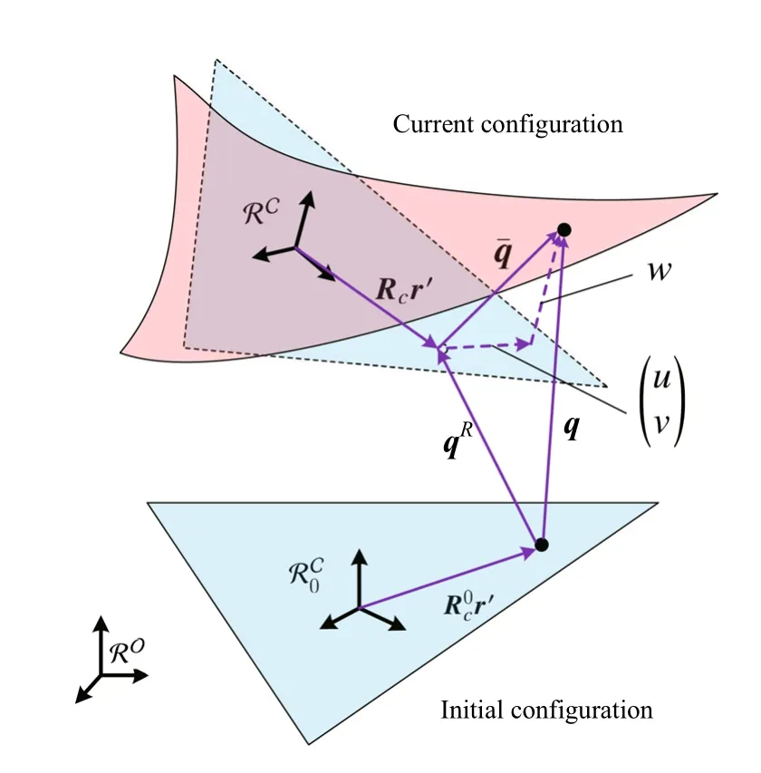
Fig.1 Deformation description

Fig.2 Motion of an arbitrary point on a rigid body
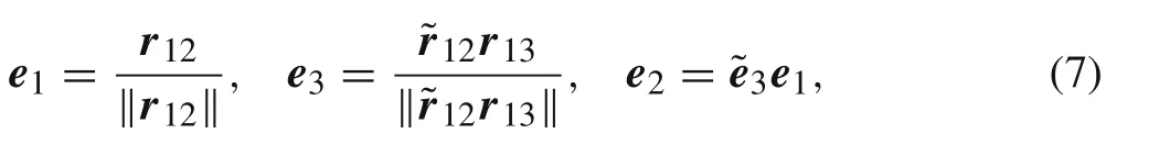
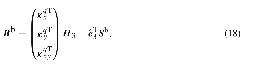
First of all,a simple displacement relation is presented as follows.In Fig.1,the initial plane configuration of a triangle element is denoted by the plane blue triangle and the initial elemental orientation is described by the local frame RC0.The curved red triangle denotes the current configuration of this element whose orientation is defined by the local frame.The direction cosine matrices of frameandareand Rc,respectively.The position of an arbitrary point in the element is r′measured in the local frame,and r′is constant.After an overall motion including rigidbody motion and small strain,q is the overall motion of the arbitrary point.q can be split into rigid body motion qRand pure deformation displacement.The relation can be written as

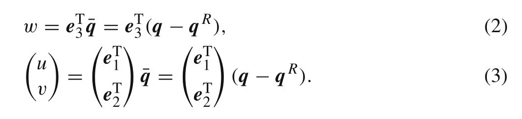
In Eqs.(2)and(3),the rigid body motion qRwill be derived in next section.
2.2 Rigid body motion
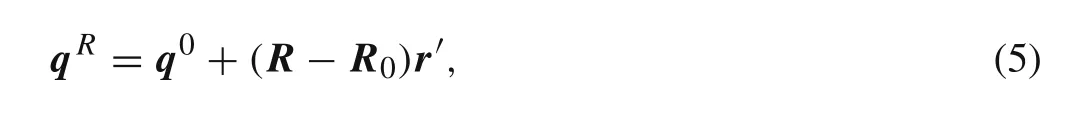
The rigid body motion can be illustrated by a finite rotation and a translation.In Fig.2,the orientation of a rigid body is denoted by R0at initial configuration,and the relative position of an arbitrary point on this rigid body is r0.Assuming that r′is the local position measured in the local frame,r0can be expressed as r0=R0r′.Applying a rigid body motion on this body,the motion of the arbitrary point can be written as

where q0is the translational displacement of the reference point on the body,and qRis the displacement of an arbitrary point on the body.Defining the current orientation as R and r=Rr′leads to
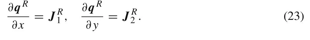
because q0is not related to r′,the derivative of rigid body displacement qRrespect to the local coordinates can be expressed as
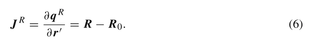
Equation(6)means that the derivative of rigid body motion is the difference of rotation matrices R and R0and which is consistent with continuum mechanics[22].Under the side alignment assumption[23],rotation matrixdefined in a triangle element can be expressed as
where δR0vanishes due to the initial constant orientation.δR can be derived as the way of Nour-Omid and Rankin[20]by using the infinitesimal rotation vectorbut the formulas were deduced under an assumption of the constant element area.An exact result is derived as follows
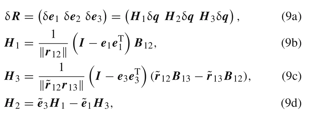
where Bijis the corresponding bool matrix with elements of 0 and 1,and δrij=Bijδq,q is the nodal coordinates of the element.So far the derivative of rigid body motion with respect to the material position is achieved for pure deformation calculation.
2.3 Bending deformation
In their work, Phaal and Calladine [16] developed a linear rotation-free element,which was extended to nonlinear problems by Zhou and Sze [17]. The similar expression can be rewritten as follows. As shown in Fig. 3, the center element’s deflection can be calulated by using the complete quadratic polynomial over the whole element patch as follows


Fig.3 Linear plate bending model for rotation-free formulation
where six coefficients c=(c1,c2,...,c6)Tcan be solved by six deflections w=(w1,w2,...,w6)Tof a patch of four triangle elements as follows
where C is the matrix consists of quantities xiand yiand the ith row of C is.Then the curvature of the center element can be derived easily as
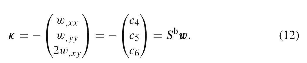
Comparing with Eq.(11),? Sbis the last three rows of C?1.It is obvious that the curvature of the center element is constant.From Eq.(2),the nonlinear curvature expressed by nodal overall displacements can be written as
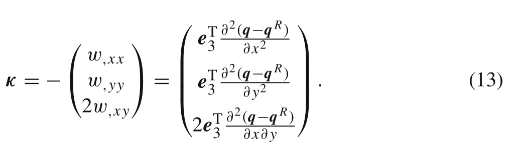
According to Eq.(6),the second-order derivative of rigid body displacements vanish as
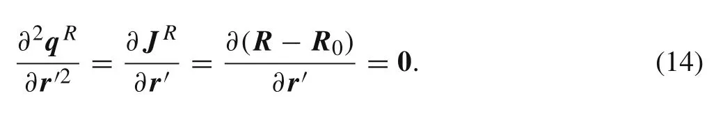
Combining Eq.(13)with Eq.(12),the curvature can be recast as

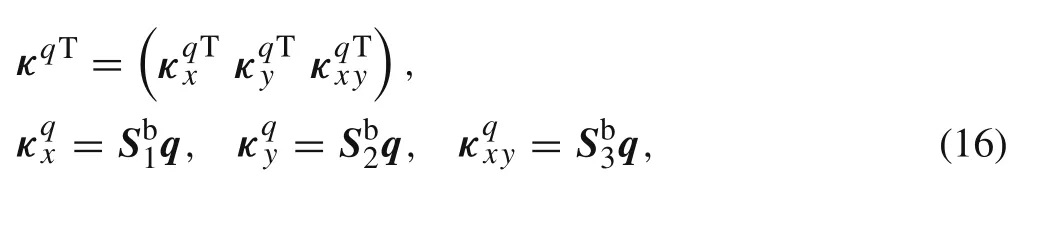

where
which is strain matrix that represents the nonlinear relation between overall displacement and bending strain.
2.4 Membrane deformation
Membrane deformation is derived similar to that of bending deformation,but the derivative of rigid body motion cannot be eliminated.Combining constant strain triangle(CST)and Eq.(3),the membrane deformation can be expressed as

where
The overall displacements can be interpolated by linear shape function as
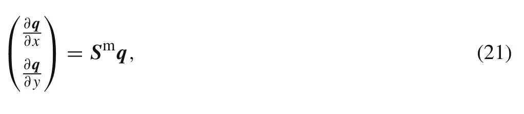
where
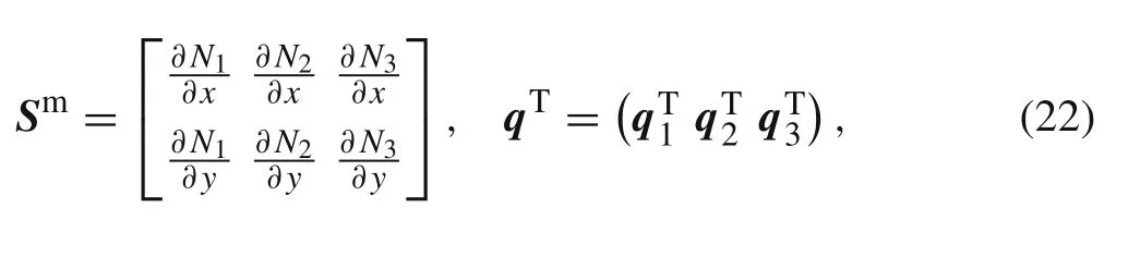
and N1,N2,N3are the area coordinates of triangle elements.The rigid body displacements referred to Eq.(6)can be written as
The membrane strain turns out to be
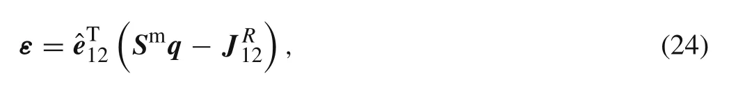

the underlined term vanishes because of the orthogonality of the rotation matrix,and Bmis the strain matrix for membrane deformation.
2.5 Internal force
This work concentrates on problems of large rotation,but small strain,and the linear material constitute is written as

where m andσ are the bending moment and stretching stress,respectively.The material constitute matrices are
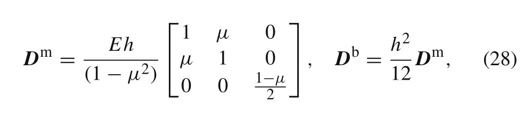
where E is Young’s modulus,μ is Poisson’s ratio and h is the thickness of shell.The elastic energy can be written as
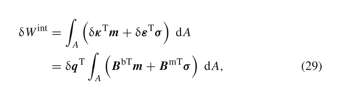
where A is the area of center triangle.From Eqs.(17)and(25),the strain matrix is defined by the nodal variables,which can be isolated from the integration expression.The internal energy can be recast as
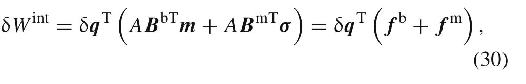
where fband fmare the internal force associated with the bending and membrane,respectively.Differentiating the internal force leads to the tangent stiffness as follows
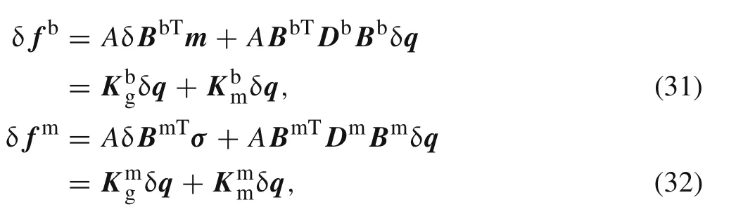
where the first terms of Eqs.(31)and(32)are the geometrical stiffness,and the second terms are the material stiffness.The stiffness matrices are always symmetric which can be used to simplify the formulas.
2.5.1 Linearization of bending
From Eq.(31),the material tangential stiffness matrix is easy to obtain.The geometrical tangential stiffness matrixis derived below.In Eq.(31),δBbTm can be rewritten as
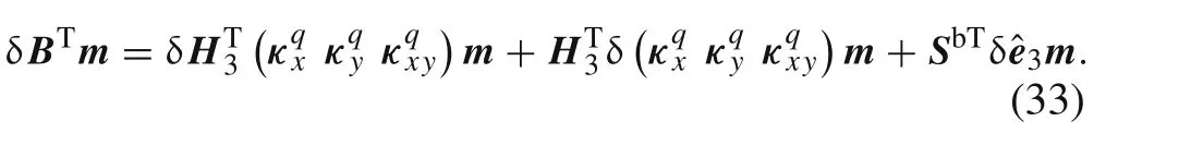
The first term of Eq.(33)can be written as
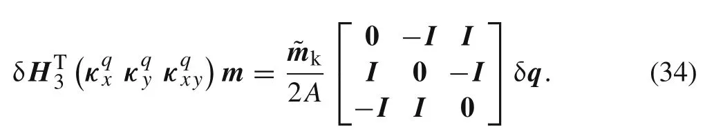
The second term of Eq.(33)can be expressed as
and the third term of Eq.(33)can be proven to be symmetric with Eq.(35).It can be found that the bending stiffness matrix is very easy to achieved and reduce the computational resources.
2.5.2 Linearization of membrane
From Eq.(32),the material tangential stiffness can be simply derived as.The geometrical tangential stiffness can be deduced as below

where the first term can be derived as
and

which is also the transposed matrix of third term.It can be found that the membrane tangential stiffness matrix does not require numerical quadrature over an element and simplifies the computational process.
3 Multibody system with shells
Multibody systems with large number of shells are connected with joints or hinges. The large deformation of shell increases the possibility of contact.Therefore,the constraint and contact models in multibody systems are necessary.
3.1 Joint constraints
Bodies are connected by means of joints and force elements in multibody systems.Ideal joints are described by a joint coordinate system,which is rigidly attached to infinitesimal volume on the flexible body.As shown in Fig.4,elements P and Q of different bodies are connected at point s.A variety of joints can be built by the translational and rotational constraint.Assuming that a translational constraint and a rotational constraint are applied on point s,the joint constraints can be modeled as below.The joint coordinate systems R P and R Q are created on the connected nodes i and k of both bodies using a side-alignment form of local frame.Therefore,the translational constraint can be written as


Fig.4 Joint constraint in multibody systems
The revolute joint would be implemented by adding two rotational constraints.Assuming that n is the revolute axis,two associated unit vectors nPand nQare parallel to n.Applying the transformations nP= RPn′Pand nQ=RQn′Q,the constant vectors n′Pand n′Qcan be obtained in the joint coordinate systems.In R Q,orthogonal unit vectorscan be built.The revolute joint requires vector nQremaining parallel to nP,and two more constraints are implemented by enforcingto remain perpendicular to nP,
A driven constraint can be obtained as follows
3.2 Contact between shells
A node-to-surface contact model with two-pass algorithm is introduced for the proposed shells model.There is no restriction on whether it is a master body or slave body.The contact discretization is shown in Fig.5.The master element surface is surrounded by the three nodes m1,m2,m3.A slave node s contacts with the master surface at the point rm(ξ1,ξ2).ξ1,ξ2is the normalized location or area coordinates in this triangle domain.From Fig.5,the location rmcan be written as
the penetration is denoted by g= ‖rms‖,the normal of the contact surface isand the generalized contact force is as follows
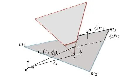
Fig.5 Node-to-surface discretization
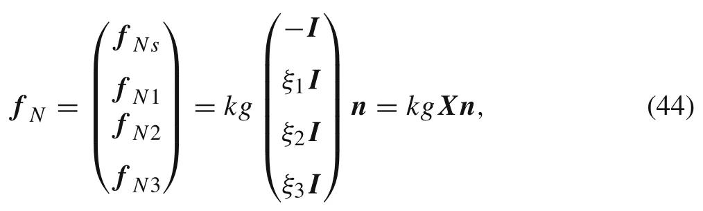
whereξ3=1?ξ1?ξ2,k is the penalty factor that represents the stiffness of contact surface.The larger factor produces more accurate result in physics but poorer computational convergence.The tangent stiffness of contact force is obtained by deriving Eq.(44),

the detailed expressions of the contact stiffness matrices can be found in the contact discretization chapter of the book by W riggers[24].
3.3 Dynamic equations for multibody system


Fig.6 System of three circular strips.a Overall system.b Geometry parameters
4 Numerical examples and applications
To verify the new rotation-free corotational formulation,numerical tests and applications are presented in this section.Multibody dynamic cases can be seen in following subsections and proves that the new formulation is capable of solving complicated problems.
4.1 Unfolding of three circular strips
This multibody problem studied by Das et al.[18]is used to verify the constrained flexible plates undergoing large deformation and rigid body motion.The geometry of this case is shown in Fig.6.The top strip is clamped at one of its ends while the other two strips are connected by revolute joints.The material properties are as follows,ρ=7800 kg/m3,Young’s modulus E=200 GPa,Poisson’s ratio ν=0.3.The driven angle for the revolute joints is defined as follows
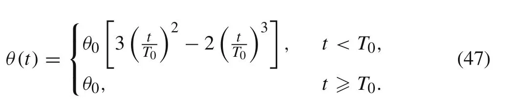
According to Eq.(47),the initial relative angles of three circular strips are zero and at the end of driven time the angles are π.The positions of point A are shown in Fig.7.The positions of point A agree well with Das et al.[18].The configurations and bending energy at certain moment are shown in Fig.8.It can be found that the large rigid motion of circular shells leads to a large bending deformation.
4.2 Cylindrical double pendulum
The case study is presented to show the large deformation coupling with rigid body motion under the action of gravity.This case was studied by Liu et al.[25]using ANCF.The schematics of two segments of semi-cylindrical shell are shown in Fig.9.The diameter of the corresponding cylinder is 0.6 m and the length of segments is 1.2 m.The material parameters are as follows:Young’s modulus of the shell is 1 GPa,the density is7810 kg/m3,the Poisson ratio is0.3 and the thickness is 0.01m.The system is initially horizontal and swings under the external force of gravity.
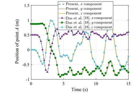
Fig.7 Position of point A

Fig.8 Configurations and bending energy at some instants.a 1.2 s.b 2.5 s.c 6.5 s.d 10 s

Fig.9 Schematics of the two segments of shell.a Isometric views.b The top view(x-z plane view)
The displacement of point A in y direction is shown in Fig.10.The results of two meshes,13×9 nodes and 23×15 nodes,are compared with those of references.Because of using rotation-free elements,the nodal degrees of freedom are fewer than those of ANCF.Although the elements are more than those of the ANCF,the degrees of freedom are almost the same as the reference mesh.The configurations and bending energy of some instants are shown in Fig.11.Because of the simple formulas of the rotation-free corotational method,the computational efficiency is maintained and can be figured out in Table 1.Our solution is obtained using desktop computer with 4 cores CPU and 8 GB memory which shows that much less computational resource is required than that of Ref.[25].
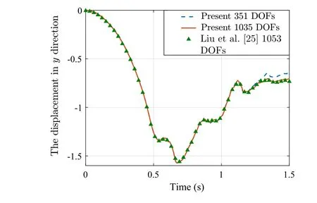
Fig.10 Displacement of point A in y direction
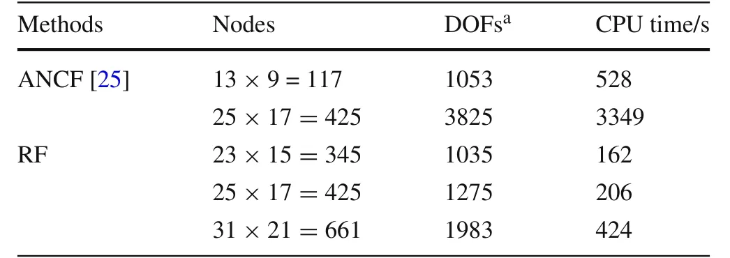
Table1 CPU time of convergent meshes

Fig.11 The configurations and the bending energy of some instants.a 0.2 s.b 0.5 s.c 0.7 s.d 1.0 s
4.3 The draping of a fabric sheet on a sphere
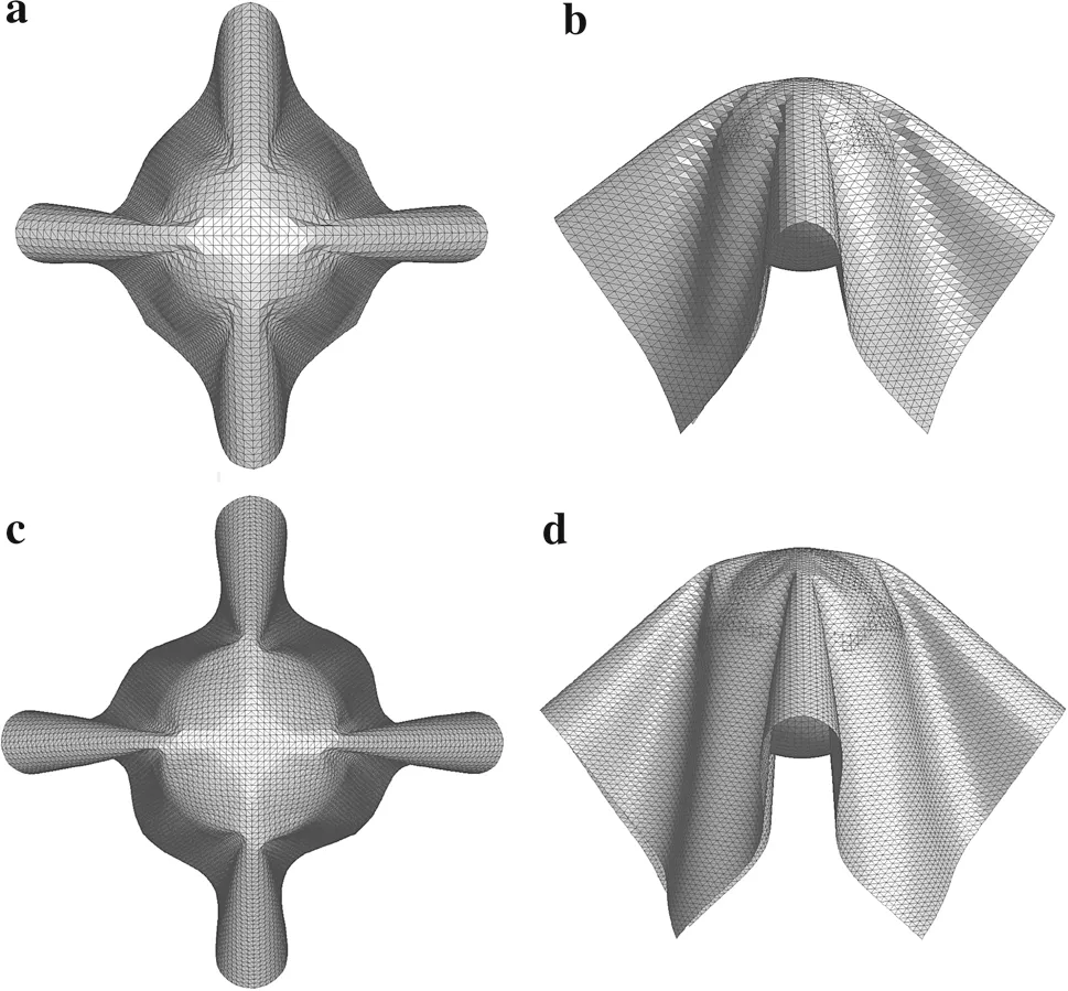
Fig.12 Draping of a fabric sheet on a sphere:the final shape on a top view with 61×61 nodes and b front view with 61×61 nodes,c top view with 101×101 nodes,d front view with 101×101 nodes
This example is studied to validate the rotation-free element in large complex deformation coupling with contacts.The problem is a fabric square sheet0.3m×0.3m with orthotropic material drapes over a rigid sphere?0.1 m found in Refs.[17,26].The material properties are as follows.Tensile rigidities are E1=1095.84 N/m for warp and E2=744.31 N/m for weft,respectively.The shear rigidity is G=40.964N/m.The bending rigidities are F1=8.134μN(yùn)·m2/m for warp and F2=6.174 μN(yùn)·m2/m for weft,respectively.The torsional rigidity for twisting curvature τ=2.646 μN(yùn)·m2/m.The Poisson’s ratio is 0.01,the depth of the sheet is h=0.593 mm,and the density is ρ=320.4 kg/m3.The warps and wefts in the initial configuration are always parallel to the global x and y directions.This drape problem is computed by dynamic relaxation which uses time integration to obtain the steady-state solution.The mass scaling technique is employed by scaling up the mass matrix while the weight remains unchanged.The contact between the fabric sheet and the sphere is considered using the method in Sect.3.2.To maintain the generality of contact detection,the rigid sphere is finely meshed with triangles.
The final shape of the steady-state is shown in Fig.12.The finer mesh(101×101 nodes)leads to a more complete drape configuration than that of the coarse mesh(61×61 nodes)from the wrinkling of the fabric sheet.Figure 13 shows the projections of the final shape in z direction compared with those of Ref.[17].It is worth noting that the projection contour was not given in references, so an approximate contour is obtained by deformed mesh figure in Ref.[17].The presented result with 61×61 nodes shows that the draping contour in z direction agrees well with Ref.[17].The result of fine mesh with 101×101 nodes is a little asymmetric due to the orthotropic material,which also agrees well with those of Ref.[26].This case shows that the presented approach is capable of solving quite large deformation.
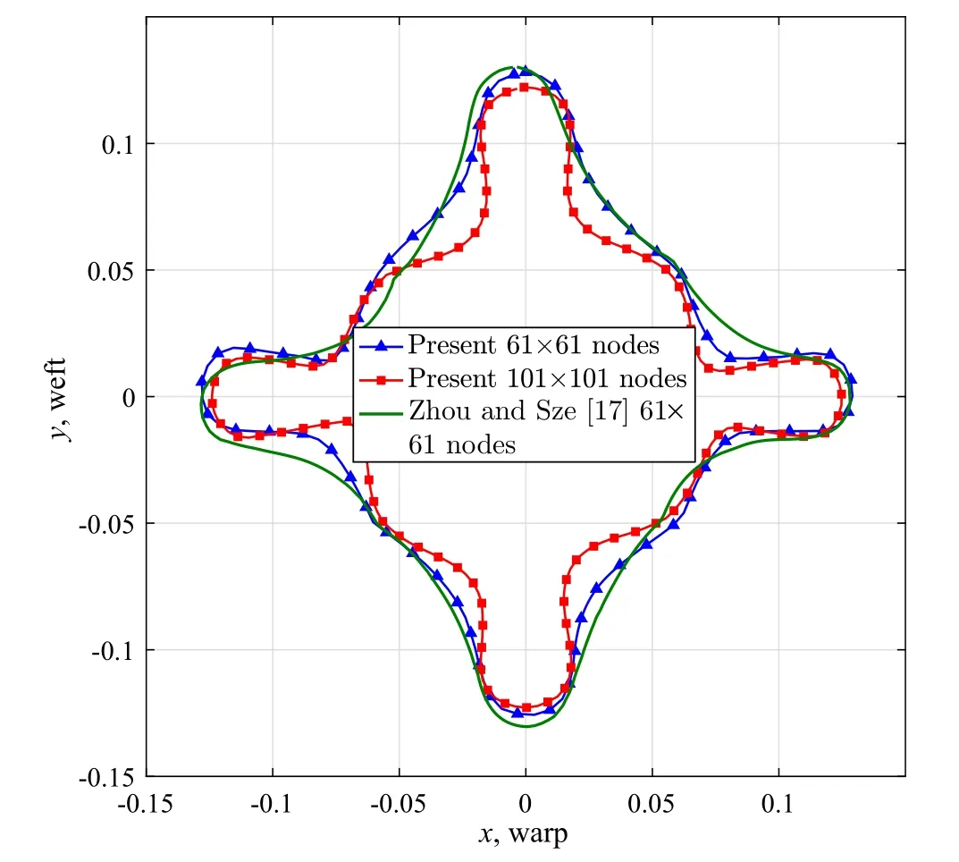
Fig.13 Comparison of projection contour of final shape
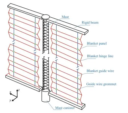
Fig.14 Simplified solar array sketch
4.4 Deployment of solar arrays
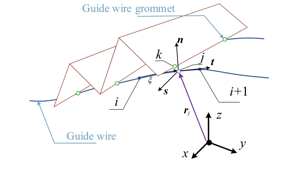
Fig.15 Constraints of sliding on a curve
Solar arrays in space station is complex due to the multiple shapes of structures and mechanisms,such as containment boxes,tensioning mechanisms,the mast and array blankets as shown in Fig.14.The most important part of the solar array system is the blanket panels.They are a series of composite panels that hold the solar cells and are interconnected with hinges to enable the blanket to fold and unfold.Two slightly tensioned guide wires are used for each blanket to assist in deployment and retraction.They run the length of the blanket and interface with the hinges through grommets,but provide negligible out-of-plate stiffness to the blankets after deployment.
In this study,the deployment of solar arrays is modeled and computed using presented approach.The large deformation of blanket panels and the contacts between them are fully considered.Furthermore,the hinge lines of panels slide along the guide wires with the grommets which can be modeled by variable constraints.
A constraint that restricts a point sliding on a curve is shown in Fig.15.Point k slides on a segment of curve defined by means of specific interpolation function with a series of nodes i?1,i,i+1,and i+2.The nearest projection point of point k on the curve segment is point j,which is located at normalized position ξ(0< ξ< 1)of the segment between the nodes i and i+1.The position of point j is denoted by rj,which can be interpolated by the nodal variables(positions and rotations)of the boundary nodes i and j.Furthermore,the tangential vector at projection node can be obtained by t= ?rj/?ξ and two arbitrary orthogonal vectors n and s can be built.Using the definition of point k attached to the curve segment,the constraint can be expressed as

which means that rjkis zero at n and s directions and this constraint restricts the point k sliding along the curve.As for the connection of two adjacent panels,the hinge line is treated as the clamped constraint.
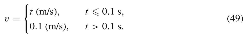
The geometry parameters of each panel are as follows:width W=0.45 m,length L=2.4 m,the thickness h=0.8 mm.The distance between guide wire and the panel boundary is 0.3 m.The material parameters of each panel is that Young’s modulus E=8 GPa,Poisson’s ratio μ =0.3 and the density ρ=2314.8 kg/m3.The diameter of guide wire is 2 mm and its Young’s modulus 210 GPa and Poisson ratio is 0.25.The deployment speed of the mast is applied as follows

Fig.16 Velocities of panels.a First 10 s.b Last 15 s
The top rigid beam is fixed on the mast,and the top row nodes of the 20th panel are attached to the rigid beam.Every panel is meshed with 451 nodes,and the whole degrees of freedom of the blanket panels is 451×20×3=27,060.
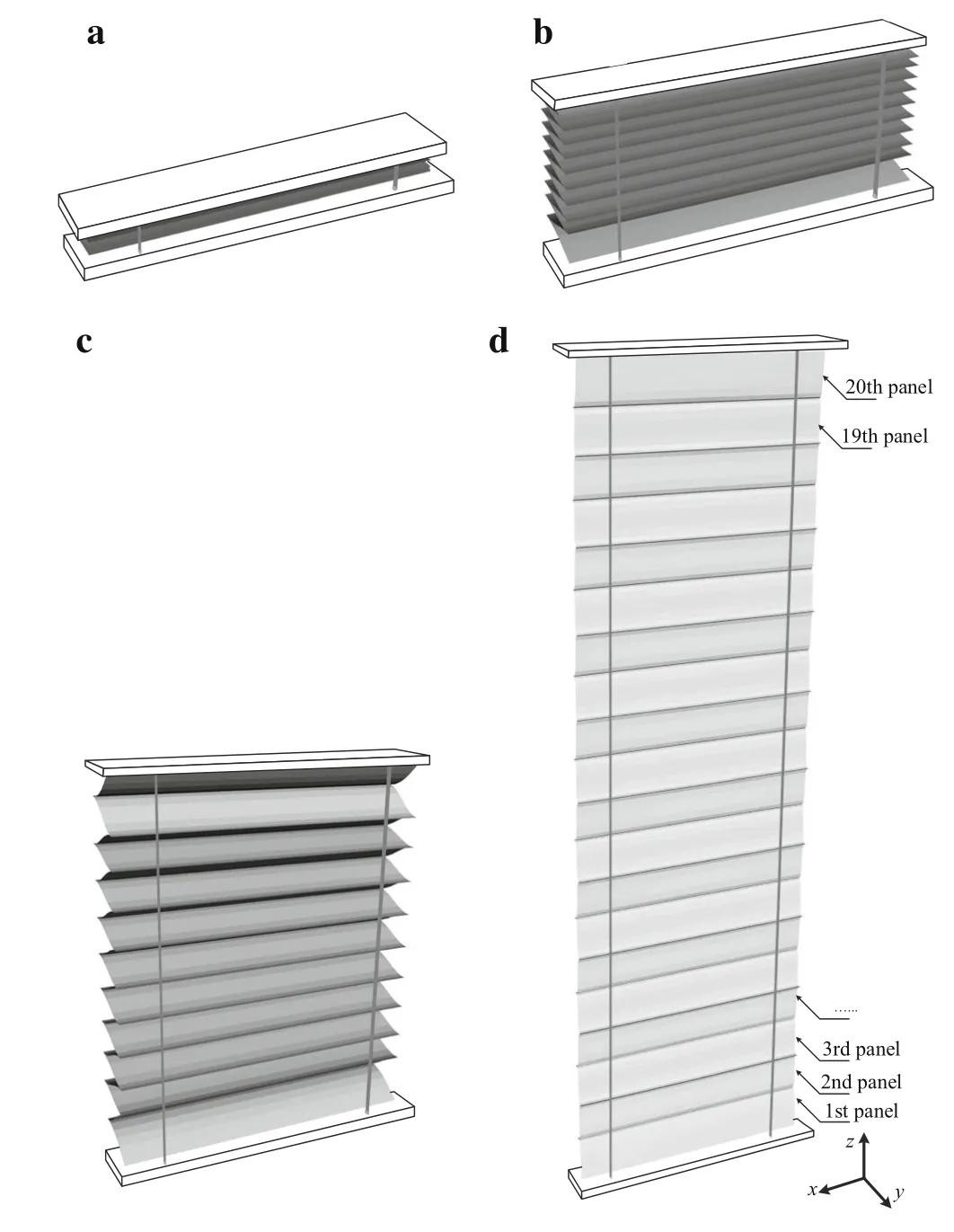
Fig.17 Deployment process of the blanket panels
The blanket panels on one side of the mast are modeled for this computation.The velocities at z direction are shown in Fig.16.At the beginning of the deployment,the velocity responses of panels jump intensely due to the initially contact between folded panels.The velocity of drive point is gradually stable at 0.1 m/s until the end of simulation.The velocity peaks appear in the order of plate numbers.At the end of the deployment,the frequencies of the panels increase since the tension force grows gradually.Because the length of whole configuration is quite different from that at the beginning,the corresponding magnitude of the velocities become larger.Thus,it can be found that the frequency characteristic is influenced by the tension force and the system’s vibration nature would change in the deployment process.The deployment process is shown in Fig.17.The panels are initially folded as shown in Fig.17a.Once the rigid beam rises under the driver mast,folded panels are in contact with each other,which happens in Fig.17b.At the middle and end of the deployment,the panels are tensioned and show large deformations and displacements as demonstrated in Fig.17c,d.Because of the flexible guide wires,the grommets in lateral direction can be measured as shown in Fig.18.It can be found that the initial contacts affect the displacements very much.On the other hand,the initial contacts phenomenon requires more consideration in design.
5 Conclusion
A corotational rotation-free shells formulation is proposed for multibody system analysis.Numerical simulations of multibody system are presented,and a complicated deployment of solar array is simulated for engineering purpose.
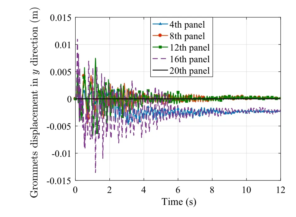
Fig.18 Grommet displacement in y direction in first 12 s
The new proposed rotation-free shell formulation uses the corotational frame to isolate the rigid body motion from the overall motion.Instead of the conventional corotational formulation that adopts projector matrix to extract the pure deformation,the presented approach utilizes a derivative of rigid body displacements to obtain the deformational displacements.The internal force is simply obtained by the classic finite element process,and corresponding tangent stiffness matrices are derived.To handle the multibody dynamic problems,joint kinematic constraints and contacts between shells are deduced in the context of presented shell model.Multibody applications including constraints and contacts are investigated to prove that the proposed method is accurate and efficient.The deployment of a largescaled solar array is simulated considering large deformations,contacts and complex constraint conditions,and the obtained results could help engineers in designing of complicated space stations.
AcknowledgementsThis research was supported by the National Natural Science Foundation of China(Grants 11772188,11132007).

- Acta Mechanica Sinica的其它文章
- A frequency-domain method for solving linear time delay systems with constant coefficients
- Review of deployment technology for tethered satellite systems
- An improved dynamic model for a silicone material beam with large deformation
- Isogeometric analysis of free-form Timoshenko curved beams including the nonlinear effects of large deformations
- Reducing the anisotropy of a Brazilian disc generated in a bonded-particle model
- Numerical computation of central crack growth in an active particle of electrodes influenced by multiple factors