
Numerical modelling of supercritical flow in circular conduit bends using SPH method*
2017-04-26 06:01:28NikolaRosiMilenaKolareviLjubodragSaviDejanaoreviRadomirKapor
水動力學(xué)研究與進(jìn)展 B輯 2017年2期
Nikola M. Rosi?, Milena B. Kolarevi?, Ljubodrag M. Savi?, Dejana M. ?or?evi?, Radomir S. Kapor
1.Faculty of Civil Engineering, University of Belgrade, Belgrade, Serbia, E-mail:nrosic@grf.bg.ac.rs
2.Energoprojekt-Hidroinzenjering, Belgrade, Serbia
Numerical modelling of supercritical flow in circular conduit bends using SPH method*
Nikola M. Rosi?1, Milena B. Kolarevi?2, Ljubodrag M. Savi?1, Dejana M. ?or?evi?1, Radomir S. Kapor1
1.Faculty of Civil Engineering, University of Belgrade, Belgrade, Serbia, E-mail:nrosic@grf.bg.ac.rs
2.Energoprojekt-Hidroinzenjering, Belgrade, Serbia
The capability of the smoothed-particle hydrodynamics (SPH) method to model supercritical flow in circular pipe bends is considered. The standard SPH method, which makes use of dynamic boundary particles (DBP), is supplemented with the original algorithm for the treatment of open boundaries. The method is assessed through a comparison with measured free-surface profiles in a pipe bend, and already proposed regression curves for estimation of the flow-type in a pipe bend. The sensitivity of the model to different parameters is also evaluated. It is shown that an adequate choice of the artificial viscosity coefficient and the initial particle spacing can lead to correct presentation of the flow-type in a bend. Due to easiness of its implementation, the SPH method can be efficiently used in the design of circular conduits with supercritical flow in a bend, such as tunnel spillways, and bottom outlets of dams, or storm sewers.
Smoothed-particle hydrodynamics (SPH), super critical bend flow, helical flow, artificial viscosity
Introduction
The smoothed-particle hydrodynamics (SPH) is the most popular meshfree particle method for fluid flow simulations. Although it was initially developed and used for astrophysical computations[1], nowadays, it is gaining increasing popularity in solving different engineering problems. A range of possible engineering applications can be found in Refs.[2-4]. Capabilities to model free-surface and non-Newtonian flows that are described with complex rheological models are the main advantages of SPH over Eulerian, grid-based methods in solving hydraulic engineering problems. The fact that it does not require free surface tracking and gridding techniques, makes it attractive for modelling these flows. As a meshfree method, the SPH is especially suitable for the simulation of discontinuous free-surface flows, where free surface tracking and gridding are challenging tasks for grid-based methods. Since the numerical solution is sought for moving particles, the SPH method is computationally very demanding when compared with grid-based methods. However, recent development of parallel computing techniques enabled faster computations and wider application of the method in solving engineering problems[5].
A supercritical flow in a closed conduit bend is a good example for testing capabilities of the SPH method in solving hydraulic engineering problems. Thesupercritical bend flow may develop in tunnel spillways and bottom outlets of dams, in storm sewers and in diversion tunnels. Due to high uncertainty about flow conditions that might develop therein, bends are commonly avoided, even at the expense of an increase in the construction costs.
The supercritical flow in a bend causes abrupt depth and velocity disturbances that spread further downstream (Fig.1). A positive standing wave develops along the outer wall, and a negative wave develops along the inner wall. In the case of a significant disturbance, the positive wave reaches the conduit invert and flow becomes helical (Fig.2(a)), or, for even larger disturbances, the flow turns to a choking flow (Fig.2(b)).
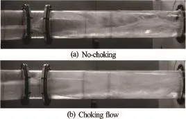
Fig.2 Helical and choking flow in the pipe bend
The choking flow must be avoided, due to its periodicity, which is characterized by successive changes from pressurized to free-surface flow, and the entrainment of large amount of air into flowing water. This reduces conduit capacity and provokes vibrations. Even though no-choking helical flow may be permissible, it should be avoided for the design flow in order to stay on the safe side.
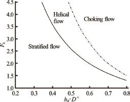
Fig.3 An example of limit curves for onset of helical and choking flow[6]
Previous experimental studies[6,7]have shown that the flow-type in the pipe bend depends on the deflection angle, bend curvatureand the flow characteristics upstream of the bend (i.e., the relative depth, and Froude numberMoreover, relationships which predict conditions for the development of the helical and choking flows were defined (Fig.3).
This paper aims at estimating a capability of the SPH method to predict the flow-type in the circular pipe bend. An open source code DualSPHysics[5,8,9]is modified for the purpose of modelling supercritical flow in circular pipe bends. The code is supplemented with an original algorithm which provides correct interpretation of the upstream boundary condition. The modified code is tested and verified against the experimental data.
The SPH method is applied to the so-called “clear”water flow, i.e., the flow with no air entrained. Since the significant entrainment of air can be expected only after the flow becomes helical, it seems appropriate to use the one-phase flow assumption to estimate the inception of the helical flow. With this assumption computations are markedly less demanding.
One experimental dataset[6]is used for model calibration, and another one[6,7]for its verification. Special attention is paid to the sensitivity analysis, in which the quality of the model performance is assessed by varying artificial viscosity coefficient and initial particle spacing.
1. Numerical model
The DualSPHysics code based on the standard SPH method is used in this study. This version of the SPHysics code is developed for GPU computations. A more detailed explanation of this code can be found in Refs.[5,8,9].
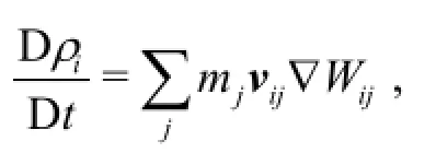
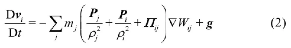
As it is already known the SPH method uses a set of particles to present a moving fluid. Hence, the SPH method solves equations of fluid dynamics that are written using material derivatives. The method applied in this study solves the continuity and the momentum equations in this form
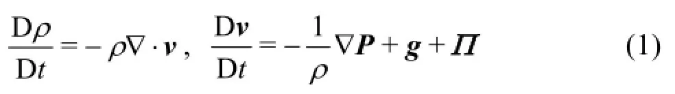
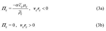
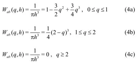
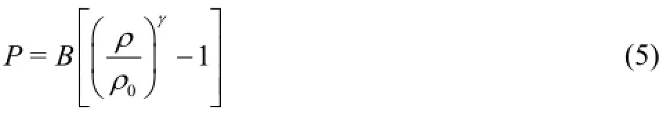
In the standard SPH method, the fluid is treated as weakly compressible, and the pressure is calculated from the equation of state. This approach is computationally less demanding than the incompressible fluid model, where Poisson equation has to be solved. The following equation of state (Tait’s equation) is used
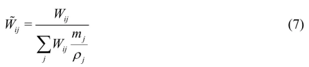
The SPH simulations with the presented equations are followed by pressure oscillations. To avoid this spurious effect the following correction, so-called“smoothing of density” may be periodically applied
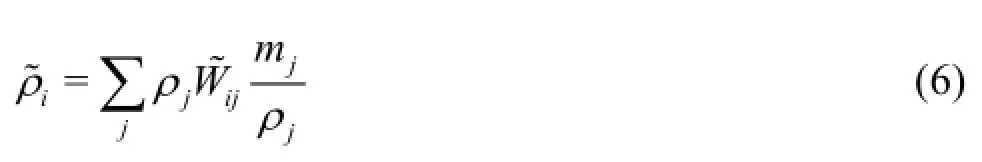
This formulation is known as Shepard’s filter[11]. The kernel weighting function is corrected as follows
In this study, the filtering was repeated after 35 steps. Results have shown, that smoothing of the density (pressure) field can stabilise computation in the absence of the artificial viscosity term.
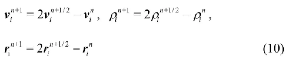
Time integration of Eqs.(2) was performed using a predictor-corrector scheme that consists of three steps. The predictor valuesin the first step, are calculated according to:
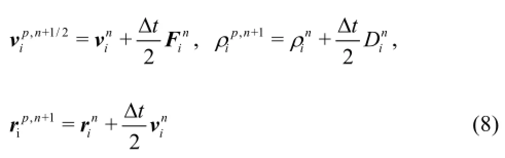
These values are then corrected in the corrector step:
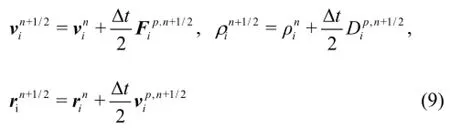
Final values at the end of the time step are calculated in the last computational step, as follows:
The mechanical energy loss coefficient in the pipe bend was calculated using Bernoulli’s equation for compressible flow
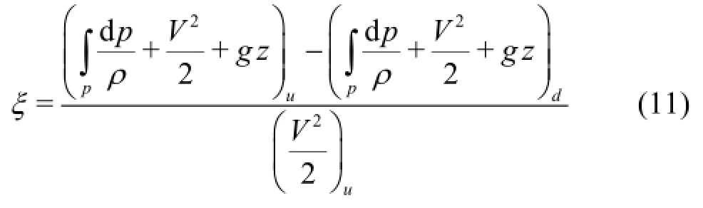
Terms in the equation are time averages, and subscriptsdenote the upstream and downstream crosssections respectively.
In the version of the SPH method applied in this study, a pipe wall is modelled using the?so-called?dynamic boundary particles (DBPs)[12]. These particles remain still (their position is fixed) during the computation. However, they appear in relationships for the approximation to the derivatives of the fluid particles that are located within the distance offrom the boundary. For DBPs, the density is computed from the continuity equation, and the pressure change is computed from the equation of state. When a fluid particle approaches the wall particles (DBPs), the pressure increases, thus creating a repulsing mechanism that prevents the fluid from penetrating through the solid boundary.
In the case of a supercritical flow, boundary conditions must be prescribed at the upstream end of the computational domain. The treatment of an inflow/ outflow boundary with the SPH method is still not satisfactorily resolved. For instance, Federico et al.[13]proposed a technique based on fixed ghost particles[14,15]for solving this problem. However, the use of fixed ghost particles is not as simple as that of DPBs. Moreover, particles in the buffer zone, from which they enter the physical domain considered are constantly generated by additional algorithm, which makes the whole computational procedure cumbersome, and thus not suitable for parallelization using GPUs.
Since the steady state is reached fairly fast in the problem under investigation (in just a few seconds), it is more efficient to load all particles in the buffer zone in front of the upstream boundary at the beginning of computation (i.e., no new particles are generated during the computation). Hence, a new procedure is developed in this study. Particles in the buffer zone form a water column with prescribed velocity and pressure. The column is translated through the upstream boundary into the flow domain. As with the Federico et al., there is no influence of particles from the considered flow domain on particles in the buffer zone (while the buffer zone particles influence those in the flow domain). This basically means that only a position of the buffer particle is calculated from the given velocity value. Consequently, the computational time is rather independent of the number of particles in the buffer zone. Furthermore, the authors suggest that the water column in the buffer zone is positioned such that the distance from boundary particleson the inflow boundary is greater thanas illustrated on Fig.4. This distanceaffects the pressure difference between the DBP at the inflow boundary and the fluid particle that enters the flow domain and, consequently, the repulsion between the two particles, which may provoke numerical instability.
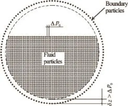
Fig.4 Cross-section beyond real upstream boundary of the physical domain
Repulsion problems might arise due to the fact that DBPs have no influence on buffer particles, which start to approach the solid boundary as they enter the flow domain, thus provoking a greater increase of pressure in DBPs than that developed when the flow domain is already populated with particles. To estimate the pressure rise in the DBP, a movement of an arbitrary, single fluid particle towards the solid boundary is analyzed. The change of pressure in DBPs may be calculated from expressions (2) and (5) using the following relation
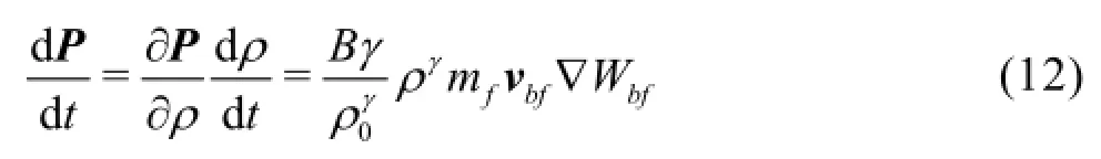
The relation shows that the change in pressure for the given flow velocity depends on compression parameters of the fluid on one side, and the particle spacing, via gradient of the weighting function, on the other side. Authors suggest an increase in distance of the buffer zone from the boundaryas a solution to the problem of the pressure discontinuity, since compression parameters are overall constants. The increase in distance means that the gradient of the weighting function is reduced. The weighting function is a monotonously decreasing function within the interval. Figure 5 shows the particle distribution for three distinct values of. Boundary particles (DBPs) are set at the bottom, below fluid particles of the flow domain. In these examples the particle velocity is 2 m/s, the water column height is 0.05 m and the initial particle spacing is
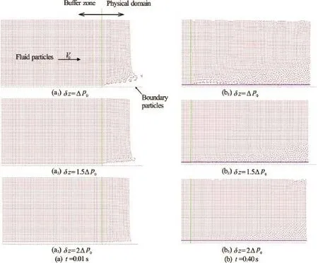
Fig.5 (Color online) Influence ofon the flow pattern
Figures 5(a1)-5(a3) undoubtedly confirm that the increase in the buffer zone distanceresults in reduced bouncing of fluid particles from the boundary (whenthere are no bounced particles, Fig.5(a3)). Distributions of particles 0 s, 40 s after the beginning of simulation (Figs.5(b1)-5(b3) show that the distance at which fluid particles are kept away from DBPs is approximately(horizontal line) in either case. It is also interesting to take a look at the particle distribution near the free surface. It is readily noticeable that there is no disturbance of the free surface only when, and that notable disturbances are developed when. In the case whendisturbances are small. Therefore, the choice of the optimal value offor arbitrary flow geometries is left for further investigation. For all simulations in this study (circular pipe bend) initial distance is, since oscillations of the depth and the velocity are negligible.
2. Experimental setup
The study of the supercritical flow in a pipe bend with the SPH method described in the previous section is based on the experimental results of Kolarevi? et al.[6]. The experimental setup consists of the upstream reservoir, followed by a 0.45 m long transitional section and a horizontal 0.15 m diameter pipe (Fig.6). The circular pipe is made of 2 m long upstream, and 1.5 m long downstream, straight sections with the circular bend in between.
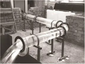
Fig.6 Experimental setup
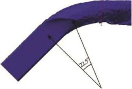
Fig.7 (Color online) Location of the cross-section where the wave reaches the pipe invert ()
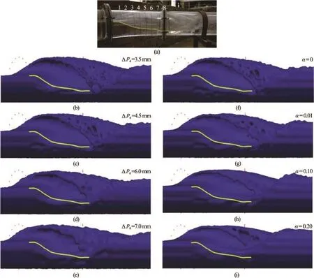
Fig.8 (Color online) (a) Helical flow in the pipe bend in the experiment[6], (b)-(e) influence of) on the flow in the pipe bend, (f)-(i) influence ofα(for)
Kolarevi? et al.[6]performed a series of experiments to study the influence of the deflection angle and bend curvature on the type of the bend flow. In this paper the bend curvature ofand the deflection angle ofare considered.
3. Numerical simulations
To enable comparison between numerical and physical model results, it is necessary to provide the same values of the flow discharge and the depth at the gauging location. Since the described method for the definition of the upstream boundary condition requires shifting of the fluid particles from the solid boundary, the flow depth cannot be assigned at the gauging section, but some distance upstream. Hence, the depth of the water column at the fictitious upstream boundary must be determined by a trial and error.
Courant number value of 0.3 and the sound celerity of approximately 30 m/s are used in all numerical simulations to provide a stable computation and to prevent fluid particle penetrating through the solid boundary. The initial particle spacing is varied in the range between 3.5 mm and 7.0 mm. In addition to the particle spacing, the most important parameter in these simulations proved to be the artificial viscosity coefficient(Eq.(3)).
The open source code DualSPHysics is modified to enable inclusion of the open boundary condition. This requires that all particles are loaded into GPU memory at the beginning of computation. Initially, the pipe is empty, and particles form the water column upstream of the boundary (buffer zone). The length of the water column (i.e., the number of particles) is determined from the simulation time necessary to reach the steady state. The maximum number of particles was approximately 8×10⁶, which resulted in a GPU time of 8 hours that was necessary to simulate 10 s on GTX 970 GPU.
4. Results
The numerical model is calibrated against the experimental data from the scenario with helical flow.The flow discharge in this experiment was 22.4 l/s and the flow depth was 0.09 m. The calibration criterion is a requirement to match the location of the section where the positive standing wave reaches the pipe invert in the experiment. The wave reached the pipe invert in the physical model in the cross-section with, measured from the beginning of the bend (Fig.7). The best agreement between the two models (numerical and physical) is achieved with no artificial viscosity. It should be noted that in the absence of the artificial viscosity, the Shepard filter is required for stable computation. As it was expected, a better agreement with the measurements is attained with lower values of, with the remark that no significant improvements are achieved for
Simulated water surface profiles for differentandvalues are compared to the measured one in Figs.8(a)-8(i). The measured water surface profile along the inner bend is presented with the line. It is readily noticeable that the increase in bothαanddeteriorates the agreement with measurements, i.e. that the best agreement is accomplished with no artificial viscosity addedand smallvalue. The normalized RMS errors CV (RMSE) in cross-sections 1 to 8 (Figs.8(b)-8(i)) for the analyzedvalues are presented in Tables 1 and 2, respectively. The error is calculated from the following expression
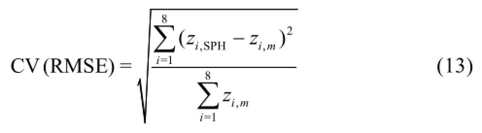
Table 1 Normalized RMS errors CV(RMSE) in cross-sections 1 to 8 for the analyzedvalues and
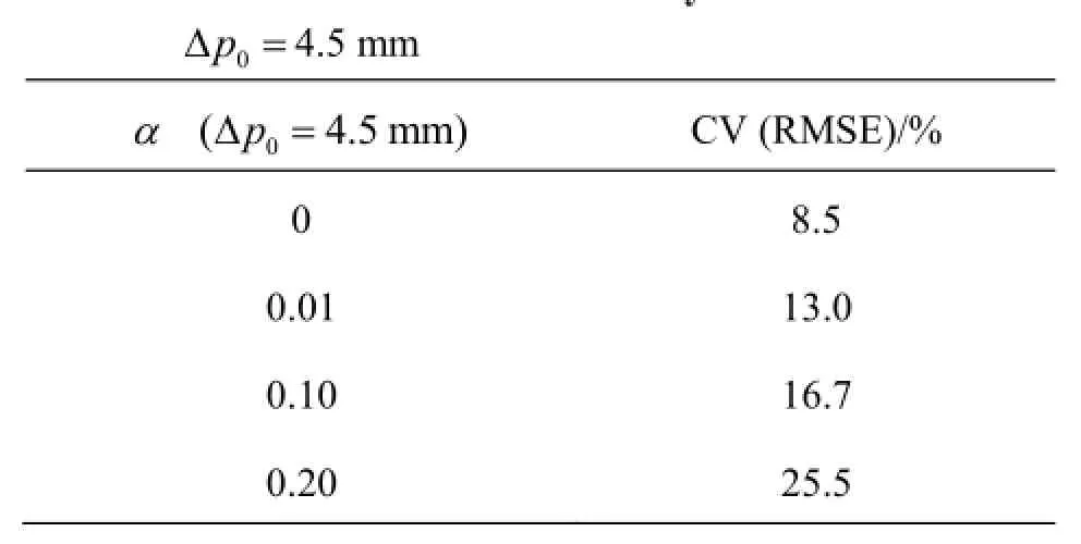
Table 1 Normalized RMS errors CV(RMSE) in cross-sections 1 to 8 for the analyzedvalues and
?
Table 2 Normalized RMS errors CV (RMSE) in cross-sections 1 to 8 for the analyzedvalues and no artificial viscosity added
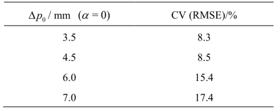
Table 2 Normalized RMS errors CV (RMSE) in cross-sections 1 to 8 for the analyzedvalues and no artificial viscosity added
The sensitivity of the location where the wave reaches the pipe invert, i.e. the sensitivity of the invert anglevalue is presented in Fig.9. It is evident that theangle is rather insensitive to the change invalue. The sensitivity of the invert angleto the initial particle spacingis presented in Fig.10. One can notice that the agreement between the computed and measured values is better for lower values of
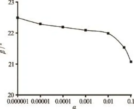
Fig.9 The influence of the artificial viscosity coefficienton the invert angle
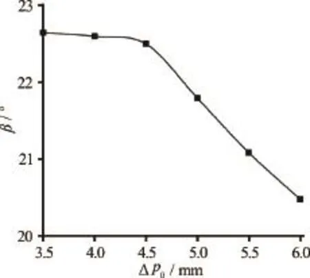
Fig.10 The influence of the initial particle spacing, on the invert angle
The influence of the two parameters on the bend loss coefficientis presented in Figs.11 and 12. It is obvious that the bend loss coefficient increases withan increase in both artificial viscosity (Fig.11) and the particle spacing(Fig.12). Additionally, there is an abrupt increase in
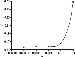
Fig.11 The influence of the artificial viscosity coefficienton the bend loss coefficient
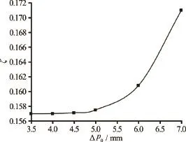
Fig.12 The influence of the initial particle spacingon the bend loss coefficient
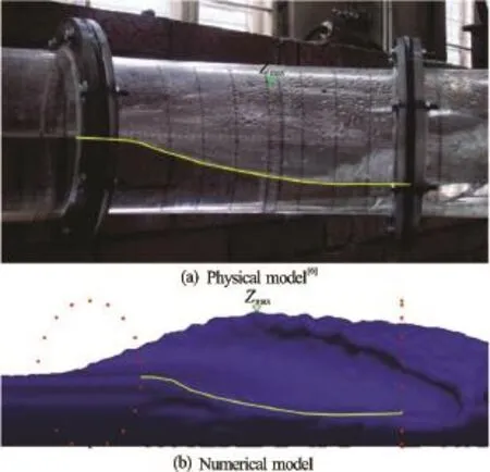
Fig.13 (Color online) Flow without turning (and4.5 mm)
The model is verified against the data from the scenario in which the flow had not yet become helical (Fig.13). The photograph of no-turning flow in the experiment is given in Fig.13(a), while the numerical simulation results are presented in Fig.13(b). The agreement between numerical and experimental results in the bend is even better than in the case with the helical flow (the corresponding CV (RMSE) is 6.1%, when compared with 8.5% for helical flow, Table 1). Moreover, the simulated and observed maximum depths on the outer bend are almost identical. Since the air-water flow is not modeled in this study, better prediction for the case without turning of the flow, where less air was entrained than for the case with the helical flow, would be expected.
To assess the capability of the SPH method to predict conditions for the establishment of the helical flow in the pipe bend, scenarios with various values of the relative flow depth and Froude number are simulated, using parameters defined in the calibration process (i.e., for). These simulations may be understood as additional model verification. Numerical simulation results are presented in Fig.14 together with the limit curves for the onset of helical flow, based on experiments of Kolarevi? et al.[6], Hager and Gisonni[7]. Both limit curves are regression curves derived from the experimental data.
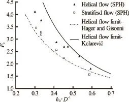
Fig.14 Comparison between numerical and experimental results
Since numerical simulation results lie midway between the two curves in the whole range of relative inflow depths and Froude numbers, the authors do believe that the SPH method results can be used as a good estimate for the preliminary design of closed conduits with bends in the case of supercritical flow, when the physical model is not affordable.
5. Conclusions
The SPH method is applied for the simulation of supercritical flow in the circular pipe bend. In this study the standard SPH method is supplemented with the original algorithm for the treatment of the upstream boundary condition. The comparison against experimental data has proven that the SPH method is a reliable tool for the prediction of the helical-type flow in the circular pipe bend.
Satisfactory performance of the model is achieved with no artificial viscosity (i.e., for) and the initial particle spacing of. It turned out that in the absence of the artificial viscosity, the Shepard filter must be applied to stabilize computation.
An acceptable agreement between the numerical simulation results and the experimental ones, and the easiness of the model implementation, suggest that the SPH method can be efficiently used in the preliminary design of circular conduit bends in tunnel spillways, bottom outlets of dams, and storm sewers where supercritical flow might be expected to develop. It is also, reasonable to assume that the model will produce reliable results for closed conduit with cross section of different shapes (rectangular, horse-shoe, etc.).
As for the future research the model should be modified to cope with the air-water mixture flow, and it should be tested in conduits with different cross-sectional shapes.
Acknowledgements
Authors acknowledge the financial support through projects TR 37009, TR 37010, granted by the Serbian Ministry of Education, Science and Technological Development.
[1] Gingold R. A., Monaghan J. J. Smoothed particle hydrodynamics: Theory and application to non-spherical stars [J].Monthly Notices of the Royal Astronomical Society, 1977, 181(3): 375-389.
[2] Liu M. B., Liu G. R. Smoothed particle hydrodynamics (SPH): An overview and recent developments [J].Archives of Computational Methods in Engineering, 2010, 17(1): 25-76.
[3] Violeau D. Fluid mechanics and the SPH method: Theory and applications [M]. Oxford, UK: Oxford University Press, 2012.
[4] Hughes K., Vignjevic R., Campbell J. et al. From aerospace to offshore: Bridging the numerical simulation gaps?Simulation advancements for fluid structure interaction problems [J].International Journal of Impact Engineering, 2013, 61: 48-63.
[5] Crespo A. J. C., Domínguez J. M., Barreiro A. et al. GPUs, a new tool of acceleration in CFD: Efficiency and reliability on Smoothed Particle Hydrodynamics methods [J].Plos One, 2011, 6(6): e20685.
[6] Kolarevi? M., Savi? L., Kapor R. et al. Supercritical flow in circular closed-conduit bends [J].Journal of Hydraulic Research, 2015, 53(1): 93-100.
[7] Gisonni C., Hager W. Bend flow in bottom outlets [C].Proeedings of 28th IAHR Congress.Graz, Austria, 1999.
[8] Gómez-Gesteira M., Rogers B. D., Crespo A. J. C. et al. SPHysics-development of a free-surface fluid solver-Part 1: Theory and formulations [J].Computers and Geosciences, 2012, 48: 289-299.
[9] Gómez-Gesteira M., Crespo A. J. C., Rogers B. D. et al. SPHysics-development of a free-surface fluid solver-Part 2: Efficiency and test cases [J].Computers and Geosciences, 2012, 48: 300-307.
[10] Monaghan J. J. Simulating free surface flow with SPH [J].Journal of Computational Physics, 1994, 110(2): 399-440.
[11] Panizzo A. Physical and numerical modelling of subaerial landslide generated waves [D]. Doctoral Thesis, L’Aquila, Italy: Universita degli Studi di L’Aquila, 2004.
[12] Dalrymple R. A., Knio O. SPHmodellingofwater waves [C].Proceedings of Coastal Dynamics?01. Lund, Sweden, 2000, 779-787.
[13] Federico I., Marrone S., Colagrossi A. et al. Simulating 2D open-channel flows through an SPH model [J].European Journal of Mechanics-B/Fluids, 2012, 34(7): 35-46.
[14] Marrone S., Antuono M., Colagrossi A. et al. Enhanced boundary treatment in 2D smoothed particle hydrodynamics models [C].Proceedings of XIX Congress AIMETA. Ancona, Italy, 2009.
[15] Marrone S., Antuono M., Colagrossi A. et al.SPH model for simulating violent impact flows [J].Computer Methods in Applied Mechanics and Engineering, 2011, 200(13): 1526-1542.
(Received July 22, 2015, Revised April 22, 2016)
* Biography: Nikola M. Rosi? (1983-), Male, Ph. D.

- 水動力學(xué)研究與進(jìn)展 B輯的其它文章
- Numerical analysis of cavitation shedding flow around a three-dimensional hydrofoil using an improved filter-based model*
- Efficient suction control of unsteadiness of turbulent wing-plate junction flows*
- Magnetohydrodynamic flows tuning in a conduit with multiple channels under a magnetic field applied perpendicular to the plane of flow*
- The effects of step inclination and air injection on the water flow in a stepped spillway: A numerical study*
- Numerical simulation of hydrodynamic performance of blade position-variable hydraulic turbine*
- The best hydraulic section of horizontal-bottomed parabolic channel section*